Transcription
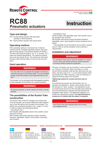
Actuators for heating,ventilation, air-conditioningELECTRONIC VALVESIZING AND SELECTIONV4.1Air Handling UnitCoilAABReheat Coil, Fan Coil, BaseboardCoil1 psi0.71.21.93.04.77.4101219293137394657Pressure drop5 psi1.72.74.26.711172227426469838710312710 psi2.33.86.09.515233238609298117123145180
Table of contents Introduction . . . . . . . . . . . . . . . . . . . . . . . . . . . . . . . . . . . . . . . . . . . . . . . . . . . . . . . . . . . . . . . . . . . . . . . . . .3I.Two-position control of hot and cold water . . . . . . . . . . . . . . . . . . . . . . . . . . . . . . . . . . . . . . . . . . . . . .3II.Two-way valve modulating control of coil water flow . . . . . . . . . . . . . . . . . . . . . . . . . . . . . . . . . . . . . . .8III.Two-way valve modulating control of system pump pressure . . . . . . . . . . . . . . . . . . . . . . . . . . . . . . . . .9IV.Three-way valve modulating flow control . . . . . . . . . . . . . . . . . . . . . . . . . . . . . . . . . . . . . . . . . . . . . . .10V.Three-way valve modulating control of temperature with constant flow . . . . . . . . . . . . . . . . . . . . . . . .10VI.Other considerations . . . . . . . . . . . . . . . . . . . . . . . . . . . . . . . . . . . . . . . . . . . . . . . . . . . . . . . . . . . . .11VII.Steam systems and 2-position control . . . . . . . . . . . . . . . . . . . . . . . . . . . . . . . . . . . . . . . . . . . . . . . .13VIII. Modulating control of low and high pressure steam . . . . . . . . . . . . . . . . . . . . . . . . . . . . . . . . . . . . . . .13Figures1aTwo-way valves in 2-position applications . . . . . . . . . . . . . . . . . . . . . . . . . . . . . . . . . . . . . . . . . . . . . . .31bThree-way valves in 2-position applications . . . . . . . . . . . . . . . . . . . . . . . . . . . . . . . . . . . . . . . . . . . . .32aTwo-way valves in modulating applications . . . . . . . . . . . . . . . . . . . . . . . . . . . . . . . . . . . . . . . . . . . . . .82bPressure loss for modulating control . . . . . . . . . . . . . . . . . . . . . . . . . . . . . . . . . . . . . . . . . . . . . . . . . . .92cAuthority . . . . . . . . . . . . . . . . . . . . . . . . . . . . . . . . . . . . . . . . . . . . . . . . . . . . . . . . . . . . . . . . . . . . . .103Two-way modulating valves controlling pressure . . . . . . . . . . . . . . . . . . . . . . . . . . . . . . . . . . . . . . . . .104Three-way valves in high pressure drop applications — flow control . . . . . . . . . . . . . . . . . . . . . . . . . .105aThree-way valve low pressure drop — coil runaround pump . . . . . . . . . . . . . . . . . . . . . . . . . . . . . . . .105bControl of Condenser Temperature . . . . . . . . . . . . . . . . . . . . . . . . . . . . . . . . . . . . . . . . . . . . . . . . . . .115cPerimeter Loop Reset . . . . . . . . . . . . . . . . . . . . . . . . . . . . . . . . . . . . . . . . . . . . . . . . . . . . . . . . . . . .116Boiler, Pump, and Piping System — Head Pressure Calculations . . . . . . . . . . . . . . . . . . . . . . . . . . . .127Steam valve applications . . . . . . . . . . . . . . . . . . . . . . . . . . . . . . . . . . . . . . . . . . . . . . . . . . . . . . . . . .132DOC.V4.1-03.99-7.5M - Printed in USA - IG - Subject to technical changesTablesACharacterized Ball Valve Cv . . . . . . . . . . . . . . . . . . . . . . . . . . . . . . . . . . . . . . . . . . . . . . . . . . . . . . . . .5BGlobe Valve Cv . . . . . . . . . . . . . . . . . . . . . . . . . . . . . . . . . . . . . . . . . . . . . . . . . . . . . . . . . . . . . . . . . . .6CButterfly Valve Cv . . . . . . . . . . . . . . . . . . . . . . . . . . . . . . . . . . . . . . . . . . . . . . . . . . . . . . . . . . . . . . . . .8DGlycol specific gravity, g . . . . . . . . . . . . . . . . . . . . . . . . . . . . . . . . . . . . . . . . . . . . . . . . . . . . . . . . . . .11EFL for Valves . . . . . . . . . . . . . . . . . . . . . . . . . . . . . . . . . . . . . . . . . . . . . . . . . . . . . . . . . . . . . . . . . . . .11FVapor Pressures — Cavitation . . . . . . . . . . . . . . . . . . . . . . . . . . . . . . . . . . . . . . . . . . . . . . . . . . . . . .11GSpecific Volume — Steam Sizing . . . . . . . . . . . . . . . . . . . . . . . . . . . . . . . . . . . . . . . . . . . . . . . . . . . .13
Introduction / Two-position control of hot and cold waterIntroductionThe common applications in HVAC valve control, each ofwhich uses slightly different selection and sizing methods, aredefined in the section headings in the table of contents.SupplyCoilV1ReturnRadiator, Convection, Fan CoilMay be modulating also.In addition to sizing, it is necessary to check specifications toensure correct selection. Special conditions are possiblewhich may make selection more demanding than the commonapplications.Glycol or other additives may make the specific gravity necessary to include in calculations. NEMA 3 or higher applicationswill require a enclosure. A combination of medium or ambienttemperatures may make a special valve or protection of theactuator by thermal isolation necessary. Space constraintsmay dictate choice of valve type. Other special conditionsmay exist.DOC.V4.1-03.99-7.5M - Printed in USA - IG - Subject to technical changesThe information necessary to properly size a valve is thesame in all cases. If full information is not available, there willbe cases where the valve will be incorrectly sized or the wrongvalve will be selected. The pressure drop through coil and piping at design is usually unknown. Without this information correct sizing and selection cannot be assured. An adequateestimate is usually possible. See Belimo’s ValveApplication Guide Doc V4.2 for a detailed discussion ofbasics of valves, coil characteristics, valve authority, actuatorconsiderations, loop tuning, and heat transfer calculations.Sizing information: Pipe size Flow rate in GPM or # of steam Density of medium (water 1) Pressure drop through coil and piping at design Desired pressure drop through valve in full openpositionSelection information: 2-way or 3-way Allowable leakage Temperature of medium and ambient Environment (Nema 4 required, ambienttemperature, etc.) Space constraints Actuator selection requires control signal definitionand any special needsNote that diverting tee system shouldtake minimal pressure loss thru valves.CoilDiverting TeeLarge Zone Isolation ValvesSee Belimo specificationsfor temperature limitsBoiler Water FeedTankSupplyReturnBoilerFig. 1a - Two-way valves in 2-position applicationsSYSTEM CHANGEOVERABAABoilerABMixing Valveused as 2positionB DivertingBChillerZONE CHANGEOVER 4 PIPE SYSTEMABCoilADiverting B 3-WaySequenced2-PositionControl ValvesThese are modulatingI. Two-position control of hot and cold waterTwo psi is typically the maximum pressure loss allowed. Tento 20% of the supply to return differential pressure is alsoused as a rule of thumb. Figure 1a shows common applications for 2-way valves in 2-position control. Figure 1bshows common 3-way valve applications in 2-positionapplications.Return1 pipe systemHWS CWSHWRCWRFig. 1b - Three-way valves in 2-position applications3
Two-position control of hot and cold waterGlobe, ball, zone, and Belimo Characterized Control BallValves will normally be full line size in 2-position applications.There is no reason to use characterized valves for these applications unless planning to go to modulation at a later date.The ball or butterfly valve is less expensive and has a highercapacity – lower pressure loss — for large valves. In somecases, particularly with butterfly valves, the valve can bereduced a pipe size to save money and still produce a lowenough pressure loss.Standard full port and reduced port ball valves and butterflyvalves used in 2-position applications can be full line size.They may be reduced if the calculations are performed andshow a low enough pressure drop.Cv is the capacity of water in GPM which flows through avalve with a 1 psi pressure loss.The formula for calculating the Cv needed isFp & CvThe Cv of a high capacity valve diminishes significantly as thepipe size is increased. This is calculated using the pipinggeometry factor or Fp. Cvc is corrected Cv. It is found usingCvc Cv x Fp.Fp can be estimated for average concentric reducers using aformula shown in Belimo’s Control Valve Applications Guide.High capacity valves ( standard ball valves and butterflyvalves) have a low Fp; the capacity is greatly reduced. Lowcapacity valves like the globe and characterized ball valvehave Fp near 1; there is little reduction in capacity from usingreducers.In Table A the full port, high capacity valves are marked.When using them in pipes larger than the valve size the Cvctable at the bottom of the page should be used to find the corrected Cv.Cv GPM / P/g(g 1 for water and therefore Cv GPM / P)It is typical to select a 2-position valve with a Cv GPMrequired. Examination of the sizing tables shows that linesize valves are usually selected.Example 1:A zone isolation valve must pass 10 GPM. The line size is1”. What size valves are acceptable for a ball valve and aglobe valve?Assume that the pressure drop should be 1 psi at the most.Select a line size valve. From Table 1 a 1” ball valve in a 1”line has a Cv of 23.Using Cv GPM / P and P 1 and substituting,Cv 10 / 1.Cv 10. This is the minimum Cv required.Any valve with Cv equal to or greater than 10 will work.Now find the globe which fits.From Table B there are 1” globe valves with Cv’s of 10 and14. The pressure drop is less for the Cv 14 and normallyit is selected.Note that the rule of thumb can be that the required Cv isequal to or greater than the GPM required or line size.There are other reduced pipe size valves that could also beused.4DOC.V4.1-03.99-7.5M - Printed in USA - IG - Subject to technical changesTable A gives the Cv’s of the Belimo characterized ball valveline. Note that there are full ported versions also available for2-position use. Table B has Belimo globe valve Cv values.
Two-position control of hot and cold waterTable A: Valve Flow Rate for Water Applications (Gallons Per Minute, GPM)DOC.V4.1-03.99-7.5M - Printed in USA - IG - Subject to technical 247.410193010192537192937294657GPM Cv 2"1-1/2"2"2"2" 10B311B312B313Pressure drop across the valve1 026122026632026507926506698507798771221518 327623326095326079117609211792145180* Models with no characterizing disc.The influence of the pipe geometry due to reduced flow is negligible for all valves with characterizing discs.Table B: Cv for Valves Without Characterizing Discs.Valve sizeModel #InchesDN 2301-1/4"32B2321-1/4"32B2401-1/2"40B2502"50-Full port valve size smaller than line(without characterizing disc)1"6.319.030.0-1-1/4"16.127.319.037.0-Line ” should be as short as possible. Length will influencethe resulting Cv value of a full ported ball valve.5
Two-position control of hot and cold waterValve Flow Rate for Water Applications 0Pressure drop across the valve1 psi0.41.32.24.45.57.51014202840Valve Flow Rate for Low Pressure Steam 69987psi1.13.45.811.614.519.8263753741068 3.917.423.73244638912610 psi15 psi2-positionModulating 2-positionModulating10% of P180% of P110% of P180% of P1 P 1 psi P 8 psi P 1.5 psi P 12 9971546122458413877801749# / hr. SteamInlet - psig20 psi25 psi2-positionModulating 2-position Modulating10% of P1.42 of P110% of P1.42 of P1 P 2 psi P 14 psi P 2.5 psi P 16 1766791439810164697020561157235130 psi35 psi2-positionModulating 2-positionModulating10% of P1.42 of P110% of P1.42 of P1 P 3 psi P 18 psi P 3.5 psi P 20 14729401853106820601342264815262944The influence of the pipe reduction factor on the flow for the Belimo electronic globe valves is negligible.69psi1.23.96.613.216.522.530426084120# / hr. SteamInlet - psig2 psi5 psi2-positionModulating 2-position Modulating10% of P180% of P1 10% of P180% of P1 P .2 psi P 1.6 psi P .5 psi P 4 666218590371951Valve Flow Rate for Medium Pressure Steam .V4.1-03.99-7.5M - Printed in USA - IG - Subject to technical changesCv
Two-position control of hot and cold waterValve Flow Rate for Water Applications (GPM) Two-Way Globe ValveCvValvePressure drop across the 00G6125G61501 04166448437psi1722384506969108 3883210888 0188510758 7617784Valve Flow Rate for Water Applications (GPM) Three-Way Mixing Globe ValveCvValvePressure drop across the 00G7125G71501 34656868337psi180241503741900Valve Flow Rate for Water Applications (GPM) Three-Way Diverting Globe ValveCvValvePressure drop across the valveDOC.V4.1-03.99-7.5M - Printed in USA - IG - Subject to technical DG7100DG7125DG7150D1 83774786077psi180225407516656The influence of the pipe reduction factor on the flow for the Belimo electronic globe valves is negligible.Valve Flow Rate for Low Pressure Steam obeValveG665G680G6100G6125G61502 psi5 psi2-positionModulating 2-position Modulating10% of P180% of P1 10% of P180% of P1 P .2 psi P 1.6 psi P .5 psi P 4 878244562531875507331988178Valve Flow Rate for High Pressure Steam obeValveG665G680G6100G6125G6150lbs. / hr. SteamInlet - psig10 psi15 psi2-positionModulating 2-positionModulating10% of P180% of P110% of P180% of P1 P 1 psi P 8 psi P 1.5 psi P 12 38419120513211499502411928671215040lbs. / hr. SteamInlet - psig20 psi25 psi2-positionModulating 2-position Modulating10% of P1.42 of P110% of P1.42 of P1 P 2 psi P 14 psi P 2.5 psi P 16 163811343276091536483461756899522009830 psi35 psi2-positionModulating 2-positionModulating10% of P1.42 of P110% of P1.42 of P1 P 3 psi P 18 psi P 3.5 psi P 20 4308825172971003319230115432262413123251527
Two-way valve modulating control of coil water flowTable C is a butterfly valve table with Cv shown for variousvalve and pipe sizes.Since the table shows that a 4” valve in a 4” pipe passes 660GPM with a 1 psi loss, it is selected for the application whichwill require only 600 GPM.For example, 600 GPM must flow through a 4” pipe and valvewith a pressure drop of no more than 1 psi.ValveSizePipeSizeCvc at degrees open60 70 90 Full Open — 90Flow in GPM at pressure drop of:1 psi2 psi3 psi4 psi5 psi6 581258177921796”10”5535871048104814821815Not rated for steam.Note: Values for Cv in pipes larger than valve in table above are calculated for average reducers.322625162096360728132343395130812567II. Two-way valve modulating control of coil water flowAir Handling UnitCoilAABReheat Coil, Fan Coil, BaseboardCoilFigure 2a - Two-Way Valves in Modulating Applications8Figure 2a shows the primary applications which use 2-wayvalves in modulating applications. These applications are themost common in commercial HVAC control. The valvesshould be equal percentage.The use of tables is an accurate and fast method for sizing.The Belimo characterized control ball valve is similar to theglobe in Cv. Unlike the standard ball valve it also has a trueequal percentage modulating response curve similar to theglobe. It will not normally require multiple reducers to adjustthe Cv for pipe variations. Tables A to C give Cv and Cvc forControl Ball, Globe, and Butterfly valves.In Figure 2b example pressure losses are shown for the pipeelements. The valve is 50% of the circuit’s loss. This gives ita 50% authority which produces an adequate response curve.In 2 way valve applications, the authority should be as high aspossible. Better than 50% as shown here would be 75% ifpossible. See Belimo’s Control Valve Application Guide for afull description.DOC.V4.1-03.99-7.5M - Printed in USA - IG - Subject to technical changesTable CButterfly Valves
Two-way valve controlling pressureTwo way valves should be sized for Cv based on thesupply to return differential, not the coil loss. Equalpercent valves are necessary. As much pressure lossas possible should be taken across the valve to achievethe deep equal percentage curve.Since differentials are typically unknown, the 5 psi ruleof thumb has evolved. Size the valve for 4 to 9 psi dropat design flow.3. A similar method is to size the valve to be no lesspressure loss than the coil. Again it is rare that thepressure drop is known. The consultant has the data butit is not put on drawings. Low bid adherence may lead toa different coil than specified being used.These rule of thumb methods are not as accurate as fullhydraulic analysis as shown in Fig. 2c.Coil 4 psi at designCooling coils are more sensitive to undersizing thanheating coils. Size appropriately.CoilBVV1Figure 2c shows a system with 2 valves. If the valves weresized for 5 psi drop, then V1 would be OK. It has pressurelosses similar to those given in 2b. However, valve V2 wouldbe grossly oversized at a 5 psi drop. The balancing valvewould be set to take a high loss. This would give the valve alow authority and it would resemble a quick opening valve.Control would hunt and accuracy would be hard to maintain.As the valve closed it would take higher and higher pressure losses. This would lead to increased flow wellbeyond that which the inherent curve indicates. It has alow authority, over the linear curve.Typically the control engineer does not have full pressure andloss data. In this case the valve is sized using rules of thumbwhich ignore the fuller hydraulic analysis recommended.DOC.V4.1-03.99-7.5M - Printed in USA - IG - Subject to technical changesWhen the coil drop is unknown, it is assumed to be about 4psi. Actual drops range from 1 psi to 10 psi according to coilmanufacturer tables.Supply to return differential is low since far from pumpAssume S to R 10 psiHeight 100'V1 should be about 5 psi drop at rated CvV2 should be about 20 psi drop at rated CvCoil 4 psi at designCoilBVV2Supply to return differential is high since close to pump.Assume S to R 25 psiHeight 10'ExpansionTankReturnBoilerPumpPump Head 45' at 500 GPMBV Balancing ValveAir Handling UnitFig. 2c - AuthorityCoil1/2 psi4 psi5 psi1/2 psiFigure 2b - Pressure loss for modulating controlThree methods are commonly used to size valves in modulating applications:1. One quick method is to size the valve for 3 to 5 psi ornominally 4 psi pressure drop when full open.Cv GPM / 2 or GPM 2 Cv ( since 4 2)This formula is very easy to use and is as accurate as anyother method. Size the valve for a Cv 1/2 the GPM itmust pass in modulating applications. When the valves fallbetween Cv required, size for the smaller valve in heatingapplications. Note that a 9 psi drop gives GPM 3 Cvwhich would be an upper limit for heating pressure drops.When the valves fall between Cv required for coolingvalves, select for the larger.2. Another method is to size the valve to be from 1/2 to 3/4the supply to return drop. This will give good control.However the pressure drop is often unknown.Example 2.Given a heating coil with a 60 GPM modulating requirementand pipe size of 2” with no other information.Assume P 4 psi and required Cv GPM / 2. Required Cv 60 / 2 30.Go to Table A and select valve: the Cv 31 of the 2” characterized valve is correct, as is Cv 29 of the 1-1/2” valve.Alternately the valve may be selected by going to the 4 psipressure drop column and reading down comparing pipesizes to the Cv. One arrives at the same valve.Butterfly valves must be frequently limited in amount of rotation. It is common practice to consider the modulating rangeof a butterfly to be between 15 and 70 . A smaller valve isused for fine control below useful range of the butterfly.III. Two-way valve modulating control of system pressureFigure 3 is another example of a 2-way valve application, butrather than controlling flow to gain temperature control, theflow is controlled to keep the system pressures from rising.This application can be designed using a number of differentmethods. One is to decide on a limit in pressure differentialbetween the supply and return and use this as the setpoint ofa controller. The pump curve must be examined by the designengineer to find what setpoint to use. When it reaches the9
Three-way valve modulating control of flow and temperaturesetpoint, the bypass valve starts to open. It passes waterthrough to keep the pump at a pressure limit. At maximum,the valve will have the same supply to return pressure difference, but the flow will have increased to a maximum.Figures 4 shows the common 3-way valve application whichcontrols flow.Standard AirHandling UnitCoilMixingASystem BypassBVBABBVGlobeBallBoilerHWSThe valves here arebypassing flow backto the pump in orderto keep the systempressure at a designvalue.Fig. 3 - Two way modulating valves controlling pressureExample 3.System bypass line is 2”. Given that the differential will be 9psi and the valve must pass 100 GPM.Cv GPM / PCv 100 / 9 33From Table A, a 2” valve with a Cv of 46 will be correct.Note that this application uses different pressures and capacities than temperature control applications. A pump bypass issimilar.Example 4.System bypass line is 4”. Given that the differential will be 16psi and the valve must pass 400 GPM. A butterfly valve isspecified.Cv GPM / PCv 400 / 16 400 / 4 100Look at Table C for a butterfly valve. The 2.5” in the 4” linehas a Cv of 98 when 70 open and Cv of 93 when 60 open.Thus is will be open about 75 at the maximum — a goodamount for modulation.HWRFig. 4 - Three way valves inhigh pressure drop applicationsThe formula used for sizing isGPM Cv P, the same as for 2-way valves.Since P about 4, P 2 and the required Cv GPM/ 2.This valve is normally sized to be the same pressure loss asthe coil. These valves should have equal percentage characteristics.Sizing methods are similar to those for two way valves.The A port, control, should be equal percent. The B port,bypass, is best linear to maintain constant flow in the primary system, but can be equal percentage. The valveshould take a high percentage of the supply to returnpressure difference. No less than the coil or 4 to 9 psi isused as the rule of thumb when the actual pressures areunknown.V. Three-way valve modulating control of temperaturewith constant flowCoil pumpFigure 5a shows the common 3-way valve application with acoil pump. This application controls temperature, not flow, asthe other control methods do. Sizing techniques are different in this application.CoilSee Belimo’s Valve Applications Guide Doc V4.2 for discussion.Runaround PumpABBIV. Three-way valve modulating control of flowWhen controlling flow the valve is sized to take a high pressure drop. Normally the higher of 3 to 5 psi or the coil pressure drop is the goal. Thus 4 psi drop is the nominal goal.AHWSHWRFig. 5a - Three-way valve inconstant flow application10DOC.V4.1-03.99-7.5M - Printed in USA - IG - Subject to technical changesPumpBypass
Other ConsiderationsIn the previous application the valve is controlling temperature,not flow. The flow is constant but the temperature is varied bymixing return with supply water.It is not sized for a high pressure drop. It can be sizedline size or about the same pressure drop as the coil atthe maximum. Equal percent recommended.VI. Other considerationsGlycol does not have a strong effect on the valve sizingbecause g, the specific gravity, is relatively small. Rarely will avalve need to be increased in size due to change in specificgravity. However, the heat capacity of the mixture is lowerthan water and does affect the GPM requirement. The designengineer will include this in his coil and GPM requirementsand specify the mixture required.COOLING TOWERPressure drop thruvalve should beNequal to that from NozzlesA to N. PressureCoolingat N must beTowersufficient fornozzles, if used.A3-wayDivertingBABCondenserFig. 5b - Three-way valves in low pressuredrop application — Control of TemperatureCooling towerIn Figure 5b, a 3-way diverting valve is installed for a coolingtower bypass.DOC.V4.1-03.99-7.5M - Printed in USA - IG - Subject to technical changesThis valve may not be sized without a known requiredpressure drop. Failure to verify the allowable drop willlead to problems.Table DEthyleneGlycol% byweight10203040SpecificGravity% byvolume9182737PropyleneGlycol% by% byweightvolume7101720263037404650FreezingPoint F FreezingPoint F tionCavitation does not occur with steam valves. It can be predicted for water valves by solving this equation:Maximum allowable P FL2 (P1 - VP)Sizing and selection are performed in the same way as othermodulating valves, but the pressure drop is based on therequirement of the system. There must be enough pressureon the valve outlet port, A, to the spray nozzles to push thewater through. The pressure at the B port is typically too high,and overflow would occur without a balancing valve.Perimeter Loop ResetSee Figure 5c. This valve is normally line size. It controls themixture of water to set the perimeter temperature. It does notneed to take a high pressure loss. A balancing valve may beinstalled in the bypass port to return pipe to equal the boilerpressure drop. The valve is normally line size; linear characteristic is recommended.Valve controls temperatureand has a low pressuredrop. Size for 10% ofloop pressure loss atmaximum or line size.ABABBoilerSupply3-WayMixingReturnFL is the liquid pressure recovery factor.P1 is the inlet pressure psia.VP is the vapor pressure in psia at inlet temperature.Table EFL11.65.5.5Type ValveGlobesControl BallButterfliesButterfliesStandard BallAmount OpenAll positionsAll positions70 open90 open90 openTable FVP Vapor pressure of water 4.7See Belimo’s Valves Control Applications Guide Doc V4.2for more detail on this subject.Fig. 5c — Perimeter Loop Reset11
Other considerationsDetermining the required valve pressure ratingsValves have a number of pressure conditions which must beconsidered. They have 2 ratings — body and stem static rating and disc and seat close-off rating. Static rating is theamount of total p
SIZING AND SELECTION Coil Air Handling Unit Coil Reheat Coil, Fan Coil, Baseboard A AB Pressure drop 1 psi 5 psi 10 psi 0.7 1.7 2.3 1.2 2.7 3.8 1.9 4.2 6.0 3.0 6.7 9.5 4.7 11 15 7.4 17 23 10 22 32 12 27 38 19 42 60 29 64 92 31 69 98 37 83 117 39 87 123 46 103 145 57 127 180