Transcription
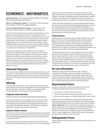
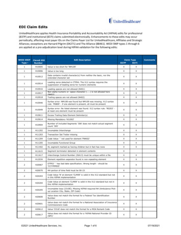
71762-00001 AINSTRUCTION MANUALECON-ZIP-SDTF; ZIP PACKContains:ECON-ZIP-SDTF; ZIP PACKSingle Dry Bulb with DCV Capability and TF SpringReturn ActuatorApplicationThis kit offers all the components to retrofit an economizer on a directexpansion RTUs up to 7.5 tons while utilizing single dry bulb changeoverstrategy. In this, the ZIP Economizer will compare outside air dry bulbtemperature to a fixed setpoint, or high limit changeover temperature,(based on your climate zone) to control the economizer cycle. Onetemperature sensor will be place on the outside damper, and the other inthe supply duct. That high limit changeover temperature is adjustable.ECON-ZIP-BASE(2) ECON-ZIP-10KECON-ZIP-EMTFB24-SRand Retrofit KitWhen the included energy module is used (ECON-ZIP-EM), the followingoptions become available: demand control ventilation, pre occupancy purge,power exhaust, remote damper position override, fan speed switch.Wiring DiagramsNotes:57ACT 11ACT 2ACT 3ACT 5THERMOSTATRTU TERMINALRRACT1ACT2ACT3RRACT5- Common2 Hot3Y Input, 2 to 10V5U Output, 2 to 10V51CGOCCOCC56O/B03/15 - Subject to change. Belimo Aircontrols (USA), Inc.CSAT GW1SAT-ECON-ZIP-10KSupply Air TempY1RAT OAT Y2RAT-OAT-CC1RAH OAH OAT Y1Y1Y2Y2RTU Stage 1Mechanical CoolingCircuitry53RTU Stage 2Mechanical CoolingCircuitryCC2CC2RAH-ECON-ZIP-10KOutside Air TempOAH-Purge ContactThermostat24 VACAUX1 AUX1 -Y Input, 2 to 10 VDC 32 to 10 VDC 4SGA24SGF2455Energy ModuleAUX1 CO2 AUX1 -CO2 -CO2 CO2 -54- Common2 3 Y Input, 0 to 10 VDC4- 0 to 10 VDCCO2 Sensor150AUX2 53Existing refrigeration safety devices may exist,consult RTU wiring diagram54Not supplied by Belimo.55Sold separately by Belimo56If RTU is not a Heat Pump using a conventionalthermostat and it is desired to record heatingoperation hours, connect W1 to ECON-ZIP-BASE.57Actuators can be mounted in parallel with the ACT3output from the ZIP Economizer. The ACT5 feedbackinput should be wired to the Outside Air damperactuator feedback wire.ECON-ZIP-BASE1252W1 must be wired for Heat Pump operation ifconventional thermostat is used in conjunctionwith Defrost Board. If Thermostat and RTU use O/Bcontrol reversing valve position, O/B must be wiredto W1 on ECON-ZIP-BASE.CC150 When the thermostat is not equipped withoccupancy control, "Fan On" output "G" shall bewired to the ECON-ZIP-BASE.OAT -Single Dry BulbCommon -51SAT -W1W152CPower source should be the same as ECON-ZIP-BASE.-SRSAT C50AUX2 IFAUX2 -EFECON-ZIP-EMIndoor Fan LowSpeed Relay / VFD EnableExhaust FanCircuit52
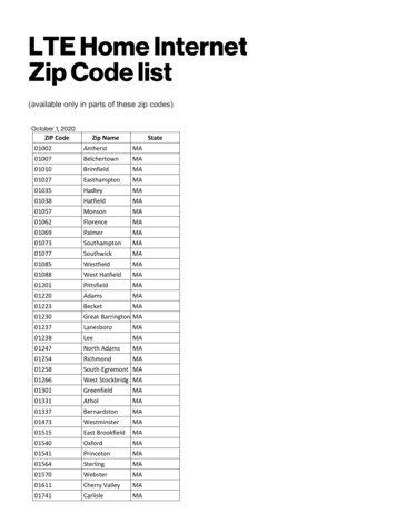
ZIP EconomizerSetup and ConfigurationQuick SetupWARNING Live Electrical Components!During installation, testing, servicing and troubleshooting of this product, it may benecessary to work with live electrical components. Have a qualified licensed electrician or otherindividual who has been properly trained in handling live electrical components perform thesetasks. Failure to follow all electrical safety precautions when exposed to live electricalcomponents could result in death or serious injury.InstallationSettings1. Shut off power to RTU before beginning installation.2. Note orientation, opening rotation, and spring return rotation of damperassembly. Mount Actuator to Outside Air and Return Damper assembly.To ensure tight outside air shutoff; while tightening actuator clamp pushdamper closed.3. Terminate required Inputs and Outputs(I/O): For the ZIP Economizer tofunction correctly, the following I/O, at a minimum, are required to beterminated, wired, and functioning (R, C, Y1, Y2, G, CC1, OAT, SAT, ACT1,ACT2, ACT3, ACT5). See wiring diagrams.4. Sensor configuation: The ZIP Economizer automatically detects sensorsattached and automatically configures for single dry bulb, single enthalpy,differential dry bulb and differential enthalpy.“Settings” is the menu displayed when the ZIP Economizer is first powered.Press “OK” to parameterize required settings. Reference above Keypad Keydefinition instructions and navigate as needed.Moves up through themenu on the same level.Will increase values byone increment at a time.When setting valuesholding key down willfast scrollescEnter sub menu level.Start editing a setting.Store an enteredvalue.2Moves down through themenu on the same level.Will decrease values byone increment at a time.When setting valuesholding key down will fastscroll.iEscape sub menu toShow additionalnext higher level.information on theCancel current actions. current menu Itemwhen “i” appears inlower right of display.1. “Monitor Live Conditions” is used to display settings and live values.2. “Settings” is used to parameterize the ZIP Economizer. (Note: Devices 1 isfor CC1, CC2, EF, IF; Devices 2 is for OAH, RAH)3. “Present Devices” is used to verify that the ZIP Economizer's Auto Detectedconnections are terminated properly. If connected device is not shown,verify wiring. If wiring has continuity and device is verified operationalre-enter “Settings” and enable missing device by changing from “Auto” to“Available” or “Installed”.4. “Alarms” is used to view current and historical alarms and deleteinadvertently caused alarms.5. “Service and Commissioning” submenu is used to operate the RTU in“Manual Mode” or to perform “Acceptance Test”. “Settings” must to becompleted to access.6. “Status” is a display of the current operating mode. It can be accessedby pressing ”esc”. The action of pressing any key will drop the user downfrom Status to the next level, so repeatedly pressing “esc” will toggle thedisplay between Status and Monitor Live Conditions. (Note: If status“Setup incomplete” is displayed the RTU cooling operation will bedisabled and additional parameters must be set to achieve “Setupcomplete”.)03/15 - Subject to change. Belimo Aircontrols (USA), Inc.MMI KeypadFunctions
ZIP EconomizerSetup and ConfigurationQuick SetupRequired "Settings" Parameters for All ConfigurationsNote: you may enter parameters in any order - eg: Vent min Pos beforeZIP Code - If the RTU is a heat pump or uses a 2 speed indoor fan, theseparamaters should be enabled first, otherwise the logic may go to SetupComplete prematurely.1. ZIP Code US or Canada (sets the free cooling changeover high limit andtemperature units F/C)a. When the Zip Code submenu is displayed enter “OK” to begin “US” ZipCode parameterization. If “Canada” Postal Code is desired press the up/down arrow to access.i. Press OK to access digit 1 (flashing) then use the up/down arrowto parameterize; enter OK when complete. Repeat until all digitsare complete. If a mistake is made press “esc” and repeat frombeginningWhen all Zip Code or Postal Code digits are entered press“esc” to move up a level then press the up/down arrow to accessnext settings parameter.2. Vent Min Pos (Outdoor Air Damper Ventilation Minimum Position)a. When the “Vent Min Pos” submenu is displayed press “OK” toparameterize (flashing).03/15 - Subject to change. Belimo Aircontrols (USA), Inc.ii.b. Use the up/down arrow to parameterize, press “OK” when complete.The actuator will immediately drive the damper to the minimum position.3. Additional Parameters may require setting. The ZIP Economizer will autodetect added Devices such as a CO2 sensor etc. When the ZIP Economizerdetects a new device, it will prompt the user in the Status level; navigate toSettings and parameterize blank fields. If the devices are connected uponfirst start up their settings will require parameterization then.4. When all parameters have been set, the ZIP Economizer will show “SetupComplete” if there are still parameters to set, there will be no action. Youcan verify by pushing esc until status level is reached and it will display“Setup Incomplete”. If this is the case, re-enter settings menu and use updown arrows to find the parameter with blank fields and parameterize asdescribed above.Once scaling is complete, a message will appear saying “Damper scalingsuccessful”. The ZIP will then show “maximum at 80 100%” Thatmessage will show maximum rotation of the damper. This process ensuresthe damper is always operating and displayed from 0-100%.2. Once the message has appeared, the actuator immediately closes thedamper and a countdown begins, until the unit starts to operate inAutomatic Mode (be aware, when countdown complete, the RTUwill respond to thermostat calls which may enable mechanicalcooling).Service and Commissioning (Acceptance Test & Manual Mode)The ZIP Economizer has built in commissioning processes found inAcceptance Test.1. Economizer Test. Use “Economizer Test” to verify RTU IntegratedEconomizer operation. Navigate to the “Service and Commissioning” menu,press “OK”; press the down arrow to access “Acceptance Test”. PressOK again when “Economizer Test” appears. Press “OK” again to confirmrunning test. Follow prompts during test. This test will open damperto 100%, enable power exhaust fan (if connected), enable 1st stage ofMechanical Cooling, reverse this process and then drive to Vent MinPosition. When used with a Belimo actuator, the actuator will speed up toreduce test time.2. Manual Mode is used to override outputs after entering a “Timeout”duration.3. Damper Scaling. The test will re-scale the control signal range tomaximum resolution (0-100%) over the calibrated (reduced) angle. Whenusing a Belimo actuator, the actuator will speed up to reduce test time.Note: Failure to identify obstructions or improper setup of damper assemblymay result in an improper scaling and operation of the damper.)Note: Additional testing can be found on page 36 of this document.Setup Complete - Initializing Automatic Mode1. When all entries have been completed, the ZIP Economizer will switch toStatus display and show “Setup Complete”, and will immediately show a“Damper scaling starts in 10secs” and will countdown to 0 (be aware,at 0 the damper will start to move at high speed) . A message willscroll saying “Damper scaling for better operation if obstruction is presentrescale damper in commissioning menu”. (For detailed instructions onthis – please see the section “Service and Commissioning” below. This willopen damper to 100% (re-scale control signal if needed). (Note: failure toidentify obstructions or improper setup of damper assembly may result inan improper scaling and operation of the damper.)3
ZIP EconomizerMenu Structure TablesSettingsParameterUSDefault00000Range5 Digit NumSetting of either US or Canada code required for Economizer Operation.Setting the ZIP code automatically configures the economizer high limit changeover temperature to comply with local energy code. If the user desires a differenthigh limit value, this can be modified in the “settings” menu under “high limitmodification”.6 Digit Alpha/NumSetting of either US or Canada code required for Economizer Operation.Setting the ZIP code automatically configures the economizer high limit changeover temperature to comply with local energy code. If the user desires a differenthigh limit value, this can be modified in the “settings” menu under “high limitmodification”.Zip Code1Canada000000OffHeat PumpOpHeat Pump OpOffHP (O) pow CoolHP (B) pow HeatHP (W1) pow HeatCompressorQty8Devices 1CC1, CC2, IF,EF,(asconnected)Number ofCompressorsAuto2Fan 2 Speed4Auto2Compressor Qty3Auto2Exh Fan Install4OAH5Auto2Auto2Devices 2OAH, RAH,(asconnected)RAH54Auto2NotesNo compressor detectedCompressor 1 detectedCompressor 2 but noCompressor 1 detectedCompressors 1 and 2detectedCompressors 1 and 2selectedCompressor 1 selectedAuto, Available, NotAvailableAuto, 1, 2Auto, Installed, NotInstalledAuto, Installed, NotInstalledAuto, Installed, NotInstalledIf the RTU that the economizer is installed in, is a heat pump, then this value shall beset to one of the following:(O) Reversing valve powered for cooling.(B) Reversing valve powered for heating.(W1) Standard thermostat, reversing valve controlled by internal RTU defrost board.Message appears only during initial setup. If No Compressor is detected, verify wiring,check continuity, if all is correct, push OK to set quantity.If only 1 compressor is detected, and there are 2 installed verify wiring, checkcontinuity, if all is correct, push OK to set quantity.Allows for 2 speed indoor fan control circuit (IF) to be automatically detected whenwired. If circuit is not automatically detected, the functionality can be manuallyenabled by choosing “available.” If there is a desire to disable functionality for anyreason, the operator can choose “not available” and the operation of the economizerwill function as if the device is not installed or configured.Allows for up to 2 compressor circuits (CC1, CC2) to be automatically detected whenwired. If circuit is not automatically detected, the functionality can be manuallyenabled by setting compressor Qty to 1 or 2.Allows for exhaust fan control circuit (EF) to be automatically detected when wired.If circuit is not automatically detected, the functionality can be manually enabledby choosing “available.” If there is a desire to disable functionality for any reason,the operator can choose “not available” and the operation of the economizer willfunction as if the device is not installed or configured.Allows for the Outside Air Humidity Sensor to be automatically detected when wiredfor enthalpy change over strategy. If the sensor is not automatically detected, thehumidity sensor can be manually enabled by choosing “installed.” If there is a desireto disable functionality for any reason, the operator can choose “not installed”,and the operation of the economizer will function as if the device is not installed orconfigured.Allows for the Return Air Humidity Sensor to be automatically detected when wiredfor differential enthalpy change over strategy. If the sensor is not automaticallydetected, the humidity sensor can be manually enabled by choosing “installed.” Ifthere is a desire to disable functionality for any reason, the operator can choose “notinstalled,” and the operation of the economizer will function as if the device is notinstalled or configured.03/15 - Subject to change. Belimo Aircontrols (USA), Inc.Menu Item
ZIP EconomizerMenu Structure TablesMenu ItemVent Min Pos1DCV Min Pos4DCV PPM SetPnt42 Speed FanOp03/15 - Subject to change. Belimo Aircontrols (USA), Inc.Low Sp VentMin6ParameterVent Min PosDCV Min PosDCV PPM Set Pnt2 Speed FanOperationLow Sp Vent MinDefaultRangeNotes0-100%Setting the minimum position required for Economizer Operation.This is where the outdoor damper minimum position is set. This is the position thatthe damper will travel to during occupied periods (when terminal G on economizer ispowered). The amount of outdoor air is different per application. Please consult localventilation codes. This setting is typically related to a calculation that determinesamount of fresh air for building area and people (Vbz Ventilation Breathing Zoneper ASHRE 62.1). Actual airflow at a given position should be verified by fieldmeasurement.0% - Vent Min Pos %This is the Demand Control Ventilation minimum position. The DCV min pos is a valuealways less than the design ventilation position. This is the position that the damperwill travel to during occupied periods (when terminal G on economizer is powered)when the measure CO2 Value is below the DCV PPM Set Pnt. The amount of outdoorair is different per application. Please consult local ventilation codes. This settingis typically related to a calculation that determines amount of fresh air for buildingarea (Ra outdoor airflow rate required per unit area per ASHRE 62.1) to allowcontinue flushing of VOCs during occupied periods. Actual airflow at a given positionshould be verified by field measurement.ppm500 - 2000 ppmThis is the CO2 concentration that is desired to maintain in the space. When the CO2sensor measures a concentration below this value, the damper control point will bereset and the damper will modulate towards DCV Min Pos. When the measured CO2level increases above this value, the damper will start to modulate towards the VentMin Pos to lower the CO2 in the space.OffOnOffIf the unit is factory installed with 2 speed fan capability, then this setting must be setto On to provide proper ventilation.%"Vent Min Pos" % 100%When a 2 Speed strategy is used to save energy, an additional Vent Min Pos needsto be entered for low speed operation due to less available static pressure fromthe fan. This position will be greater than Vent Min Pos, however equal the samemeasured airflowrate value.When a 2 Speed strategy is used to save energy, an additional DCV Min Pos needsto be entered for low speed operation due to less available static pressure fromthe fan. This position will be greater than DCV Min Pos, however equal the samemeasured airflow rate value.%%Low Sp DCVMin6Low Sp DCV Min%"DCV Min Pos" % "Low Sp Vent Min" %Exh Fan OnPos4Exh Fan On Pos%0 - 100%This is where the desired enable point for exhaust fan operation is set. As theoutdoor damper increases or decrease past this position, the exhaust fan will beturned on or off.Low Exh FanPos6Low Exh Fan Pos%0 - 100%When a 2 Speed strategy is used to save energy, an additional Exh Fan On Pos needsto be entered for low speed operation due to less available static pressure fromthe fan. This position will be greater than Exh Fan On Pos, however equal the samemeasured space pressure.Temp UnitTemp Unit F F, CAllows the user to select Fahrenheit or Celsius temperature display. When the ZIPEconomizer is set up with a Canadian Postal Code, the units are default to C.Purge Enable4Purge DmpSet4Remote DmpCntrl4Purge ControlOffOn, OffThis is where Pre-Occupancy purge control is enabled. Pre-Occupancy purge is arequirement in some codes to ventilate the building just prior to normal occupancytimes. The function removes VOCs that have gathered in the building duringunoccupied period when the Outside air damper is normally closed. Purge Controlrequires using the expansion energy module and a thermostat or other time drivencontrol that will enable supply fan and provide 24V to Aux 1 during the desired purgeperiod. Setting of “Purge Dmp Set” is required for the function to work.Purge Dmp Set%0% - "Vent Min Pos" %This determines the position that the damper will open to during Pre-Occupancypurge. This position is usually based what will achieve the desired number of airchanges.Remote DmpCntrlOffOn, OffThis is where an optional outdoor air damper position override can be enabled. Inputinto AUX2 is 2-10 VDC (2V damper closed - 10V 100% open). This function overridesall other damper position settings Except: not in Automatic, G not energized FP.5
ZIP EconomizerMenu Structure TablesMenu ItemParameterHigh LimitDry BulbHigh LimitModificationHigh LimitFixed Enthalpy5High LimitDiff EnthalpySAT Y2 LimitSAT Y2 LimitDefaultRangeZIP CodeDependent60-80 F16-27 C28 BTU/lb47 kJ/kg25-28 BTU/lb40-52 kJ/kgZIP CodeDependent60-80 F16-27 C30 BTU/lb52 kJ/kg25-30 BTU/lb40-52 kJ/kgZIP CodeDependent60-80 F16-27 COnOn, OffNotesIf the High Limit Change Over Setpoint that was determined by the ZIP Code setupis deemed to be not desirable for the application, then it can be modified here.With Differential Enthalpy, temperature can also be changed; offsets cannot. Note:a modification may result in less energy savings and non compliance with localenergy code.SAT Y2 Limit is an energy saving function that prevents 2nd stage to get engagedwhen the Supply Air Temperature is at 56.5 F or below. When "On" there will be 4min delay from the time Y2 is on until the 2nd stage compressor will be enabledallowing 1st stage to try to satisfy SAT requirement. When “off”, 2nd stage is notlimited and compressor delay is 10 seconds. This function saves energy by havingone stage of cooling satisfy space cooling requirements.1. Required setting for Economizer operation. If the value is not set, outputs of the economizer such as compressors will not operate regardless of thermostat call.2. Attached Devices will be automatically detected and the related functionality will be enabled. When devices are detected, they will appear in the Present Devices menu and the Setup Settingsmenu will also automatically configure to display parameter to setup. For example, when an Exhaust Fan (EF) is detected, the "Exh Fan On Pos" will show in the menu and will require setup.3. At least 1 compressor is required (auto detected or chosen) for economizer to function.4. Requires the Energy Module connected and the accessory component powered, wired, and terminated to the Energy Module.5. Only visible when Humidity Sensor is present.6. Requires the Energy Module connected, 2 speed fan installed, and the accessory component or device powered, wired, and terminated to the Energy Module. 2 Speed Fan can be enabled insettings menu.7. Not visible when differential dry bulb or differential enthalpy change over strategies are used.03/15 - Subject to change. Belimo Aircontrols (USA), Inc.8. Only present at initial setup.6
1. ZIP Code US or Canada (sets the free cooling changeover high limit and temperature units F/C) a. When the Zip Code submenu is displayed enter "OK" to begin "US" Zip Code parameterization. If "Canada" Postal Code is desired press the up/ down arrow to access. i. Press OK to access digit 1 (fl ashing) then use the up/down arrow