Transcription
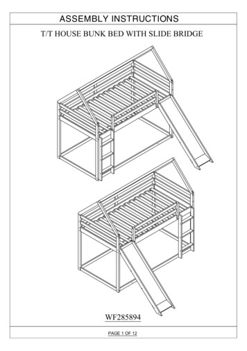
ASSEMBLY INSTRUCTIONST/T HOUSE BUNK BED WITH SLIDE BRIDGEWF285894PAGE 1 OF 12
ASSEMBLY INSTRUCTIONS!SAFETY WARNINGS!1. This bed is designed for use only mattress (es) meeting the following specifications on the upper bunk, andlower bunk:Upper bunk (bunk bed and tribed included)Bed TypeLengthWidthThickness11Twin Standard74" - 75"37 2" - 38 2"6" max2. Replacement parts, including additional guardrails, maybe obtained from any of our (GIGACLOUDTECHNOLOGY (USA) INC. 18961 ARENTH AVENUE CITY OF INDUSTRY, CA, 91748) dealers3. Follow the information on the warnings appearing on the upper bunk bed end structure and on the carton.Do not remove warning label from bed.4. Always use the recommended size mattresses or mattress supports, or both, to help prevent the likelihood ofentrapment or falls.5. Surface of mattress must be at least 5" (127mm) below the upper edge of guardrails.6. Do not allow children under 6 years of age to use the upper bunk.7. Periodically check and ensure that the guardrail, ladder, and other components are in their proper position,free from damage, and that all connectors are tight.8. Do not allow horseplay on or under the bed and prohibit jumping on the bed.9. Always use the ladder for entering and leaving the upper bunk.10. Do not use substitute part. Contact the manufacture or dealer for replacement part.11. Use of a night light may provide added safety precaution for a child using the upper bunk.12. Always use guardrails on both long sides of the upper bunk. If the bunk bed will be placed next to the wall,the guardrail that runs the full length of the bed should be placed against the wall to prevent entrapmentbetween the bed and wall.13. The use of water or sleep flotation mattresses is prohibited.14. STRANGULATION HAZARD - Never attach or hang items to any part of the bunk bed that are notdesigned for use with the bed; for example, but not limited to, hook, belts and jump ropes.15. Keep these instruction for future reference.16. Prohibit more than one person on upper bunk17. We recommend assembling your bunk bed on the shipping carton to protect your floor or carpet.18. Be certain all staples are out of the box before beginning assembly on the shipping carton.PAGE 2 OF 12
ASSEMBLY INSTRUCTIONS1. At the beginning :Tighten all hardware.Check metal parts for rust. If found, sand and repaint using a non-lead-based paint meeting therequirements of 16 CFR 1303.Check all wood members for deterioration and splinters. Sand down splinters and replacedeteriorating wood members.Rake and check depth of loose fill protective surfacing materials to prevent compaction and tomaintain appropriate depth. Replace as necessary.2. Twice a monthTighten all hardware.Rake and check depth of loose fill protective surfacing materials to prevent compaction and tomaintain appropriate depth. Replace as necessary.3. Owners shall be responsible for maintaining the legibility of the warning labels.4. Disposal InstructionsThere shall be instructions advising the owner to disassemble and dispose of the playground equipmentin such a way that no unreasonable hazards will exist at the time the playground equipment is discarded.5. The instructions shall also include the information found in Section 4 of the United States Consumer ProductSafety Commission's (USCPSC) Outdoor Home Playground Safety Handbook or specific surfacing guidelinesfor the product consistent with the USCPSC Handbook. A copy of this section may be found in Appendix X2.6. Observing the following statements and warnings reduces the likelihood of serious or fatal injury.7. Specifying the number and weight of occupants that may safely use the equipment singly or simultaneously,8. Recommending on-site adult supervision for children of all ages,9. Warning the owner to instruct children not to use the equipment in a manner other than intended,10. Warning the owner to instruct children not to get off equipment while it is in motion,11. Warning the owner not to allow children to wear inappropriate items, such as but not limited to, loose fittingclothing, hood and neck drawstrings, scarves, cord-connected items, capes and ponchos. These items cancause death by strangulation.12. Warning the owner to instruct children not to climb when the equipment is wet.13. Warning the owner to instruct children not to attach items to the playground equipment that are not specificallydesigned for use with the equipment, such as, but not limited to, jump ropes, clothesline, pet leashes, cablesand chain as they may cause a strangulation hazard14. Warning the owner to instruct children to remove their bike or other sports helmet before playing on theplayground equipment.15. Warning the owner to dress children with well-fitting and full foot enclosing footwear. Examples ofinappropriate footwear are clogs, flip flops, and sandals.16. Place the equipment on level ground, not less than 6 ft (1.8 m) from any structure or obstruction such as afence, garage, house, overhanging branches, laundry lines, or electrical wires17. Do not install home playground equipment over concrete, asphalt, packed earth, grass, carpet, or any otherhard surface. A fall onto a hard surface can result in serious injury or death to the equipment user18. To prevent serious injury, cautionary statements shall be included which warn that children mustnot use the equipment until properly installed.PAGE 3 OF 12
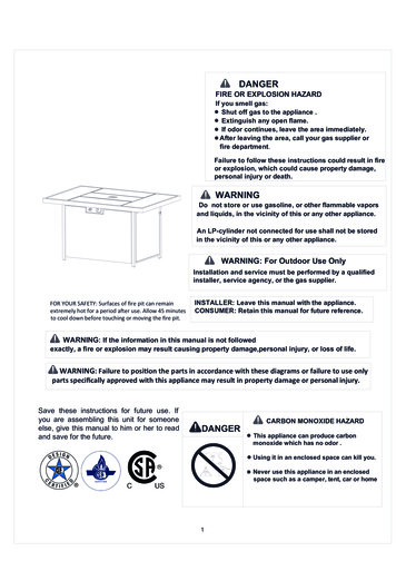
ASSEMBLY 3201221419182522242026HARDWARE LIST 182PCSE6.5x6026PCSJ4x581PCPAGE 4 OF 12
ASSEMBLY INSTRUCTIONSPARTS LISTWF28589411pcTop cross bar21pc1415Bottom front bar3pcs3Top & bottom back bar41pc1617Front side rails51pcLeft guard rails support71pc191pc202pcsTop & botoom guard rails supportBack guard rails support2pcs10Front top cross bar112pcsBack top cross bar12136pcsMiddle & bottom bars2pcsBottom barsRight front leg1pcLeft back leg1pcLeft back leg1pc1pcRight stair side or left stair side3pcsStep stair side21Slats1pc91pcLeft stair side or left stair sideRight guard rails support8Left front leg18Back side rails61pc2223242526PAGE 5 OF 1214pcs1pcSlide left leg1pcSlide right leg1pcSlide panel4pcsSlide support1pcSlide bottom panel
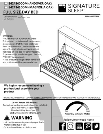
ASSEMBLY INSTRUCTIONSStep 1HC12 x2HHCH12 x2J13 x1H17 x1HCCHH13 x116 x112 x2JCC15 x1HHH12 x1CH14 x1CHJCC16PCS6.5x100J4x70HØ10x401PC20PCSStep 211 x2H10 x2JJHCCC6.5x1002PCSJ4x701PCHPAGE 6 OF 12Ø10x402PCS
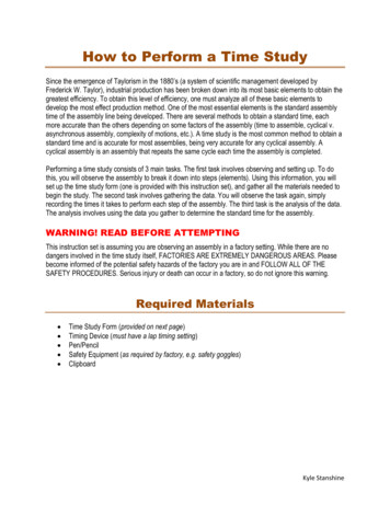
ASSEMBLY INSTRUCTIONSEStep 3JEHJEEHJEHHHØ10x40H4PCSJ4x581PCE6.5x604PCSStep 4DDH1 x1DDJF5 x1JDHHH3 x3DDF4 x12 x758PCSPAGE 7 OF 12
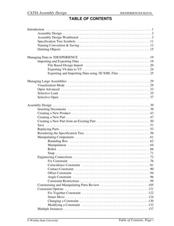
ASSEMBLY INSTRUCTIONSFirst attach 2pcs part 21 to the front and end of the frame between headboard.Then attach the remaining part 21 equidistantly between headboardStep 5AA21 x14A9 x1A3-1/8"3-1/8"Note : Do not lock the screws of the bed slats to the outermost edge of the bed slats, you needto leave a certain space at the edges, otherwise it will cause the board to breakAØ4x3031PCSPAGE 8 OF 12
ASSEMBLY INSTRUCTIONSStep 619 x1HEH18 x120 x1EHEEHJJHHE20 x2EHEJ4x581PCE6.5x606PCSHØ10x406PCSStep 7HD7 x1HHDJH8 x2JDH6 x1D6.5x804PCSJ4x581PCHØ10x404PCSPAGE 9 OF 12
ASSEMBLY INSTRUCTIONSStep 8GJJEGGJJEEEG1/4x354PCSJ4x581PCE6.5x604PCSPAGE 10 OF 12
ASSEMBLY INSTRUCTIONSStep 9E24 x1IJHEBIHIBBE25 x2HJ23 x1EEEEH25 x2EHH22 x1E26 5x60PAGE 11 OF 121PC12PCS
ASSEMBLY INSTRUCTIONSStep 10BBBPAGE 12 OF 12Ø4x152PCS
ASSEMBLY INSTRUCTIONS PAGE 8 OF 12 First attach 2pcs part 21 to the front and end of the frame between headboard. Then attach the remaining part 21 equidistantly between headboard AØ4x30 31PCS Step 5 3-1/8" 3-1/8" Note : Do not lock the screws of the bed slats to the outermost edge of the bed slats, you need