Transcription
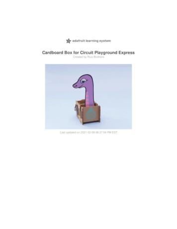
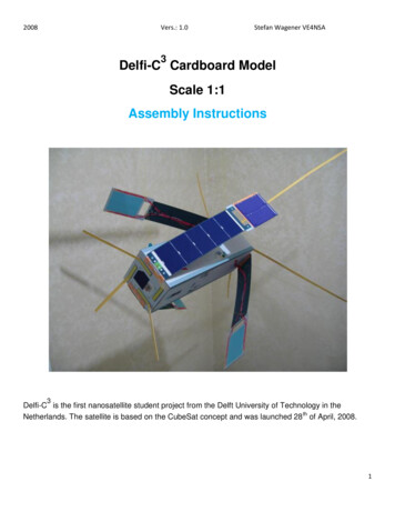
2008Vers.: 1.0Stefan Wagener VE4NSA3Delfi-C Cardboard ModelScale 1:1Assembly Instructions3Delfi-C is the first nanosatellite student project from the Delft University of Technology in theNetherlands. The satellite is based on the CubeSat concept and was launched 28 th of April, 2008.1
2008Vers.: 1.0Stefan Wagener VE4NSAHints and TipsThis 1:1 scale model of Delfi-C3 was created using Adobe Illustrator C3 and all files were converted to pdf fordistribution. In order to maintain the exact size and allow for matching and fitting pieces it is important thatscaling of your printer is turned OFF. No “fit to page or percentage” other than 100%. To help you with theprinting, I have included a ruler on some pages that will allow you to measure the print size. 6 cm on the papershould really be 6 cm (not 6.1 or 5.9).The use of pfd files has several advantages. It allows for easy distribution of files that are not very big. You canprint out parts and pieces as often as you like (which becomes very handy if you need to redo a part) and youalso can select the type of paper you want to use or have.Many people refer to these types of models as “paper models” however regular paper is hardly used. Thesemodels are generally printed on a heavy paper so called "card stock” or “cover stock”. I use 67lb (148g/m2)card stock. It is heavy enough to give the internal frame parts enough support and will work nicely for a laserprinter (black and white). The regular size of the stock paper is 8½” x 11” (216 x 279mm). This is the “letter”format paper I have available. For Europe and other countries A4 paper size is used 8¼” x 11¾” (210 x297mm). The files will work for both paper sizes, however, keep in mind the model was designed on 8½” x 11”“letter size and if you use A4 the printer might want to scale it. Turn it off.Now, since Delfi-C3 is 34cm long, the side panels will require longer paper or cardstock. The files for the sidepanels were designed for “legal” size paper which is 8 ½” x14 (216 x 356mm). Although that allowed for thedesign of the side panels in one piece, it also created a number of problems. First of all, since I recommendusing “photo paper” for printing all color pages and pieces, it is almost impossible (or expensive) to find “legal”size photo paper. When I printed the panels on regular paper (legal size), the colors, as anticipated, looked dulland since I don’t even have “legal” size heavy card stock, once glued, the paper warps or “leaks” glue stains tothe outside. Consequently, I am now using regular size (letter) heavy duty photo paper for printing (whichmeans your A4 photo paper will work).However, the panel pieces will be cut off during printing. Short of re-designing these panels in two separatepieces (for two pages), I print the same panel twice, one time upside down. Now I have the panel twice withboth ends cut off. You can now cut the panel with an X-Acto knife along one of the lines and use the resultingpieces for assembly. Look for the small arrows next to panel for a proposed cutting line.2
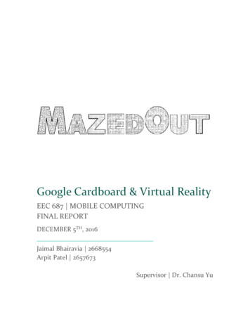
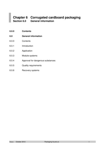
2008Vers.: 1.0Stefan Wagener VE4NSAAt one point I probably will redesign the model and have two pieces for each panel. Unfortunately, AdobeIllustrator does not allow the easy select and cut like Photoshop because of all the different layers and parts.(Or maybe, I haven’t figured it out).I highly recommend the following tools and supplies: an X-Acto knife (change the blade frequently and use it for all straight cuts); a cutting board (use a bread board, or one of the "self-healing" boards); various sizes of metal binder clips, clothes pins, or small clamps; rubber bands etc; Color Printer (Inkjet) and paper (I used Canon “Matte Photo Paper MP-101”. It is 45lbs paper (170g/m2)and designed for arts and crafts. It glues well. Glue: I am not a big fan of wet glues and prefer the glue sticks. The new “UHU Glue Stick” #99115)works great for me. It’s sold as UHU Extra Power at Staples (US or CA) Super Glue; the quicker it glues the better; Cardstock; heavy paper of your choice; Photo paper of your choice, some photo paper is designed for “art” projects; Cardboard; Use regular card board not the corrugated material.Important:Before you bend any pieces you will need to score them on the back.Scoring is the process of indenting the cardboard material without braking or cutting it and will allow for easyfolding along the scoring line.Before folding any part, score the fold lines with a (dead) ballpoint pen on the backside of the part. Figure 1shows one of the “medium size frame” support bars cut out with a second frame piece turned around andscored on the back along the fold lines. None of these parts will be visible later on, so if you use a workingballpoint pen, that’s okay.White edges:One of the “negative” side effects of paper models is that you can only color the front (or the back of the page)but at the moment you cut paper, the thin edge is white.3
2008Vers.: 1.0Stefan Wagener VE4NSAFor many that is very annoying since the white edge will show. For that reason, have a black (or whatevercolor) pencil available and carefully going around the edge of the cut our part, stain it black (or whatever color).It will look much more “professional”.Figure 1 (Scoring lines on the back of a “medium frame” support piece)Once you score the paper or cardboard, you will see how easy it is to exactly fold that part along the scoringline without actually breaking the paper.Assembly Instructions1.0FrameLook at the pages 7-9 of the model pdf file. Page 7 has to be printed 4x and pages 8 and 9 two times,respectively. Cut out the parts and score the pieces on the back. Fold them, and glue them together. Makesure they stay straight during gluing and drying. Working patiently and exactly will pay off at the end. Themedium parts support the center; the small parts support the top and bottom of the frame. See pictures below:4
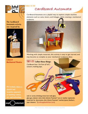
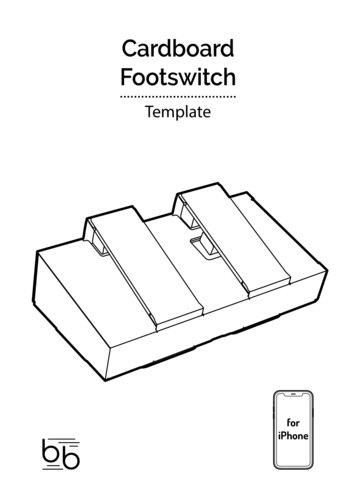
20082.0Vers.: 1.0Stefan Wagener VE4NSASolar PanelsThe solar panel parts are on Pages 1-3. Print each page 4x on photo paper and carefully cut out the pieces (XActo knife).Figure 7: Solar panel piecesThe actual solar cells will be glued on top of the lower panel piece in-between the dashed lines. By attachingthem separately, it allows the panel to have some 3D structure or depths to it.5
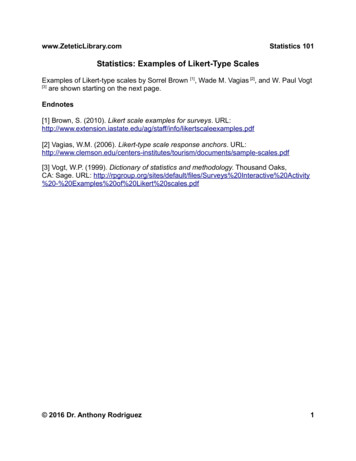
2008Vers.: 1.0Stefan Wagener VE4NSAYou can even glue the solar cells on a separate sheet of cardboard first, to give them even more depths.Watch the order of how the pieces are glued together:1. Glue the upper solar panel ( the experiment) behind the top of the lower solar panel (Fig 8);2. Attach the back panel (Fig 9)Optional: glue some additional cardboard behind the lower part of the solar panel for structural support(Fig 11); it will be covered with the back panel.3. Attach the back of the upper solar panel (Fig 10).Figure 8, 9, 10 Solar panel assemblyFigure 11 Additional piece of cardboard for support4. Attach the solar cells on the front of the panel in between the dashed lines. As an option you can attachthe solar cells to additional cardboard first.6
2008Vers.: 1.0Stefan Wagener VE4NSAFigure 12, 13 Solar Panels assembled3.0Frame Side PanelsThe four side panels which attach to the frame are located on pages 4-6. Before you print them out keep inmind that these pages are larger! The files for the side panels were designed for “legal” size paper which is 8½” x14 (216 x 356mm). Most folks (like me) will use regular (letter or A4) photo paper to print those pages.Fortunately, the Adobe Acrobat reader software allows you to rotate a page.Figure 14: “Rotate view” in Adobe Acrobat Reader7
2008Vers.: 1.0Stefan Wagener VE4NSAFigure 15: Printing the rotated page. The lower portion of the page (grey area) will be cut off.In this way you print out the page first in its original layout. Then you rotate it and print out the other end of thepage. Make sure your printer also prints the page after rotation! Each time the printer will cut off the bottompart of the page.Once you cut the pieces at the proposed cutting line you can attach them together (tape on the rear) and youhave a complete side panel (Figure 16).Figure 16: (Side and solar panel)8
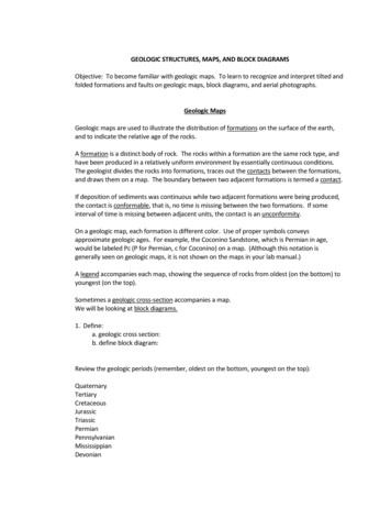
20084.0Vers.: 1.0Stefan Wagener VE4NSABottom and Top Panel & Hinges1.The top and bottom piece are found on Page 10. Cut them out. Don’t forget to stain the edges(see hints and tips).2.Glue the top of the solar panel hinges (Page 11) on a piece of cardboard and cut them out.Score the cardboard on the back (right along the middle). That will make it so much easier tobend the hinge later. Now cut out the bottom part of the solar hinges and glue them on the backof the cardboard (like a sandwich). In this way, you don’t see the cardboard and the hinge getsadditional support and strength.3.Glue the hinges to the bottom and top panel.Figure 17-19: Panel and hinges5.0AntennasThe 2m (145MHz) antennas are found on page 12. Look at Page 14; it has some drawings outlining theconstruction of the antennas. Since we are using cardstock and the antennas are pretty long we have to buildin some additional support. For that reason, I used 20 gauge steel wire. It is stiff enough to give support andthin enough for embedding it in between the parts.1. Cut out the bottom pieces and lay them on top of each other in front of you (the yellow side down). Thegrey part is used for the bottom support (attached to the satellite).2. In order to glue them together, cut out the center strips and glue them along the inside edge of thebottom pieces. You will have a 1mm gap in the middle which will hold the wire later (see Fig. 20).9
2008Vers.: 1.0Stefan Wagener VE4NSAFigure 20-21: Assembly of the 2m antennas3. Since the two bottom pieces have a combined length of 45.8cm (minus the grey part) and the centerstrips (Part #3 on page 12) are 15.3cm each, they will overlap the two bottom pieces (Fig 21). This isintended since that will hold the two bottom pieces together.4. Once all the strips are attached, superglue the wire inside the groove. As you can see in Fig 22, I usetape to hold things in place.Fig 22: Steel wire10
2008Vers.: 1.0Stefan Wagener VE4NSA5. After the wire is in place attach the top parts and the bottom support parts (which will be glued onto themodel). See page 23 of the model pdf fileOnce you finished the 2m antennas, assemble the 70cm antennas (Page 13). The small diagram explains theprocess. It is important to carefully score the back of the antenna parts before folding them over and gluingthem together. Because these pieces are short enough, the cardstock material gives them enough support andno additional wire is needed.Final assemblyBefore attaching the side panels to the frame take a black marker and stain the all edges of the frame black.Since somewhere on your model, a small part of the frame might be showing once all pieces are attached, theblack background makes it look nice (Fig 23).At this point, I have not designed a matching stand for the model and therefore will have it “float”, hanging up. Itis helpful to attach two small cardstock pieces on the long edges before you glue on the side panels. This willallow you attach a string later (Fig 23). The side panels will cover it up nicely.Fig 23: Stained edges and string tab attached to the ledge11
2008Vers.: 1.0Stefan Wagener VE4NSAWatch for the correct orientation of the side panels and the top and bottom panels. I found it easier to attachthe solar panels and hinges to the bottom and top panel first before I mounted them to the frame (Fig 24). It iseasier to bend the hinges now to give the solar panels close to a 45 degree angle. By the way, Figure 24shows an older bottom panel with the red cover for the AWSS. The most recent design has both bottom andtop panel identical.Fig 24: Solar panels attached to bottom panelOnce you have the all the panels attached, bend the antennas slightly at the lower portion and superglue themto the satellite. I had the model hanging up for that one. Take your time with this procedure. Superglue isnormally a onetime shot.12
2008Vers.: 1.0Stefan Wagener VE4NSAFigure 25: Attached antennasThat should do it!Since this is the first cut of the instructions, I probably missed something here and there and will have to makecorrections along the way. Your feedback and experience is greatly appreciated. You can contact me at:VE4NSA@amsat.org and please consider a donation to AMSAT for the next satellite project.Most of all have fun!73, Stefan VE4NSAAcknowledgements:I am very grateful for the support and help received by:Geert Brouwer and Wouter Jan Ubbelsfrom Delft University, Faculty of Aerospace Engineering, Space Systems Engineering.Their advice and the availability of detailed construction information allowed me to design a hopefully accuratemodel.For more information and current status of Delfi-C3 visit the website at:http://www.delfic3.nl/13
Assembly Instructions Delfi-C 3 . and designed for arts and crafts. It glues well. . line without actually breaking the paper. Assembly Instructions 1.0 Frame Look at the pages 7-9 of the model pdf file. Page 7 has to be printed 4x and pages 8 and 9 two times, respecti