Transcription
IntroductionHybrid is a high-definition software synthesizer that combines the warmth of legendary analogsynths with a full range of 21st century digital manipulation capabilities. The result is the best ofboth worlds—a virtual instrument with a comprehensive set of precisely adjustable parametersthat can sound like a synth you remember or something no one has ever heard before.2
System Requirements and Product SupportFor complete system requirements, compatibility information, and product registration, visit theAIR website: www.airmusictech.com.InstallationWindows 1.Double-click the .exe installer file you downloaded.2.Follow the on-screen instructions.Note: Hybrid uses PACE copy protection, so it will install the PACE InterLok driver on yoursystem if you do not already have it. As most audio software uses PACE copy protection,though, this is probably already installed on your system.Mac OS X1.Double-click the .pkg installer file you downloaded.2.Follow the on-screen instructions.3
Understanding HybridSubtractive vs. Wavetable SynthesisHybrid's unique sound engine uses a combination of classic "subtractive" and digital"wavetable" synthesis to give you a very wide palette of sounds.Subtractive Synthesis:This process of generating and shaping sound is called subtractive synthesis because it dealsmainly with removing frequencies from the highly harmonic waveforms. Subtractive synthesisgenerally starts with one or more oscillators producing electronic waveforms with rich harmoniccontent. Successive modules (such as filters and amplifiers) then shape this sound by varyingthe harmonic content and level. Additional modules (such as Envelope Generators and LowFrequency Oscillators) are then used to shape and vary the sound over time (a process knownas "modulation").Wavetable Synthesis:Wavetable synthesis became popular with the first digitally controlled synthesizers. A wavetableis a file that consists of 64 different single-cycle waveforms. A digital oscillator runs throughthese waveforms to create complex and vivid sounds. Wavetable synthesis is usually combinedwith subtractive synthesis for additional sound-shaping.The Hybrid Synthesizer and its "Parts"Before getting into the details, it's important to understand that Hybrid actually has twocomplete synthesizer cores that work together. These cores are called "Parts" (or "Part A" and"Part B"). You can use these Parts to create things like velocity layers, keyboard splits, or tospread different sounds across the stereo field. The controls for Parts A and B are identical.You can save individual Parts on the Part Presets page. Alternatively, you can save complete"patches" (including both Parts and all other Hybrid parameters) by using the Save button atthe top right of the instrument. Both of these will be explained later in this guide.4
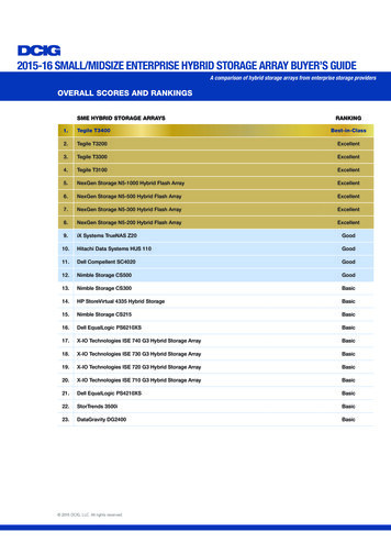
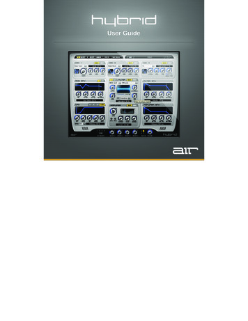
Hybrid's Graphical InterfaceHybrid has a straightforward user interface that can be broken down into three sections. Thetop ("Setup") and bottom ("Master") sections are always visible; the Control Pages area (in themiddle) changes depending on what you have selected. Setup Section: This area lets you load and save Hybrid patches as well as navigate toany of the Control Pages. This section is described on the next page. Control Pages: This area shows one of the seven Control Pages where you can programHybrid sounds and effects. This User Guide has a separate chapter for each of the pages. Master Section: This area has "global" controls including Master Volume and theinnovative "Morph" knobs. To learn more, see Master Section later in this chapter.5
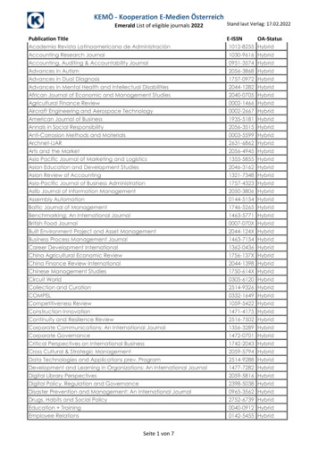
Setup SectionThe left half of the Setup section (items 1-5 above) let you access Hybrid's seven ControlPages. The right half is for saving and loading complete Hybrid sounds ("Patches").1.Part A/B Page – Provides controls for all sound generating parameters of Part A or B,such as settings for its oscillators, filters, amplifiers, envelopes, and LFOs.2.Part A/B Seq – Provides controls for the sequencer of Part A or B. The settings includethe sequencer lanes for Note, Velocity, Control 1 and Control 2, and additional Playbackmodes (such as arpeggios and MIDI phrases).Note: Parts A and B are identical and provide the same controls on both their Part andSequencer pages.3.Common Page – Provides controls for adjusting the overall pitch and voice managementacross all Parts. In addition, there are global settings governing the operation of Hybrid.4.Effects Page – Provides controls for the Part A and B insert effects as well as the mastereffects applied to the whole patch.5.Part Presets Page – Provides controls for loading and saving presets of Part A and B andgives access to the most commonly edited synthesizer parameters.6
6.Save/Load Section – This section lets you load and save sounds. Loading Sounds: To load a sound, click the screen to bring up a categorized list ofHybrid sound patches. You can also use the arrow buttons to the right of the patchname to quickly shift between sounds. Saving Sounds: To save a sound, click the Save button. If you wish to quicklyoverwrite the file you are currently working on without changing the file name orbringing up the file browser, you can do so by shift-clicking the Save button.7
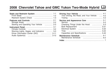
Master SectionThe Master Section the innovative "Morph" controls (items 1-2) as Part on/off switches and amaster volume control.1.Edit Morph Controls – The 1-4 Edit Morph buttons activate the editing and displaying ofassigned parameters of a Morph group. The Clear button deletes all assignments of theedited Morph group. These controls are covered in detail in the next section of this guide.2.Morph Knobs – You can assign each of these knobs to control many parametersthroughout Hybrid. These controls are covered in detail in the next section of this guide.Note: All Morph group assignments and settings are saved and restored with the patch.3.Part On – These buttons let you switch Parts A and B on and off. A lit button indicates thePart is active.4.Volume – Sets the master output volume of Hybrid.8
Morph ControlsHybrid has an innovative "Morph" control system that gives you easy and instant access tomany parameters throughout the synthesizer. This system lets you assign nearly any Hybridcontrol (knob, fader, envelope, etc.) to a "Morph group" and then use one knob to control all ofthe desired parameters simultaneously. This allows you to make very complex changes in yourHybrid sounds by turning a single knob.To assign a knob or fader:1.In the Master section, select a Morph group by clicking one of the 1-4 Edit Morph buttons.2.Hold Shift while you click-and-drag the control you want to assign, such as Filter cutoff.3.Set the control's morph range. To specify a morph positive in direction, Shift-drag the control, as you would toincrease its value. To specify a morph negative in direction, Shift-drag the control, as you would todecrease its value. The indicator on your knob of a fader marks the start value of the morph. The yellownext to a knob or fader indicates the morph range and direction.You can make adjustments and assignments as long as you are in Edit mode.4.When you are finished, click the 1-4 Edit Morph button to deactivate Edit mode.Note: A Hybrid control can only be assigned to one Morph group at a time.9
To assign a graphic control:1.Choose a Morph group by clicking one of the 1-4 Edit Morph buttons.2.Hold Shift while you click and drag the control you want to assign.3. With envelopes, the yellow envelope represents the values the envelope morphs to.The blue envelope in the background represents the original envelope. Use Shiftdrag to change the yellow envelope to achieve a morph. Dragging without holdingShift adjusts the blue envelope. With LFOs, Shift-click the rate cursor and drag left to increase the rate or drag right todecrease the rate through morphing. A yellow bar represents the morph range anddirection.Deactivate the Edit Morph button of the Morph group to finish editing.Note: Graphic controls can only be assigned to one Morph group at a time.To view or edit morph ranges:1.Select a Morph group by clicking one of the 1-4 Edit Morph buttons.2.Select a Control Page that contains the control that you're interested in viewing or editing.Yellow lines appear next to all controls that are assigned to that Morph group.3.To change the morph range: To change the end value, Shift-drag the control. To change the position of the morph range (start and end value), Shift Alt-drag(Windows) or Shift Option-drag (Mac) the control. Dragging without holding Option changes the start value of the morph range.You can make adjustments and assignments as long as you remain in Edit mode.4.When you are finished editing, click the 1-4 Edit Morph button to deactivate Edit mode.10
Morph Group ControllerMIDI controllers give even better control over Hybrid's Morph groups. For example, use theModulation Wheel or Aftertouch from your MIDI keyboard to have immediate control overmorphs.To assign a MIDI controller to a Morph group:1.Select the Common page.2.Make one of the following settings in the Morph Assign section: Off: Uses only the morph rotary control on the plug-in surface. Mod Wheel: Uses the modulation wheel to control the morph (CC# 01). Aftertouch: Uses channel pressure to control the morph. Pitch Bend: Uses pitch bend to control the morph. Foot: Uses the MIDI pedal to control the morph (CC# 04). Breath: Uses the breath controller to control the morph (CC# 02).Note: You can also assign a continuous controller to the morph rotary controller with the MIDIcontroller mapping. The difference is the settings above save with the patch and the MIDIcontroller mapping saves only with the session.11
MIDI Controller MappingHybrid lets you assign standard MIDI controllers to virtually any parameter so that you cancontrol Velvet from a MIDI controller in real-time.To assign a MIDI controller to a parameter:1.Right-click (Windows or Mac) or Control-click (Mac) a control.2.Do one of the following:a.Select the desired MIDI controller from the Assign sub-menu.b.Select Learn, and move the desired control on your MIDI controller. The parameter isautomatically assigned to that control.To un-assign a MIDI controller:1.Right-click (Windows or Mac) or Control-click (Mac) a control.2.From the menu that appears, select Forget.12
Part PagesThe Part A and Part B pages give detailed access to all sound-generating parameters ofHybrid.Note: The two pages have identical controls, so this chapter applies to both Parts.This Page may appear overwhelming at first, but not to worry—the layout of the variousmodules (such as Oscillator, Filter, Amplifier, etc.) follows Hybrid's signal flow. Signals start atthe top with the three oscillators and flow downward through the filter and finally the Amplifier.The Filter and Amplifier modules have dedicated envelopes located to their right. Finally, thereare freely assignable Modulation envelopes and LFOs are on the left side of the page.13
Overview of Signal FlowEach Hybrid Part has three independent Oscillators along the top of each Part page. Theseoscillators feed into a Filter section containing two separate filters. The output of the Filtersection is then fed into an output amplifier that controls the volume of the Part.The Filter(s) and Amplifier have dedicated envelopes located directly to the right of eachmodule. These envelopes are "hard-wired" to control the Filter or Amplifier.Finally, to the left of the Filter and Amplifier, you'll find two Mod envelopes and four LFOs thatcan be assigned to control a variety of different parameters.14
OscillatorsOscillator OverviewThe two main oscillators, Oscillators 1 and 2, offer various waveforms and provide tuningcontrols calibrated in semitones and cents. Each waveform is unique in its function and sound.The Oscillator Type drop-down menu selects the basic waveform of the oscillator, and theShape control provides further control over the waveform's tone color.Oscillator 3 primarily supports Oscillator 1 and 2; it transposes in octave steps and providesclassic waveforms like sawtooth, square, and triangle as well as Sub oscillator and Noisegenerator. The Sub oscillator has a square waveform and follows the pitch of Oscillator 3 butone octave lower. The Noise generator outputs white noise. A blend of Oscillator 3 with noisealso serves as a Modulation source for the filter.Note: Each oscillator contains two pages: Main and Mod. These pages are accessed byclicking the corresponding buttons at the top-right of each module. Both of these pages aredescribed in the following pages of this section.15
Oscillators 1-2Oscillators 1-2 (Main Tab)1.Oscillator Type – The drop-down menu at the topselects the oscillator type (the basicwaveform and algorithm). The Wavetableand Multi-wave options have sub-optionsthat can be selected by clicking the smalltriangle under the display.2.Shape – Selects the tone color of the Oscillator. For someoscillator types, higher settings of this control can result inradical sonic effects. A setting of 0% is neutral and has noeffect on the sound. The function of this knob variesdepending on your Oscillator Type selection: The pitch ratio between master and slave of a sync oscillator (Saw Sync andSqu Sync types) The pitch ratio between carrier and modulator of a cross modulation oscillator(Saw CM and Squ CM) The amount of detuning between the waves of a Multi-Wave oscillator The pulse width of a square wave (Squ PWM) The wave index of a wavetable oscillator (Wavetable)Tip: For more detailed descriptions of the available waveforms, please see Appendix A:Oscillator 1-2 Type Descriptions.3.Semi – Transposes the pitch of the oscillator up or down by semitones. The control rangeis from –24 to 24 semitones (two octaves down or up). Use this feature to tune theoscillator to an interval such as a perfect fifth (-7 or 7) for interesting tonal effects.4.Cents – Sets the pitch of the oscillator in hundredths of a semitone. The control range isfrom –50 to 50 cents. Use this control to detune an oscillator relative to the otheroscillators. Detuned oscillators animate and thicken the sound.5.Level – Sets the volume of the oscillator.16
Osc 1-2 (Mod Tab)1.Oscillator Type – The drop-down menuat the top selects the oscillator type (thebasic waveform and algorithm). TheWavetable and Multi-wave optionshave sub-options that can be selectedby clicking the small triangle under thegraphical display.2.Modulation Matrix – This area lets youconnect the various modulation sources(such as an envelope or LFO) to thevarious parameters of the oscillator(such as the Pitch or Shape knob). Youcan also set how strongly you want the modulation source to affect the destination. Destination: Click the small triangle at the left edge of this section to select theparameter that you would like to control (known as the "destination"). Source: The drop-down menu in the middle determines which "source" will beused to modulate the destination. There are many options you can choose from(any of the envelopes or LFOs, data from the sequencer, or incoming MIDIdata). Amount: The horizontal fader on the right determines how strongly the sourcemodulates the destination, from -100% to 100%. Note that setting this fader to0% will mean no modulation will take place.17
Oscillator 3Oscillator 3 (Main Tab)The Oscillator 3 Main page provides controlsfor Oscillator 3, the Sub oscillator, and theNoise generator. Oscillator 3 features theclassic sawtooth, square, and trianglewaveforms and can serve as a Modulationsource for Filter FM. In general, its pitchfollows that of the Part. The Sub oscillatorgenerates a square wave that follows thepitch of Oscillator 3 but one octave lower.1.Oscillator Type – Selects the wave shape of Oscillator 3.2.Octave – Transposes the pitch of the oscillator up or down by two octaves.3.Level – Sets the volume of Oscillator 3.4.Sub – Sets the volume of the Sub oscillator.5.Noise Level – Sets the volume of the Noise generator. The Noise generator provides fourdifferent colors of noise: A (White Noise): Is a combination of equal amounts of all audio frequencies. Ingeneral, white noise delivers a bright hiss with no pitch information, and can beused to synthesize non-pitched sounds (such as drums or wind effects). B (Blue Noise): Is filtered white noise that is brighter, thinner and cleaner. C (Mod): Is white noise with amplitude modulation by Oscillator 3 for a pulsing,grating sound. D (Crackle): Provides sparse noise, like a dusty vinyl record. You can useCrackle to add a vintage character to the sound.18
Osc 3 (Mod Tab)This page has three destination controls formodulating Oscillator 3, Sub oscillator, andNoise generator. The destinations can beaddressed multiple times.Note: Since Oscillator 3 always follows thePart's pitch, it is not possible to modulationthe pitch of this oscillator.1.Oscillator Type – The drop-down menuat the top selects the oscillator.2.Modulation Matrix – This area lets youconnect the various modulation sources(such as an envelope or LFO) to the various parameters of the oscillator (such as theLevel or Noise knobs). You can also set how strongly you want the modulation source toaffect the destination. Destination: Click the small triangle at the left edge of this section to select theparameter that you would like to control (known as the "destination"). Source: The drop-down menu in the middle determines which "source" will beused to modulate the destination. There are many options you can choose from(any of the envelopes or LFOs, data from the sequencer, or incoming MIDI data) Amount: The horizontal fader on the right determines how strongly the sourcemodulates the destination, from -100% to 100%. Note that setting this fader to0% will mean no modulation will take place.19
FilterHybrid's analog modeling filter block contains two independent filters. For each of these twofilters, you can choose from 23 different Filter types ranging from classic 4-pole low-pass tocompletely new and unique types. The filter types are described in Appendix B.All Filter types include Cutoff and Resonance controls. The Saturation control adds thecharacteristic grit of an overdriven filter to the sound. By default, cutoff is modulated from adedicated Filter envelope, located directly to the right of the filter module. The Env (Envelope)knob adjusts the depth of this modulation.Note: The filter module contains two separate filters that can be viewed by clicking the 1 and 2buttons at the top-left of the page. Each of these filters has two pages: Main and Mod. Thesepages are accessed by clicking the corresponding buttons at the top-right of the module. All ofthese pages are described in the rest of this section.20
Filter (Main Tab)1.Mode – Displays and selects the Filter mode, either DCF or VCF. DCF mode (DigitallyControlled Filter) emulates a sharp and precise-sounding digital filter. VCF mode (VoltageControlled Filter) emulates the warm, analog sound of the filters in classic analogsynthesizers.2.Type – Displays and selects the Filter type and structure. Capital letters describe the Filtertype (for example, "LP" stands for "low-pass"). The number indicates the attenuation bynumber of poles (one pole equals an attenuation of 6 dB/oct). If a mode combines morethan one Filter type, they are both listed, separated by a plus ( ) sign.3.Cutoff – Adjusts the cutoff frequency of the filter. Depending on the Filter type,frequencies above, below, or above and below the cutoff frequency are attenuated.4.Resonance – Emphasizes the frequencies around the cutoff. With increasing values, thetonal color changes from an open neutral sound, to a nasal sound, to a ringing tone,caused by self-oscillation of the filter. Values above 90% usually drive the filter into selfoscillation.21
5.Gain – Adjusts the gain of the filter section. This can be used to compensate forreductions in signal level due to filtering.6.Env – Controls the cutoff modulation from the Filter envelope. Higher settings of thiscontrol cause the filter to open wider.7.Dist – This section adds color to the filtered sound by using the integral distortion of thefilter. There are seven distortion types, each with a distinct tonal character. The drop-downmenu lets you select the distortion type. The horizontal slider above the menu sets theamount of filter saturation.The sonic effects range from slight overdrive to hard-distorted sounds with subharmonics.Higher values introduce more extreme effects. The graphic display in the middle of theFilter section indicates the amount of saturation that is used.ModeDescriptionOverdriveDistortHard ClipCreates a soft, tube-like clipping.Creates a harder, brighter clipping.Creates a hard, bright, transistor-likeclippingCreates a gentle distortion, which retainsthe character of the input.Reduces the bit depth, creating deliberatealiasing.Reduces the sample rate, creatingdeliberate aliasingRectifyBit CrushResample22
Filter (Mod Tab)This page provides the controls for Filter FM and three sets of modulation source anddestination. Each destination can be set to Cutoff, Resonance, and FM depth.1.Modulation Matrix – This area lets you connect the various modulation sources (such asan envelope or LFO) to the various parameters of the filter (cutoff, resonance, or FM). Youcan also set how strongly you want the modulation source to affect the destination. Destination: Click the small triangle at the left edge of this section to select theparameter that you would like to control (known as the "destination"). Source: The drop-down menu in the middle determines which "source" will beused to modulate the destination. There are many options you can choose from(any of the envelopes or LFOs, data from the sequencer, or incoming MIDI data) Amount: The horizontal fader on the right determines how strongly the sourcemodulates the destination, from -100% to 100%. Note that setting this fader to0% will mean no modulation will take place.23
2.Key Track – Allows for cutoff modulation by MIDI note number. The control range is from–100% to 100%. With a low-pass filter and no key tracking applied, higher notes sounddarker as the pitch moves beyond the cutoff. When key tracking is set to 100%, the pitchof the played MIDI note modifies the Filter cutoff in the same direction. Higher notesincrease the cutoff frequency and thus avoid tonal changes over the entire keyboardrange. Settings in between result in varying degrees of tonal change.3.FM Mix – Blends the modulation signal between Oscillator 3 and the Noise generator. Asetting of 0% sends only Oscillator 3 to the cutoff. A setting of 100% sends only noise tothe cutoff. Use Oscillator 3 for a more regular modulation. Noise generates a randommodulation with no pitch information.4.FM Depth – Sets the amount of Filter FM. The sonic effect depends on the modulationsignal, which is specified using the FM Mix control and the wave shape of Oscillator 3. Theamount of Filter FM can also be modulated with the filter's modulation source anddestination.Creating a Filter FM Sound:Modulating the cutoff at the audio rate produces Filter FM. Frequency modulation has thereputation of being hard to use. However, if you keep the following rules in mind, this feature isas easy to use as any other in Hybrid.1.Filter FM is best used when the filter is self-oscillating. Therefore, please make surethe Resonance control on the Main page is turned fully clockwise.2.The higher the frequency of the modulating oscillator, the richer the sidebands. Usethe Octave control of Oscillator 3 to raise the pitch. Turn the levels of Oscillator 3 and theSub oscillator all the way down to make them inaudible.3.Without moving the Cutoff, you will produce a static sound. Modulate the cutoff withthe Filter envelope to sweep through the sidebands.24
Filter 2Hybrid's second filter can be viewed by clicking 2 at the top-left of the Filter module. On thesecond filter, all of the controls on the Main and Mod pages are identical to those of the firstfilter, except one:1.Routing – This drop-down menu lets you select how signals flow from one filter to theother. The options are as follows:ModeDescriptionOffSerialTurns the second filter off.Signal flows from Filter 1 to Filter 2.Incoming signal is fed to Filter 1 and Filter2 simultaneously and is combined.Filter 1 is applied to the left channel;Filter 2 is applied to right channelOscillator 1 feeds Filter 1;Oscillator 2 and 3 feeds Filter 2ParallelL/ROsc25
Amplifier SectionThe Amplifier section controls the loudness of a Part and its position in the stereo field. Inaddition, it has activation buttons for the effects Inserts and knobs to control how much signal issent to three Master Effects.The amplifier is hard-wired to the Amplifier envelope (located directly to the right), which shapesthe sound dynamically. "Hard-wired" means the envelope affects the amplifier always at fullintensity. Additional modulations, such as tremolo or panorama modulations from LFO, can beselected on the Mod page.26
Amplifier (Main Tab)On its Main page, the amplifier provides the controls for level and position, the two activationbuttons for the effects Inserts, and the three sends for the master effects. The controls for Pankey tracking and random modulation—and the three modulation sources and destinations—areset on the Amplifier's Mod page. The Amplifier section provides the following controls:1.Level – Controls the volume of the Part.2.Pan – The graphic control displays and sets the output signal's position in the stereo field.Click and drag the vertical blue line to change the position.3.Ins 1-2 – Activates and deactivates the effects inserts of the Part. Click each button toswitch the insert on or off. The insert is active when its button is lit.4.Chorus – Sets how much of this Part is sent to the Chorus Master Effect.5.Delay – Sets how much of this Part is sent to the Delay Master Effect.6.Reverb – Sets how much of this Part is sent to the Reverb Master Effect.Tip: To learn more about effects Inserts and the Master Effects section, please refer to theEffect Page: Master Effects section of this guide.27
Amplifier (Mod Tab)This page provides controls for two pre-assigned stereo field modulations, and three sets ofmodulation destinations and sources.1.Modulation Matrix – This area lets you connect the various modulation sources (like theSequencer or an LFO) to the volume and pan parameters of the Amplifier. You can alsoset how strongly you want the modulation source to affect the destination. Destination: Click the small triangle at the left edge of this section to select theparameter that you would like to control (known as the "destination"). Source: The drop-down menu in the middle determines which "source" will beused to modulate the destination. There are many options you can choose from(any of the envelopes or LFOs, data from the sequencer, or incoming MIDI data) Amount: The horizontal fader on the right determines how strongly the sourcemodulates the destination, from -100% to 100%. Note that setting this fader to0% will mean no modulation will take place.28
2.Key Track Pan – Changes the Part's position in the stereo field with MIDI note number.The control range is from –100% to 100%. The center point is in the keyboard center(middle C) and marks the center position in the stereo field. Set a positive value to movethe sound left as you play low notes and right as you play higher notes. Specify a negativevalue to move the sound right as you play low notes and left as you play higher notes.3.Random Pan – Use this control to offset the sound in the stereo field randomly each timeyou play a note. Higher values produce greater offsets to the left and right.Tip: Use the Pan control to reset the stereo balance after applying modulation, if necessary.29
Envelope Sections1.Filter Env – The Filter envelope controls the Filter module to its left. It is unipolar,meaning it modulates in one direction only. It provides five segments: Attack, Decay1,Decay2, Sustain, and Release. The shape of the envelope is modeled after classicanalog synthesizers with logarithmic attack and exponential decay and release. In general,it modulates the Filter cutoff by the amount set by the envelope parameter of the Filtersection. The modulation matrix allows you to use this envelope in other areas of Hybrid.2.Amp Env – The Amplifier envelope controls the Amplifier section to its left. The envelopeis unipolar, meaning it modulates in one direction only. It provides five segments: Attack,Decay1, Decay2, Sustain, and Release. The shape of the envelope is modeled afterclassic analog synthesizers with logarithmic attack and exponential decay and release.The Amplifier envelope is hard-wired to the amplifier to give shape to the loudness of asound. However, the modulation matrix allows you to use this envelope in other areas ofHybrid.30
3.Mod Env 1/2 – The two Modulation envelopes are located to the left of the Filter section.By default, the Modulation envelopes are not assigned; you must use the modulationmatrix to assign these envelopes to control various parameters throughout Hybrid. Tomaximize flexibility, their signals are bipolar allowing for modulations in both directions,positive and negative. They provide six segments: Delay, Attack, Decay1, Decay2,Sustain, and Release. The shape is linear for all segments.Note: There are two enelopes available. You can use the 1-2 buttons at the top-right toselect which one you would like to view and edit.Graphic Editing of EnvelopesThe blue lines in the control graph illustrate times and levels of the envelope. You can clickand-drag the points of the line to adjust the segments to your preferences.Tip: On the Modulation envelopes, use Alt-click (Windows) or Option-click (Mac) to reset thelevel of a segment. Als
7 6. Save/Load Section - This section lets you load and save sounds. Loading Sounds: To load a sound, click the screen to bring up a categorized list of Hybrid sound patches. You can also use the arrow buttons to the right of the patch name to quickly shift between sounds.