Transcription
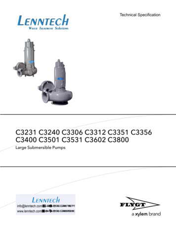
Technical SpecificationC3231 C3240 C3306 C3312 C3351 C3356C3400 C3501 C3531 C3602 C3800Large Submersible PumpsLenntechinfo@lenntech.com Tel. 31-152-610-900www.lenntech.com Fax. 31-152-616-289
Table of ContentsTable of Contents1 Product Description.21.1 Product overview. 21.2 Materials. 21.3 Mounting-related data. 51.4 Drive units. 62 Operational Data. 112.1 Application limits. 112.2 Motor data. 112.3 Monitoring systems: MAS 801 and MAS 711.112.3.1 Comparison of MAS 801 and MAS 711. 112.4 Monitoring with MAS 801. 132.4.1 System overview. 142.5 Monitoring with MAS 711. 15C3231 C3240 C3306 C3312 C3351 C3356 C3400 C3501 C3531 C3602 C3800 Technical Specification1
1 Product Description1 Product Description1.1 Product overviewSubmersible pump for pumping water and wastewater containing solids or soriesMechanical accessories which are available include the following: Cable handling systems Lifting equipmentElectrical accessories which are available include the following: Pump controller Control panels Starters MAS and other monitoring relaysSee your local sales and service representative for further information.OptionsThe following options are available: Zinc anodes for corrosion protection Special coating system (with epoxy base coat) for demanding environments Power monitoring Monitoring options for temperature, vibration and water in the oil housing1.2 MaterialsImpellerTable 1: C3240MaterialCast iron2Internal material numberM0314.0125.00StandardEuropeUSAEN 1561No. JL 1040ASTM-A 48– No 35 BC3231 C3240 C3306 C3312 C3351 C3356 C3400 C3501 C3531 C3602 C3800 Technical Specification
1 Product DescriptionMaterialDuplex stainless steelInternal material numberM0344.2324.12StandardEuropeUSAEN 10283No. 1.4474ASTM (CD-4MCuN)Table 2: C3231, C3306, C3312, C3356, C3400, C3501MaterialInternal material numberStandardEuropeUSACast ironM0314.0125.00EN 1561No. JL 1040ASTM-A 48– No 35 BDuplex stainless steelM0344.2324.12EN 10283No. 1.4474ASTM (CD-4MCuN)Internal material numberStandardTable 3: C3351, C3531MaterialEuropeUSACast ironM0314.0125.00EN 1561No. JL 1040ASTM-A 48– No 35 BCast iron: spheroidalgraphiteM0316.0727.02EN 1563No. JS 1050(GJS–500–7)ASTM-A 536– No. 80-55-06Duplex stainless steelM0344.2324.12EN 10283No. 1.4474ASTM (CD-4MCuN)Internal material numberStandardTable 4: C3602MaterialEuropeUSACast ironM0314.0125.00EN 1561No. JL 1040ASTM-A 48– No 35 BDuplex stainless steelM0344.2324.12EN 10283No. 1.4474ASTM (CD-4MCuN)Cast iron: spheroidalgraphiteOnly drive units 965, 975,985, 995.M0316.0727.02EN 1563No. JS 1050(GJS–500–7)ASTM-A 536– No. 80-55-06Internal material numberStandardTable 5: C3800MaterialEuropeUSACast iron: spheroidalgraphiteM0316.0727.02EN 1563No. JS 1050(GJS–500–7)ASTM-A 536– No. 80-55-06Duplex stainless steelM0344.2324.12EN 10283No. 1.4474ASTM (CD-4MCuN)C3231 C3240 C3306 C3312 C3351 C3356 C3400 C3501 C3531 C3602 C3800 Technical Specification3
1 Product DescriptionPump housingTable 6: C3231, C3240, C3306, C3312, C3351, C3356, C3400, C3501, C3531, C3800MaterialInternal material numberCast ironM0314.0125.00StandardEuropeUSAEN 1561No. JL 1040ASTM-A 48– No 35 BTable 7: C3602InstallationMaterialInternal materialnumberStandardEuropeUSACTCast iron: spheroidal M0316.0727.02graphiteEN 1563No. JS 1050(GJS–500–7)ASTM-A 536– No. 80-55-06OtherCast ironEN 1561No. JL 1040ASTM-A 48– No 35 BM0314.0125.00Mechanical face sealsThe inner seal is always corrosion resistant cemented tungsten carbide (WCCR). The outerseal can be either corrosion resistant cemented tungsten carbide (WCCR), or corrosionresistant silicon carbide (RSiC).SealMaterial, rotating ringMaterial, stationary ringInnerCorrosion resistant cementedtungsten carbide (WCCR)WCCROuterWCCRWCCRCorrosion resistant silicon carbide(RSiC)RSiCDrive unit shaftMaterialInternal material numberStandardEuropeUSAMartensitic stainless steelM0344.2321.03EN 10088-3No. 1.4057ASTM/AISI 431Duplex stainless steelM0344.2324.02EN 10088-3No. 1.4460ASTM/AISI 329MaterialInternal material numberStandardO-ringsNitrile rubber 70⁰ IRHM0516.2637.04EuropeUSA——Coating systemThe following table describes the two variants of paint systems available for the pump,Standard and Special. The choice of coating system depends upon the serviceenvironment.4Coating systemBasecoatTopcoatTotal dry film thicknessStandardAcrylic (waterborne)oralkyd (solventborne)Oxirane ester, 2–pack120–350 μmC3231 C3240 C3306 C3312 C3351 C3356 C3400 C3501 C3531 C3602 C3800 Technical Specification
1 Product DescriptionCoating systemBasecoatTopcoatTotal dry film thicknessSpecial (option)Epoxy, 2 layersOxirane ester, 2–pack, 1layer350–700 μmOther coating systems are available for special requirements such as drinking water, hightemperature, or erosion applications. See the Xylem internal standard M0700.00.0001(Coating Selection Guidelines).1.3 Mounting-related dataDepth of immersionThe maximum depth of immersion is 20 m (65 ft).WeightSee the dimensional drawing for pump weights.CablesTable 8: C3231, C3306, C3356SUBCAB Maximum voltage 600–1000 V, intended for drive units up to 1 kV. ConsultXylem for the cable dimensions.Table 9: C3240, C3312, C3351, C3400, C3501, C3531, C3602, C3800SUBCAB Maximum voltage 600–1000 V, intended for drive units up to 1 kV. ConsultXylem for the cable dimensions.NTSCGEWTOEUSFor use with medium voltage (1.2–6.6 kV) drive units. Consult Xylem for thecable dimensions.Engineering dataPerformance curves, motor data, and dimensional drawings are available from the localsales and service representative.Impeller throughletPumpThroughletmmInchC323188 / 1023.46 / 36021264.96C38001445.67C3231 C3240 C3306 C3312 C3351 C3356 C3400 C3501 C3531 C3602 C3800 Technical Specification5
1 Product Description1.4 Drive unitsC3231Voltage rangeStandard drive unitsExplosionproof drive unitsMaximum number of startsper hourUp to 1 7367461076677610Voltage rangeStandard drive unitsExplosionproof drive unitsMaximum number of startsper hourUp to 1 86287215882892108638731088389310Voltage rangeStandard drive unitsExplosionproof drive unitsMaximum number of startsper hourUp to 1 7367461076677610Voltage rangeStandard drive unitsExplosionproof drive unitsMaximum number of startsper hourUp to 1 kV705715157357451576577515Up to 1 kVUp to 1 kVC3240Up to 1 kV1.2–6.6 kV1.2–6.6 kVC3306Up to 1 kVUp to 1 kVC33126C3231 C3240 C3306 C3312 C3351 C3356 C3400 C3501 C3531 C3602 C3800 Technical Specification
1 Product DescriptionVoltage rangeStandard drive unitsExplosionproof drive unitsMaximum number of startsper hourUp to 1 8668761086287215882892108638731088389310Voltage rangeStandard drive unitsExplosionproof drive unitsMaximum number of startsper hourUp to 1 Voltage rangeStandard drive unitsExplosionproof drive unitsMaximum number of startsper hourUp to 1 7367461076677610Voltage rangeStandard drive unitsExplosionproof drive unitsMaximum number of startsper hourUp to 1 Up to 1 kVUp to 1 kV1.2–6.6 kV1.2–6.6 kVC33511.2–6.6 kVC3356Up to 1 kVUp to 1 kVC3400Up to 1 kVC3231 C3240 C3306 C3312 C3351 C3356 C3400 C3501 C3531 C3602 C3800 Technical Specification7
1 Product DescriptionVoltage rangeStandard drive unitsExplosionproof drive unitsMaximum number of startsper hourUp to 1 86287215882892108638731088389310Voltage rangeStandard drive unitsExplosionproof drive unitsMaximum number of startsper hourUp to 1 287215882892108638731088389310Voltage rangeStandard drive unitsExplosionproof drive unitsMaximum number of startsper hourUp to 1 805815158358451586587515Up to 1 kV1.2–6.6 kV1.2–6.6 kVC3501Up to 1 kVUp to 1 kVUp to 1 kV1.2–6.6 kV1.2–6.6 kVC3531Up to 1 kVUp to 1 kV8C3231 C3240 C3306 C3312 C3351 C3356 C3400 C3501 C3531 C3602 C3800 Technical Specification
1 Product DescriptionVoltage rangeStandard drive unitsExplosionproof drive unitsMaximum number of startsper hourUp to 1 899810Voltage rangeStandard drive unitsExplosionproof drive unitsMaximum number of startsper hourUp to 1 9810Voltage rangeStandard drive unitsExplosionproof drive unitsMaximum number of startsper hourUp to 1 kV905915109359451096597510Up to 1 kV1.2–6.6 kV1.2–6.6 kV1.2–6.6 kVC3602Up to 1 kVUp to 1 kVUp to 1 kVUp to 1 kV1.2–6.6 kV1.2–6.6 kV1.2–6.6 kVC3800C3231 C3240 C3306 C3312 C3351 C3356 C3400 C3501 C3531 C3602 C3800 Technical Specification9
1 Product Description10Voltage rangeStandard drive unitsExplosionproof drive unitsMaximum number of startsper hour1.2–6.6 kV950960109859951098899810C3231 C3240 C3306 C3312 C3351 C3356 C3400 C3501 C3531 C3602 C3800 Technical Specification
2 Operational Data2 Operational Data2.1 Application limitsTable 10: Process dataParameterValueLiquid temperatureMax. 40 C ( 105 F)Depth of immersionMax. 20 m (65 ft)pH of pumped liquidpH 5.5–14Liquid densityMax. 1100 kg/m3 (9.17 lb per gal.)2.2 Motor dataMotor characteristicsFeatureDescriptionFrequency50 Hz or 60 HzStator insulation classH (180 C [356 F])Voltage variationMax. /- 10%Voltage imbalance between the phases2%Motor encapsulationMotor encapsulation is in accordance with IP68.2.3 Monitoring systems: MAS 801 and MAS 711The pump is designed to be used with the following monitoring systems: MAS 801 MAS 7112.3.1 Comparison of MAS 801 and MAS 711Drive units up to 1 kVDescriptionMAS 801MAS 711Signal cableBuilt into the motorcable.Separate signal cable(1),with 12 or 24 leads, isneeded.PEMStandardN/APump current, 1 phaseStandardA current transformer inthe control cabinet isneeded.Pump current, 3 phaseA current transformer in A current transformer inthe control cabinet is the control cabinet isneeded.needed.Optional. Separate electronic instrument withthree current transformers.Power monitoringPAN 312Vibration in three directionsBuilt into PEMStandardN/AVibration in one directionVIS 10N/AOptional (2)Leakage in the junction boxFloat switch leakagesensor, FLSStandardStandardC3231 C3240 C3306 C3312 C3351 C3356 C3400 C3501 C3531 C3602 C3800 Technical Specification11
2 Operational DataDescriptionStator winding temperature in onephaseStator winding temperatureThermal contacts or PTC thermistorsMAS 801MAS 711Pt100 analog temperaturesensor in one statorStandardwindingStandardThermal contacts (3)StandardStandardPTC thermistors (3)OptionalOptionalStator winding temperature inphases 2 and 3Pt100 analog temperaturesensors in two more stator OptionalwindingsOptional (2)Main bearing temperaturePt100 analog temperatureStandardsensorStandardLeakage in the stator housing orinspection chamberFloat switch leakagesensor (FLS)StandardWater in oil: Not applicable for EXdrive units, or drive units withinternal closed-loop cooling.Capacitive leakage sensorOptional(CLS)Optional (2)Support bearing temperaturePt100 analog temperatureOptionalsensorOptional (2)Pump memoryStandardIncluded in PEMStandardDescriptionMAS 801MAS 711Signal cableBuilt into the motorcable.Separate signal cable(1),with 24 leads, isneeded.PEMStandardN/APump current, 1 phaseStandardA current transformer inthe control cabinet isneeded.Pump current, 3 phaseA current transformer in A current transformer inthe control cabinet is the control cabinet isneeded.needed.(1) Also known as auxiliary, control, or pilot cable.(2) The signal cable must have 24 leads.Drive units 1.2–6.6 kV12Optional. Separate electronic instrument withthree current transformers.Power monitoringPAN 312Vibration in three directionsBuilt into PEMStandardN/AVibration in one directionVIS 10N/AOptionalLeakage in the junction boxFloat switch leakagesensor (FLS)StandardStandardStator winding temperaturePTC thermistors: 3 3 (3)StandardStandardStator winding temperature inphases 1, 2 and 3Pt100 analog temperaturesensors in each statorStandardwinding: 3 3 (3)StandardMain bearing temperaturePt100 analog temperatureStandardsensorStandardLeakage in the stator housingFloat switch leakagesensor (FLS)StandardStandardWater in oil: Not applicable for EXdrive units, or drive units withinternal closed-loop cooling.Capacitive leakage sensorOptional(CLS)OptionalC3231 C3240 C3306 C3312 C3351 C3356 C3400 C3501 C3531 C3602 C3800 Technical Specification
2 Operational DataDescriptionSupport bearing temperatureMAS 801MAS 711Pt100 analog temperatureOptionalsensorOptionalPump memoryIncluded in PEMStandard(1) Also known as auxiliary, control, or pilot cable.(3) 6 total: 3 sensors are connected and 3 are built-in spares.Stator winding temperatureMAS 801 and MAS 711 offer the same monitoring configurations for stator windingtemperature. They are shown in the following table.Table 11: Stator winding temperature, monitoring configurationsDrive unitsSensors in coil ends of statorwindingsAdditional sensors, which are incorporated in the statorwindings:Always presentUp to 1 kVOne of the following choices: Standard: Pt100 analoguetemperature sensor in 1 stator Standard: 3 thermalwindingcontacts Optional: 3 PTC thermistors1.2–6.6 kVPTC thermistors (3 3)3 sensors are connected inseries, and 3 are built-inreserves.Extra optionOptional: Pt100 analoguetemperature sensors in 2 morestator windingsPt100 analogue temperaturesensors in all 3 stator windings(3 3)Each winding has 1 sensor thatis connected, and one sensorthat is a built-in reserve.2.4 Monitoring with MAS 801Pumps with the standard MAS 801 equipment are mounted with the following items: Thermal contacts or PTC thermistors for stator winding temperature monitoring (3 inseries) Leakage sensor in the stator housing Leakage sensor in the junction box Pt100 sensor for main bearing temperature monitoring Pt100 sensor for stator winding temperature in one phase Vibration in three directions Current transformer for pump current and frequency measurementThe following options are possible with MAS 801: Pt100 sensors for stator winding temperature measurement in phases 2 and 3 Pt100 sensor for support bearing temperature measurement Leakage sensor in the oil housing (CLS)Optional monitoring channels by using power analyzer PAN 312 Three-phase powerPower factorSystem voltageVoltage imbalancePump currentCurrent imbalanceC3231 C3240 C3306 C3312 C3351 C3356 C3400 C3501 C3531 C3602 C3800 Technical Specification13
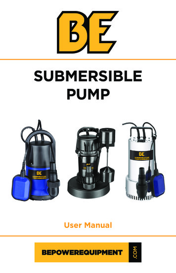
2 Operational Data2.4.1 System overviewThe MAS 801 is a monitoring system that protects the pumps, by using measurementsfrom pump sensors and measurement modules. The system offers considerablefunctionality for the benefit of different user categories: A graphical user interface, the configuration and analysis tool, for computer and HMI Local and remote presentation of pump status, key data, and alarms Analysis and troubleshooting that is based on graph functions, alarm lists, and blackboxes Service reminders and reporting Configuration of the system and monitoring channels Protocols for communication with external automation electronics, SCADA, and cloudapplicationsThe system consists of a central unit a base unit, a pump electronic module, and an HMI.9471286286286533WS010854A3Table 12: Parts14NumberPartProduct nameDescription1Central unit(CU)MAS CU 801The central unit communicates with all base units in thesystem, up the maximum ten base units. The central unitincludes the configuration and analysis tool, embeddedwebpages, that is used to interact in the system. The centralunit is typically installed in an electrical cabinet.2Base unit(BU)MAS BU 811The base unit communicates data between the pumpelectronic module and the central unit. If needed, for pumpprotection, the base unit stops the pump. The base unit istypically installed in an electrical cabinet.3Pump electronicmodule(PEM)MAS PEM 811The pump electronic module communicates with the baseunit and contains factory settings, specific to the individualpump. It is connected to the pump sensors and storesmeasured data. The pump electronic module is mounted inthe pump junction box.C3231 C3240 C3306 C3312 C3351 C3356 C3400 C3501 C3531 C3602 C3800 Technical Specification
2 Operational DataNumberPartProduct nameDescription4Human-machineinterface (HMI)FOP 402The HMI is connected to the central unit and displays theconfiguration and analysis tool, for user interaction. TheHMI is typically front-mounted in an electrical cabinet door.5Computer-A computer can be connected to the central unit locally orremotely, and displays the configuration and analysis tool,for user interaction.6Two-wirecommunication-Bus communication between the pump electronic moduleand the base unit in a SUBCAB cable. The buscommunication is tolerant to electromagnetic interference.7DeviceNet-Communication bus connecting the central unit with baseunits.8Power analyzer,optionalPAN 312Measures power, power factor, current in three phases,voltage in three phases, voltage imbalance, energy9ControllerSCADA system-Not part of the MAS 801 system. MAS 801 uses openprotocol for communication with external controller orSCADA systems.CommunicationMeasurements and pump information are transmitted over the two wires from each pumpelectronic module. The data goes through the base unit and further on to the central unitover the DeviceNet bus. This way two equal databases (CU and PEM) of pump informationare continually updated securing redundancy and providing different access possibilities.2.5 Monitoring with MAS 711With the Flygt MAS 711 monitoring system, the parameters that are tracked can includethe following: Temperature: main and support bearings, stator windings Vibration Leakage: in stator housing, junction box, and water into oil chamber Power monitoringTable 13: Parameters monitoredDescriptionSensorStandard or optionalPump memoryPrinted circuit board for pump memory includesa temperature sensor.StandardLeakage in the junction boxFloat switch leakage sensor, FLSStandardMain bearing temperaturePt100 analogue temperature sensorStandardLeakage in the stator housing orinspection chamberFloat switch leakage sensor, FLSStandardStator winding temperatureSee the following table.StandardSupport bearing temperaturePt100 analogue temperature sensorOptionalWater in oilNot applicable for drive units withinternal closed-loop coolingCapacitive leakage sensor (CLS)OptionalVibrationVIS 10OptionalPower monitoringSeparate electronic instrument which uses threecurrent transformers.OptionalPump currentA current transformer in the control cabinet is required.C3231 C3240 C3306 C3312 C3351 C3356 C3400 C3501 C3531 C3602 C3800 Technical Specification15
Xylem ’zīləm 1) The tissue in plants that brings water upward from the roots;2) a leading global water technology company.We’re a global team unified in a common purpose: creating advancedtechnology solutions to the world’s water challenges. Developing newtechnologies that will improve the way water is used, conserved, and re-used inthe future is central to our work. Our products and services move, treat, analyze,monitor and return water to the environment, in public utility, industrial,residential and commercial building services, and agricultural settings. With itsOctober 2016 acquisition of Sensus, Xylem added smart metering, networktechnologies and advanced data analytics for water, gas and electric utilities toits portfolio of solutions. In more than 150 countries, we have strong, longstanding relationships with customers who know us for our powerfulcombination of leading product brands and applications expertise with a strongfocus on developing comprehensive, sustainable solutions.Lenntechinfo@lenntech.com Tel. 31-152-610-900www.lenntech.com Fax. 31-152-616-289Visit our Web site for the latest version of this documentand more informationThe original instruction is in English. All non-Englishinstructions are translations of the original instruction. 2013 Xylem Inc884283 5.0 en-US 2018-05 TS C3231 C3240 C3306 C3312 C3351 C3356 C3400 C3501 C3531 C3602C3800
Large Submersible Pumps info@lenntech.com Tel. 31-152-610-900 www.lenntech.com Fax. 31-152-616-289 . Submersible pump for pumping water and wastewater containing solids or long-fibred material. Installations Pump Installation P S T Z C3231 X X X X C3240 X X X X C3306 X X X X