Transcription
HYDRAULIC PUMP DRIVESMobile equipment hydraulic pump drives engineered for theconstruction, forestry, petroleum, marine and agricultural markets.
Gear Products is a leading manufacturer of mechanical power transmission components foroff-highway trucks, cranes and heavy equipment that serve the utility, petroleum, construction,agricultural, forestry, marine and mining industries. We distinguish ourselves by delivering customengineered products quickly — with the superior quality and long-lasting performance our customershave come to expect since 1957.Gear Products offers one of the largest product ranges of its kind anywhere. Our planetary and wormgear winches, swing drives, auger drives, slewing ring bearings, rotators, gearboxes, and modularhydraulic pump drives are renowned for reliable operation and long-lasting performance, even underthe toughest conditions. With the widest selection of gearboxes in the industry, Gear Productsmanufactures both single and multi-pump drives, giving our OEM customers added design flexibility tomeet the needs of their customers.No matter how complex the requirements or application, Gear Products is dedicated to productexcellence. Our attention to detail and customer responsiveness are quite simply unmatched. Youmight say the backbone of our success is a combination of the finest in man and machine— advancedtechnology, precision manufacturing, and a team of committed professionals all working in concert tokeep world industry moving.Now, as a part of TWG, Gear Products enters a new era of product excellence by expanding thebreadth and depth of our product lines and making our components more available to dealer networksthroughout the western hemisphere. With the strength, support and added capabilities we now enjoy,Gear Products is positioned to become an even greater force in engineering innovation.Welcome to the next generation of Gear Products.11135 S James AveJenks OK 74037-1731 USAvoice: 1-918-298-8300fax: 1-918-298-8301email: salesinfo@dovertwg.comwww.dovertwg.com
www.dovertwg.comCaution .2Thermal Capacity.2HPD Engine Mounting Recommendations.3Model Code.4Application & Installation Information.5TABLE OF CONTENTSImportant Notice.2Single Pump Models.6Double Pump Models. 14Triple Pump Models.22Four Pump Models.30Five Pump Models.34In-Line Four & Five Pump Models.36Six Pump Models.38Eight Pump Models.38Power Take-off Adapter.40Engine Flywheel Housing Data.41Mounting Flanges & Shaft Specifications.43Remote Control of Over Center Clutch.44Output Location Sequence.45Limited Warranty.45Lubrication Information.46Fluid Power Formulas.47TWG Gear Products 11135 S James Ave, Jenks OK 74037-1731, USA 1-918-298-8300 www.dovertwg.com1
IMPORTANT NOTICEDisregarding system torsional compatibility can cause damage to components in the drive train, resultingin a loss of mobility for which the hydraulic pump drive is intended. At a minimum, system torsionalincompatibility will result in undesirable noise and vibration at low speeds.Gear Products, Inc. (GPI) recommends that a torsional vibration analysis of the pump drive/drive trainsystem be performed on all new installations. Torsional vibration analysis can be made by the enginebuilder or by an independent consultant.CAUTION!Any user of enclosed gear drives should make certain they have the latest available data on the factorsaffecting the selection of a gear drive. When better load intensity information is available on drive or drivenequipment, this should be considered when an application factor is selected. Reference AGMA 6010-F97ANNEX A.The factors to be considered are:1. The driven equipment (cranes, blowers, etc.)2. The type of drive (turbines, gas or diesel engines)3. Load duration (duty cycle)4. A duty cycle should be submitted with your application dataTHERMAL CAPACITYGear Products strongly recommends that the gearbox be monitored for at least one hour after installationfor noise levels and to assure no overheating occurs. When using SAE 90 wt. oil, the maximum allowablegear housing temperature is 220 degrees F (104 degrees C). It is suggested that the unit be monitored atnormal operating conditions.There are many factors that affect the thermal temperature ranging from ambient air and air flow, differentialor adjoining member temperatures and cleanliness of the housing. Ratings may also be limited by theclutch ratings, line drives or pumps.If overheating conditions occur, provisions should be considered for additional cool ing. Contact GearProducts for recommendations.2TWG Gear Products 11135 S James Ave, Jenks OK 74037-1731, USA 1-918-298-8300 www.dovertwg.com
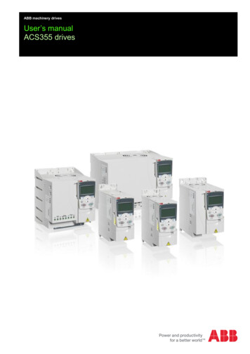
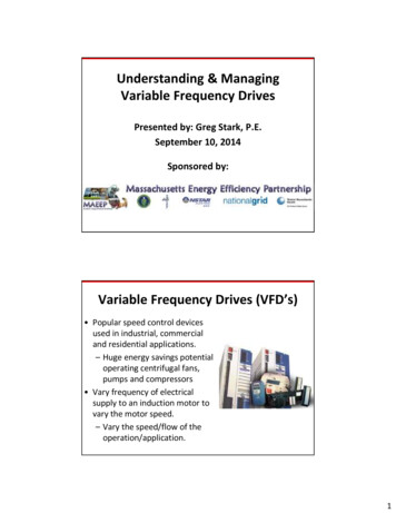
www.dovertwg.comHYDRAULIC PUMP DRIVE ENGINE MOUNTING RECOMMENDATIONS1. Obtain from the engine manufacturer a torsionalvibration and bending fatigue analysis. Torsionalvibration on the HPD will be furnished by GPI uponrequest.2. A three (3) point elastomer isolator mount is recom mended to prevent the engine and HPD frombecoming a structural member of the equipment.For isolator selection and load analysis consult theisolator manufac turer.3. Contact your engine manu facturer for flywheelhousing bending moment data. A saddle mountbracket de signed to accomodate the bendingmoment of the HPD package is suggested.Ref: Cummins Bul. 3382362. “Construction,Mining, Logging and Agricultural InstallationRecommendation for Engine Mounting” (ref. fig.5: determination of bending moment for saddlebracket transmis sion support).4. A one piece support bracket tying the HPD to theengine flywheel housing is recom mended. Thesupport bracket should be fabricated from 1/2” min.thick cold rolled plate, welded, stress relieved andmachined. The support bracket bolt hole patternshould be established from approved drawingsobtained from the engine manufacturer and GPI.The bolt hole diameters should not be greater thanthe attaching bolt diameter plus 1/32”. The supportbracket surfaces that mate to the flywheel housingand to the HPD housing must be milled flat andparallel.5. The location of rear support isolators (R2) shouldbe determined by calculation to produce a zerobending moment when the wet weight of the HPDand the hydraulic pumps are installed on theengine.6. Please note, this type of installation procedure doesnot take into consideration dynamic shock loads orforces caused by very short hose lengths, etc.TWG Gear Products 11135 S James Ave, Jenks OK 74037-1731, USA 1-918-298-8300 www.dovertwg.com3
MODEL CODE FOR HYDRAULIC PUMP DRIVESDSPC5328 p DataA2 SAE “A”, 2 BoltB SAE “B”, 2 or 4 BoltBB SAE “BB”, 2 or 4 BoltC SAE “C”, 2 or 4 BoltCC SAE “CC”, 2 or 4 BoltD4 SAE “D”, 2 or 4 BoltE4 SAE “E”, 4 BoltInputC - ClutchG - GearP - PlateR - Rubber BlockS - ShaftT - TorsionalCouplingGear RatioE EvenD DownU UpOutput0 1 Pump, Direct1 1 Pump, Geared2 2 Pump, Geared3 3 Pump, Geared4 4 Pump, Geared5 5 Pump, GearedRefer to selected models foravailable gear ratiosDrive Plate/Clutch Nominal Size(per SAE J620) forPlate DiameterSAE HousingClutch Model6 6.5 in.2 or 3C1107 7.5 in.2 or 3C1118 8 in.2 or 3P11110 10 in.0 or 1P21111 11.5 in.0 or 1P11414 14 in.0 or 1P21418 18 in.P314Gear Center Distance01 Non Geared5 5.429 in.6 6.0 in.7 7.0 in.8 8.0 in.9 9.0 in.1 or 0 10.5 in.Engine Adapter Housing0 SAE “0”1 SAE “1”2 SAE “2”3 SAE “3”4 SAE “4”5 SAE “5”Shaft DriveSF FLANGESK KEYEDRK EXTERNAL KEY29T NO. SPLINE TEETHNot all combinations can be built. Check with GPI Engineering for your requirements.4TWG Gear Products 11135 S James Ave, Jenks OK 74037-1731, USA 1-918-298-8300 www.dovertwg.com
www.dovertwg.comAPPLICATION & INSTALLATION INFORMATIONCompany NameAddressData Supplied ByTitleDateData Received ByTitleDateAnnual Production Requiring HPDsPrototype RequiredYesType of EquipmentIndustrialStart-Up DateNoNumberMarineEngine Type and ManufacturerModel No.HPD LocationRequired DateMobileElectric MotorHorsepowerFrontOther@ Full Load Gov. rpmRearRemoteSAE Flywheel Housing Size (J620C)SAE Flywheel Size (SAE J617)Flywheel Offset (“G” Dimension SAE J617)Pilot Bearing SizeClutch SizeHPD Input DrivePlate SizeShaft TypeRubber Block SizeGear RatioLocationASAE MountModelPump MakeShaftBSAE MountModelPump MakeShaftCSAE MountModelPump MakeShaftDSAE MountModelPump MakeShaftESAE MountModelPump MakeShaftTWG Gear Products 11135 S James Ave, Jenks OK 74037-1731, USA 1-918-298-8300 www.dovertwg.com5
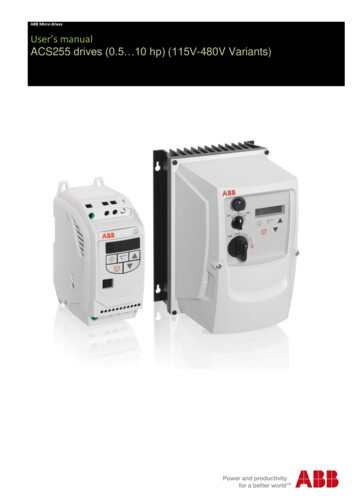
DP01 SERIESSPECIFICATIONSDRIVE PLATE DIMENSIONSREF SAE J620Ratings may vary depending on duty cycle load andenvironment. Refer to SAE J744c informa tion onpage 43 or contact your pump supplier.Gear Products Single Pump Direct Drives areavailable in three configurations.NOMINAL DRIVEPLATE DIA.BBCCEFG6 1/28.5007.8755/1661.187 .627/1682.1211 50021.3711/166.62Specifications are subject to change without notice.FEATURESPUMP FLANGE DIMENSIONS Drive Plate Pilots off O.D. of Flywheel Instead of PilotBore Hubs are Secured to the Flex Plate with Lock titedCapscrews Rather than Cold Rivets Heavy Duty Drive PlateSTANDARD DP01Our standard model DP01, is available in a wide selection,0-5 housings and A through F pump size.ENGINE ADAPTER DIMENSIONSREF SAE 05025.50028.0026.759/1616*16030 DEG.INVOLUTESPLINEREF SAE .87138/16F47.0001-813.781.06158/16DP01 ZERO OFFSETFor tight fits GPI can put the pump face on the same plane as the bell housing face saving you as much as three inches over some competitors.Available in #3 housings, 10 or 11.5 inch flywheels and “C” pump adatation. Other sizes are available upon request.ENGINE ADAPTER DIMENSIONSDRIVE PLATE/CLUTCH DRIVE RINGREF SAE OMINALCLUTCHAND DRIVEPLATEDIAMETERBBCCEFG1012.37511.627/1682.1211 1/213.87513.127/1681.56DP01 -5/8 NESTED OFFSETModel DP01 (-5/8) allows the pump to be nested 5/8 inches inside the bell housing. this is very important when stacking pumps or in a cinfinedengine compartment. Currently available in #3 housings, either 10 or 11.5 inch flywheel and B, BB, C and CC pump adatation. Other sizes areavailable upon request.ENGINE ADAPTER DIMENSIONSDRIVE PLATE/CLUTCH DRIVE RINGREF SAE 875NOMINALCLUTCHAND DRIVEPLATEDIAMETERBBCCEFG1012.37511.627/1681.5611 1/213.87513.127/1681.56TWG Gear Products 11135 S James Ave, Jenks OK 74037-1731, USA 1-918-298-8300 www.dovertwg.com
www.dovertwg.comSINGLE DIRECT PLATE DRIVESTWG Gear Products 11135 S James Ave, Jenks OK 74037-1731, USA 1-918-298-8300 www.dovertwg.com7
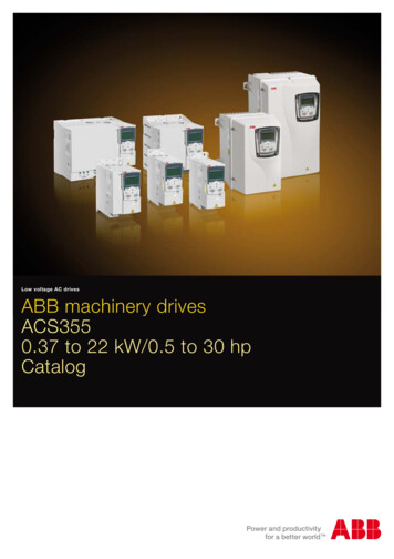
MODEL DC01SPECIFICATIONSPUMP FLANGE DIMENSIONSInput Torque: Clutch DependentInput Speed: Clutch DependentSpecifications are subject to change without notice.30 DEG.INVOLUTESPLINE*ADAPTERWIDTHREF SAE IA.(Y)HOLEDEPT(EE)(Z)DIST 3.781.061.06158/161 15/32CLUTCH HOUSING DIMENSIONSFEATURESREF SAE J620 AND SAE J617 Engine Wise RotationMODEL DC01 FOR P111AND LARGER CLUTCHESSAE 6025.50028.0026.759/161611.371/2CLUTCH INSTALLATION ORQUE (LB-IN)ON OPERATING SHAFTREQ’D TO ENGAGECLUTCHUUNITWT.(LBS)2 or 3P111285045513.87513.127/160.881.562.8351515.3833 3/1615401752 or 3P211285091013.87513.127/161.881.562.8351515.383 3/44 3/1619301850 or 1P114240081018.37517.259/160.501.003.1501823.384 1/26 3/831503050 or 1P2142500162018.37517.2
Gear Ratio Location A SAE Mount Pump Make ModelShaft B SAE Mount Pump Make ModelShaft C SAE Mount Pump Make ModelShaft D SAE Mount Pump Make ModelShaft E SAE Mount Pump Make ModelShaft . 6 oducts 11135 S ames Ave ens OK 403-131 USA 1-18-28-8300 .dovertwg.com DP01 ZERO OFFSET DP01 -5/8 NESTED OFFSET PUMP FLANGE DIMENSIONS REF SAE J744 30 DEG.