Transcription
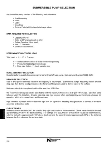
SUBMERSIBLE PUMP selectionA submersible pump consists of the following basic elements: Bowl Assembly Motor Cable Drop Pipe Surface Plate (with)(without) discharge elbowDATA REQUIRED FOR SELECTION Capacity in GPM Static and Pumping Levels in Well Setting Required (drop pipe) Well I.D. Diameter Electric CharacteristicsDETERMINATION OF TOTAL HEADTotal head H P F where:H Distance from surface to water level when pumpingP Pressure (head) at pump dischargeF Drop pipe friction ( ) check valve(s) lossBOWL ASSEMBLY SELECTIONSelect impeller in exactly the same manner as for lineshaft type pump. Note comments under WELL SIZE.DROP PIPE SELECTIONSize of drop pipe is selected based on the capacity to be pumped. Submersible pumps frequently require smallerdrop pipe than do line shaft pumps since the full area of the pipe is used to deliver water to the surface.Minimum velocity in drop pipe should not be less than 3.5Ft./Sec.We recommend drop pipe size be selected to limit the maximum friction loss to 5’ per 100’ of pipe. Selection tableis based upon this limitation. Smaller size drop pipe may be used when bowl assembly and motor are adequate foroperation with the increased head and horsepower.Pipe furnished by others must be standard pipe with 3/4 taper NPT threading throughout and to connect to the bowlassembly and surface plate.SUBMERSIBLESCHECK VALVESWhere total head exceeds 200’, the use of a drop pipe check valve is recommended. Check valve should be locatedapproximately 20’ above the bowl assembly. For settings over 600’, the use of two check valves are recommended,with the first valve approximately 100’ above bowl unit and the second located approximately 60% of the distancebetween the first valve and the surface plate.260A GORMAN-RUPP COMPANY
SUBMERSIBLE PUMP selection (cont.)CABLE SELECTIONSelect a drop cable designed for use in water. The insulation on the conductors should be RW, RUW, TW, or theirequivalent. DO NOT compromise on drop cable quality. Paying a little more will save you money in the long run.Cable selection chart is based on horsepower, voltage, and length of cable required. Cable sizes and lengths aremaximum allowable. Higher operating efficiency will be obtained by using the next larger cable size when lengthsapproach listed limits. All size and cable lengths shown are for copper wire only.NOTE: Use of smaller cable than recommended will void warranty.Select cable length equal to length of setting plus an additional 10’ or more to connect to starter at the surface, plus 1additional foot for each 50’ of length in the well to compensate for unavoidable slack in the installation.SURFACE PLATESurface place consists of flat steel plate with connection for drop pipe, hole for entrance of cable, vent hole, hole forair line or water level gauge. Surface plate is supplied (with)(without) elbow. If elbow is furnished, it can be flangedor female thread. Surface plate is selected to match drop pipe size.MOTOR SELECTIONMotor selection is based upon horsepower required, pump RPM, thrust load, well diameter, and power supply. Also,see comments under WELL SIZE and WATER TEMPERATURE.STARTING EQUIPMENTSelecting the proper overload protection is one of the most important factors in obtaining a successful submersibleinstallation. Submersible motor starters should provide the following: Positive motor protection against single phasing. Positive motor protection against sustained overload in excess of 115% of motor rating. Motor protection if rotor is stalled. Tripping timers independent of ambient temperature; (Ambient Compensated Quick Trip Heaters).NOTE: Failure to provide quick trip overload heaters will void warranty.Also, note that under certain conditions of maximum load on the motor (use of the 1.15 service factor), a starter onesize larger may be required.LIGHTNING PROTECTIONLightning and power surge damage are major causes of submersible motor failures, so a three-phase lightningarrestor is a must. The arrestor is mounted in the pump panel and grounded to both ground terminals onto pumppanel and well head. If you use plastic pipe, the ground wire should also be connected to a stud on the motor to obtaingood grounding and maximum benefit from the arrestor.A GORMAN-RUPP COMPANY261SUBMERSIBLESWARNING: Failure to ground this unit may result in serious electrical shock. A faulty motor or wiring can be aserious electrical shock hazard if it is accessible to human contact. To avoid this danger, connect themotor frame to the power supply grounding terminal with copper conductor no smaller than the circuitconductors. In all installations, connect above ground metal plumbing to the power supply ground perNational Article 250-80 to prevent shock hazard.
Selection procedure exampleRequirements:Capacity.850 GPMHead.140 FeetPumping Level.200 FeetWell Diameter.12” Inside DiameterPower Supply.3 Ph. / 60 Hertz / 480 VoltsPumping Liquid.Fresh Water1. Determine Total Dynamic Head: (TDH) pumping level head required drop pipe friction loss checkvalve(s) frictionTDH a. Pumping level.200 Feetb. Head required.140 Feetc . 8” drop pipe friction head for 850 GPM is 2.2 feet per 100 feet.200 feet of new 8” drop pipe has a total loss of 2.2 x 2.0 .4.4 Feetd. Friction head loss in one 8” check valve .2.2 FeetTOTAL Dynamic Head (TDH). 346.6 Feet2. Impeller Selection:Since no speed was specified, use 3450 RPM. The S9XHC shows 76% efficiency, full diameter.a. Number of stages required TDH 346.6 2.78 USE 3 stages, 75.5%No. Stg. Head/Stage125b. Total Pump Thrust TDH x Impeller Thrust Factor x Sp. Gr. (Rotor weight per stage x number of stages)(349.55 x 4.9 x 1) (10.6 x 3) 1744.6c. Bowl Horsepower GPM x TDH x Sp. Gr. 850 x 346.6 x 1 98.54 BHP3960 x Bowl Eff.3960 x 75.5%d. Pump Efficiency GPM x TDH x Sp. Gr. 850 x 346.6 x 1 75.5%3960 x Bowl H.P.3960 x 98.54SUBMERSIBLES262A GORMAN-RUPP COMPANY
Selection procedure example (cont.)3. Motor Selection:a. Bowl Horsepower 98.54b. Pump Operating Speed 3450 RPMc. Total Pump Thrust 1744.6d. 3 Phase, 60 Hertz, 460 Volts (nameplate)e. Thrust Bearing Loss .10 x Total Pump Thrust .10 x 1744.6 .17 H.P.10001000f. Horsepower Loss in Cable:Total Cable Length 200 feet 10 4 214 feetSelect #00 cable from Selection Chart100 H.P. motor current 130 amps full loadHorsepower loss in #00 cable H.P. loss per 100’ x Total Cable Length .65 x 214 1.39HP100100g. Total Horsepower: Bowl horsepower Thrust HP loss Cable horsepower loss 98.54 1.39 .17 100.10 H.P. (100 H.P. motor OK to use.)4. Cable Selection:a. Determine total cable length.Total Cable Length Pumping Level Surface Length Slack 200 10 4 214 feetb. Per Cable Selection Chart @ 460 volts horsepower, use #00 cable.5. Surface Plate:Use 8” surface plate.6. Check Valve:One 8” check valve required.7. Calculation of Field Performance:To determine field head and overall pump efficiency:a. Field Head laboratory head minus total friction loss.(1)Total friction loss loss in drop pipe check valve(s)b. Overall Pump Efficiency Water HP x (motor eff. % - cable loss %)Laboratory H.P.c. Water Horsepower GPM x Head3960d. Laboratory Horsepower GPM x Head x Sp. Gr.3960 x Pump Eff.Calculations for other values of power consumption can be carried out per equations noted below:A GORMAN-RUPP COMPANYSUBMERSIBLESe. Wire to Water Efficiency - same as Overall Efficiency.f. Input Horsepower Pump Brake HorsepowerMotor Efficiency - Cable Lossg. Wire to Water Horsepower Same as Input Horsepowerh. Kilowatt Hours per 100 Gallons Field head x .00314Overall Efficiencyi. Kilowatts Input Input Horsepower x 0.746j. Gallons per Kilowatt Hour Overall Efficiency x 1000Field Head x .00314263
DETERMINATION OF FIELD PERFORMANCEgeneral instructions1. Select drop pipe size from selection chart.(NOTE: 5’ per 100’ friction loss is maximum; 3.5’/Sec. velocity is minimum.)a. Calculate drop pipe friction lossFriction per 100 feet x drop pipe length check valve friction loss100b. Calculate Total Dynamic Head (TDH)TDH Pumping level discharge head required at surface check valve friction loss drop pipe friction loss2. Impeller Selection: From performance curves with known capacity and speed, select the bowl assembly that hasits peak efficiency as close as possible to desired capacity. Well I.D. must be larger than bowl diameter. If speedis unknown, the speed should be as high as possible for a given capacity.TDH Number of stagesa. Number of stages required Head/stageb. Total Pump Thrust (TDH x Impeller Thrust Factor x Sp. Gr.) (rotor weight per stage x number of stages)c. Bowl Horsepower GPM x TDH x Sp. Gr.3960 x Bowl Eff.d. Pump Efficiency GPM x TDH x Sp. Gr.3960 x Bowl H.P.SUBMERSIBLES264A GORMAN-RUPP COMPANY
DETERMINATION OF FIELD PERFORMANCE (cont.)3. Motor Selection:Select the proper electric motor from the following:a. Bowl Horsepowerb. Pump Operating Speedc. Total Pump Thrustd. Electric Power Supply Availablee. Thrust Bearing Loss in H.P.Horsepower loss per 1000# thrust (given by manufacturer is approx. .09 per 1000# thrust; use .10 H.P. per1000#) .10 x total pump thrust #1000#f. Horsepower loss in cable (from Cable Loss Chart) to determine horsepower loss per 100 feet.Total horsepower loss in cable horsepower loss per 100’ x Total Cable Length100NOTE: Total cable length pumping level distance from well at surface to starter panel allowancefor slack.g. Total Horsepower:Total H.P. bowl horsepower thrust horsepower loss cable horsepower loss4. Cable Selection:a. Determine total cable length.Total cable length pumping level surface distance to starter panel allowance for slackNOTE:(1)Slack cable, allow 2 feet per 100 feet(2)10 foot minimum for surface cable to starterb. From cable selection chart under proper voltage, select cable under motor full load amps for length of cableused.NOTE:If full load amps fall between amps on chart, go to next larger size.5. Surface Plate: Select the same size as drop pipe diameter.6. Check Valve: Select the same size as drop pipe diameter (if required by Technical Data).7. Accessories:a.b.c.d.e.Pump PanelAir Line and GaugeBanding ToolsBanding SuppliesCableSUBMERSIBLESA GORMAN-RUPP COMPANY265
b. Pump Operating Speed 3450 RPM c. Total Pump Thrust 1744.6 d. 3 Phase, 60 Hertz, 460 Volts (nameplate) e. Thrust Bearing Loss .10 x Total Pump Thrust .10 x 1744.6 .17 H.P. 1000 1000 f. Horsepower Loss in Cable: Total Cable Length 200 feet 10 4 214 feet Select #00 cable from Selection Chart