Transcription
INSTRUCTION MANUALSUBMERSIBLE PUMPSDat:12.07.00No:94-BA 5079E/ 1cFile:Q TAU ETABLE OF CONTENTSPart .1.42.9.1.5UseIntroductionType code explanationInstallationInstallation of pump guide systemPreparatory checksFlushing water connectionDirection of rotationLowering the pump into the sumpStart-upElectrical connectionPanel controlsOperator safetyMinimum requirementsRecommended additional controlsConnection tabulationLevel switchesLevel controlRequired submergenceMaintenanceOperating troublesMaintenance and serviceGeneralCooling typesField testsVisual checks after pulling pump unit from sumpMotor housing testOil checking on submersible motorsOil changeGreasing instructionsMotor cablesRe-connection of cableTest for leaksOverhaul chartAssembly / DisassemblyReplacement of mechanical sealRemoval of pump side mechanical sealMaintenance of motor side mechanical sealAssembly of back coverAssembly of pump side mechanical sealLeakage test for pump side mechanical sealTel. 0294-457712Fax 0294-457713
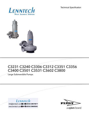
INSTRUCTION MANUALSUBMERSIBLE 4-BA 5079E/ 2cFile:Q TAU EEach pump unit is equipped with a nameplate attached to the motor, containing all motor and pump data(section 2.1.1). It is essential to give the complete data for any inquiry about parts or service.a)For pumps in normal operation (Fig. 1)Fig. 1b)Motors approved for hazardous locationaccording norm 94/9/EG (ATEX 100)- for online operation (Fig. 2).Fig. 2- for variable frequency driver (Fig. 3).These motors are equipped with triplethermistor according DIN - 44082 - S 150 CFig. 3The HIDROSTAL warranty is void unless the following requirements are met:1.Temperature protection circuit is wired so as to positively disconnect power to the motor whenexcessive winding temperature is sensed (Section 2.4.1.2f for wiring instructions).2.Proper extra-quick-trip overload protectors M U S T be used on all three phases of each motor(Section 2.4.1.2e).3.Optional conductivity probe circuit is wired to a special relay for use with these motors. See Section2.4.1.3g for wiring instructions and a list of approved relays.Tel. 0294-457712Fax 0294-457713
INSTRUCTION MANUALSUBMERSIBLE PUMPS12.07.0020.01.04Dat:4.No:94-BA 5079E/ 3eFile:Q TAU EAny repairs must be made exactly as per instructions in this manual, and using only genuineHIDROSTAL replacement parts furnished through the HIDROSTAL distribution organisation. Use ofany other parts will void the HIDROSTAL warranty.Prior to shipment, each pump has been tested by the factory for proper mechanical and electricaloperation as well as absolute water-tightness of the motor. Disassembly of the pump by other thanofficial HIDROSTAL service centers may cause loss of any remaining warranty.2.1.1TYPE CODE EXPLANATIONMOTOR CODEENYP6 - MNEQIdentification letter of the hydraulic size to which this motor can beassembled.The sizes are: B, C, D, E, F, H, I, L.Identification letter of the cooling type of this motor.N Submersible:cooled by direct transfer of heat fromsubmerged stator housing to surroundingambient liquid.Motor size, according IEC-norms:Line 2001 002 003 004 006 007 014 020030090 1303002/YType:B/Z3/X4/W5/VN6/U 7/TS100IEC:8090112 132 160 180 200 225 250 280 315 355Motor construction classificationMotor speedNominal speed50 Hz60 Hz23456789-2 pole motortwo speed, 2/4 poles4 pole motortwo speed, 4/6-poles6 pole motortwo speed, 6/8-poles8 pole motortwo speed, 8/10-polesTel. 900/720Fax 0294-457713
INSTRUCTION MANUALSUBMERSIBLE PUMPS12.07.0020.01.0494-BA 5079E/ 4hNo:File:Q TAU EMOTOR-CODE, continued:ENYP6-MNEQ1Pump side mechanical seal Pos. 515 typeC Fitted with Carbon-ceramic seal faces. Recommended for handling water,activated sludge and non-abrasive liquids.G Silicon carbide seal faces, rubber bellows with external spring.M Tungsten carbide - silicon carbide seal faces, rubber bellows with internalspring. For sludges, slurries and abrasive liquids.X Tungsten carbide - silicon carbide seal faces, stainless steel shell for higherpump pressures and/or higher motor speeds.Electrical classification:StandardEx-proofnewW/VB/ZN/U/T X/YNoldnewX/4/5***B Z Y X6/7**NNN without monitoring elementsX X X XSSS with internal moisture probe-IIIFF-with float switch-- Z ZZVVFwith internal moisture probeand float switch-- U UU---with bearing temperature probe---W*-WM*W*MotorsizeAdditional elementsLine 2001MotorsizeLine 2001Dat:construction with flywheelI-X-oldW/VXN/U/T 4/5XXY*--fitted additional elements are mentionned in the orderMotorsize 6 7: always with SA1-. (containing all above additional elements)Voltage of winding (see nameplate):A 230/460 V 60 HzE 400 V50 HzG 415 V50 HzK 575 V60 HzS special voltageQ Q-hydraulicK K-hydraulic1 or blank56 Material execution 1 Material execution 5 Material execution 6CABLE CODENAA1 - 10factory code (not important for instruction)length in metresTel. 0294-457712Fax 0294-457713
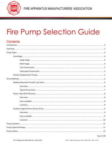
INSTRUCTION MANUALSUBMERSIBLE PUMPS30.06.0312.07.00Dat:2.2No:94-BA 5079E/ 5cFile:Q TAU EINSTALLATIONWET PIT PUMPSAll building and technical construction work must be finished before the pump will be installed. Make surethat length of cable supplied is sufficient for local conditions.Attention: very important: For installation and servicing it is recommended to install a block and tackleor chain hoist over the pump sump (or at least make sure that it could be installed later on). The liftingcapacity of the crane has to support at least double the weight of the pump. There should be a water supplyof about 4 bar (70 psi) pressure to wash down the pump when removed from the sump.Before installing any accessories or the pump ensure that the atmosphere is not potentially explosive.During the installation of the pump make sure that the free ends of the cables NEVER CONTACT WATER.2.2.1a)INSTALLATION OF PUMP GUIDE SYSTEM (Fig. 4)Fasten the upper guiderail bracket. Be sure toleave enough space for sliding shoe.b)Sump floor where the discharge stand is to beplaced must be even and level. Fasten thedischarge stand to the sump floor with cast-inplace or expansion-type bolts and nuts so thatthe guide rail pins or recesses on the dischargestand are vertically in line with (i.e. directlybelow) the guide rail pins on the bracket.c)The guide rails should be made from galvanizedstandard (or stainless steel) pipe. Cut pipe tothe correct length. Put lower pipe ends indischarge stand guiderail pins or recesses.Unbolt upper guide rail bracket. Insert pins intoupper pipe ends and re-bolt it. Check to see thatthe guide rails are exactly vertical and parallel.d)The discharge pipe must be connected withoutstress or misalignment to the discharge stand.upper guiderail bracketO-ringcable hookguide railsliding shoerubber sealIf a check valve is installed close to the pump,air must be vented from the pump casing ordischarge piping (before the check valve) duringfirst start-up to ensure priming (Section 2.2.3,Fig. 5).2.2.2PREPARATORY CHECKSchain hookdischarge standFig. 4Before lowering the pump into the sump check tosee that:- The lifting chain or steel lifting cable is correctly fastened to the lifting eyes.- The cable entry assemblies on motor have not been damaged or loosened and that the cables arefirmly gripped by the cable entry assemblies.- The cables have not been damaged during transportation or installation. Look especially for nicks andcuts on insulation; any damage penetrating through the outer layer of the cable will require replacementof them.- The cables are long enough and that they can follow the pump unhindered.Tel. 0294-457712Fax 0294-457713
INSTRUCTION MANUALSUBMERSIBLE PUMPS12.07.00Dat:-No:94-BA 5079E/ 6bFile:Q TAU EThe cable ends have never come in contact with water.The rubber seal on the pump discharge is correctly seated in its groove, and is not damaged.The rubber seal is throughly greased.The direction of rotation is correct (Section 2.2.4, Fig. 6).2.2.3FLUSHING WATER CONNECTIONPumps are supplied with a flushing water connection (serviceconnection "F", Fig. 5).For normal sewage application this connection is not used.However, in special cases when pumping high concentrationsof sludge or mud, it should be connected. It will conductcleaning water between impeller and pump side mechanicalseal (515), providing periodic removal of accumulated solids.Flushing water must be pressure-regulated between 0,5 to1 bar (7 to 14 psi) above pump discharge pressure. Water iscontrolled by a solenoid valve on a time clock. Adequateduration of each flushing is 60 seconds; frequently of flushingmust be established for each different installation.FThe quantity of flushing water varies according to pumpsizeand application: in most cases, flow rates of 6-8 litres perminute will be sufficient.Connection "F" may be used to manually bleed the air fromthe casing prior to start-up (Section 2.2.1d), if there is noother place for air to escape through the discharge piping.Fig. 52.2.4DIRECTION OF ROTATIONBefore lowering the pump into the sump, make electricalconnections as indicated in Section 2.4.2 and check thedirection of rotation. This must be counter-clockwise viewedfrom suction end. Check impeller rotation by suspendingpump from the lifting eyes, resting inclined on the floor, andstart up for one second. The starting jerk should becounter-clockwise viewed from driving side (Fig. 6).This procedure must be repeated for each speed, if unitsare multi-speed pumps.CAUTION:If rotation is not correct on multi-speed or multi-pumpinstallations, only change the pump cable leads of thepump or speed with wrong rotation at its starter in thecontrol panel. DO NOT change the primary power leadscoming into the control panel: This would change therotation of all pumps or speeds.direction ofstarting jerkdirection ofimpeller rotationcounter clockwiseviewed from suction endFig. 6Tel. 0294-457712Fax 0294-457713
INSTRUCTION MANUALSUBMERSIBLE PUMPSDat:30.06.0312.07.00No:94-BA 5079E/ 7dFile:Q TAU E2.2.5LOWERING THE PUMP INTO THE SUMP- Clear the sump bottom carefully of all building debris and other solid particles.- Lubricate the rubber seal with grease.- Lift and move the pump to a position directly over the guides until the sliding shoe fits correctly. Lower the pumpsteadily down to seat against the discharge stand. The sealing of mating faces is accomplished by the rubber sealthat is incorporated in the sliding shoe attached to the pump discharge flange. This is pressed to the dischargestand (after the pump is in position) by the pump's own weight.- When the chain is slack, unfasten the chain from the lifting device and fasten it to its retaining hook, so that thereis as little slack as possible.WARNING:The chain and cable must be fastened reliably to their retaining hooks. If they come loose they may be drawninto the pump suction with severe destructive consequences.2.3START-UPPrior to starting, check that:-level controls are correctly setoff-level is sufficiently high to prevent air entrance to the pump suctionsuction and discharge gate valves are completely openflood pump sumpthe pump may not be started if potentially explosive atmosphere is presentSTARTING OF PUMPNever start pump against closed valves (except non-return valves).Start the pump using manual operation. Measure the amperage drawn on each phase leg. Record and verify thesereadings with the nameplate ratings. If amperage is more than 5 % higher, stop pump and check probable causesaccording to "Operating Troubles" chart (Section 2.5.1).Once preliminary checks are complete, place the pump into automatic operation. Cycle the system through severalwetwell pumpdowns to observe that level controls are properly set and functioning correctly. Observe that the alarmsystem and change over switch (if included in control panel) are working properly.Log date and hours meter reading, and set pump for automatic operation. Perform maintenance according toSection 2.6.GENERAL OPERATING CONDITIONSThe pump should not be allowed to operate continuous-duty outside of performance curve: high discharge pressurewith low flow or low discharge pressure with high flow. Bearing life is shortened and abrasive wear is acceleratedin these operating conditions.OPERATING TROUBLESSee chart, Section 2.5, maintenance.2.4ELECTRICAL CONNECTIONThe electrical connection must be made by specialists in accordance with local specifications.The explosion proof class of the pump isII 2G EEx d llB T4.Switch boxes and pump control devices may not be mounted in potentially explosive atmosphere. Ensure that theprotection equipment is correctly connected.The motor winding leads will be factory-connected according specifications (see nameplate).Make sure that the power supply to the control panel is the same as on the pump nameplates (tolerance /- 5 %).From 5 % to 10 % lower voltage, there may be a slight diminishing of hydraulic performance and a slight increasein amperage, but no harm to the motor. For voltages lower than 10 % of rating, severe performance drop andexcessive draw (motor overheating and considerable operating problems) can be expected. The motor ratingsshown on the nameplate are for ambient temperature (liquid and air) of up to 40 C. For higher temperatures, contactfactory.All electrical connections are made according to electrical diagram.Tel. 0294-457712Fax 0294-457713
INSTRUCTION MANUALSUBMERSIBLE PUMPS12.07.0030.06.03Dat:2.4.1No:94-BA 5079E/ 8cFile:Q TAU EPANEL CONTROLS2.4.1.1 OPERATOR SAFETYPrior to any work on the pump, the power supply must be disconnected either by means of a locked isolatoror by removing the fuses from the panel. It is not safe enough to switch off the control switch. A wiringmistake or a control system malfuction could put the motor back into operation.2.4.1.2 MINIMUM REQUIREMENTSThe control panel must contain the following components:a)Isolation switch, preferably lockable.b)Slow trip fuses or circuit breakers in each incoming phase.c)Lightning protection. Lightning arrestor on each incoming phase, if there is any possibility oflightning damage.d)Motor starter. Full-voltage magnetic-contact starter has to be sized according to local electrical coderequirements based on motor power rating.e)Extra quick trip overload protectors. They must be selected according to the amperage indicatedon the nameplate. They must trip within 6 seconds on locked rotor condition (approximately 6 timesfull load amps) in order to adequately protect the motor windings; consult "trip curve" of overloadprotectors to ensure they meet this requirement.CAUTION:Warranty on submersible pump motor is void unless proper extra quick trip overload protectors areused on all motor phases. Claims for warranty repair of motors must include documentation that properoverload protectors have been installed.f)Temperature sensor circuit. Each motor is manufactured with temperature limit switches in thewinding-head (control leads 1 and 2). They are Bimetal type switches (similar to "Klixon"). They canbe connected directly into the motor control circuit, as long as this circuit does not exceed 220/240volts, 2,5 amps.Explosion-proof submersible motors have in addition to the temperature limit switch a temperatureregulator (control leads 1 and 3). This will disconnect 12 to 15 C before the temperature limit switcheswill disconnect.For variable frequency driver (Section 2.1) the motors must be equipped with triple-thermistoraccording DIN 44082-S 150 C. For Ex-proof motors this is prescribed and may only be used withthermistor control units.As alternative (special order) thermistors can also be used for normal motors. All motors equipped withthermistor have a label at the end of the cable with the following words:ATTENTION! Semiconductor switch! More than 2.5 Volt destroies the motor winding!CAUTION:Warranty is void if these leads are not connected to immediately de-energize the motor when theircircuit is opened due to internal motor malfunction or temporary overheating.Tel. 0294-457712Fax 0294-457713
INSTRUCTION MANUALSUBMERSIBLE PUMPSDat:12.07.0030.06.03g)No:94-BA 5079E/ 9dFile:Q TAU EConnections of the motorK1,K2 temperaturelimit switchR1,R2 temperature regulatorEEx-proof executionThe control leads 1 and 3 (temperatureregulator) can be connected in such a way thatthe motor can automatically re-start after themotor cools down and the circuit is re-closed. Amotor overheated due to emergence from itscooling water can resume operation as soon ashe is submerged.Standard executionThe control leads 1 and 2 can be connected in sucha way that the pump can automatically re-start afterthe motor cools down and the circuit is re-closed. Amotor overheated due to emergence from its coolingwater can resume operation as soon as he issubmerged.The control leads 1 and 2 (temperature limitswitch) have to be connected in such a way thatthe motor cannot automatically restart. Thereason for the failure of the temperature controllercircuit to disconnect first must be determinedand corrected before the motor is put back intoservice.ATTENTION:Note that the temperature sensors will only de-energize the motor when gradually overheated due toelectrical malfunction. These devices are not a protection for quick temperature rise due to overloadsuch as a locked rotor condition. They are not a sufficient substitute for the overload protectorsspecified in (e) above.2.4.1.3 RECOMMENDED ADDITIONAL CONTROLSa)b)c)d)e)f)g)h)i)"Hand - Off - Automatic" switch.Low voltage terminals for level switches.Pump-on and pump-failure lamps.Hours run meter: Important to schedule service.Change-over switch for multiple-pump stations.Alarm-system for high sump-level: Preferably on a separate power supply, to ensure continuedprotection in the event of a main power supply failure.Moisture probeFloat switchBearing temperature probeTel. 0294-457712Fax 0294-457713
INSTRUCTION MANUALSUBMERSIBLE PUMPS12.07.0030.06.03Dat:2.4.2No:94-BA 5079E/ 10eFile:Q TAU ECONNECTION TABULATIONEach cable set provides three or six power leads per speed, one earth lead and additional leads fortemperature protection and seal failure circuits.To connect the motor to the power supply it is not necessary to open it. This should be avoidedin order to retain the original factory-hermetic seal.If the sealing of the motor cover is disturbed, tightness tests must be performed as per Section 2.7.Power leads of the motor are marked according to the following table:MOTOR-TYPEnumberof speedsnumberof conspeed (b)ductors (a)markings on cablewindingend, according DINconnection (c) VDE 0530 normsup to 4 kW, direct start13 C EYUVWover 4 kWstar/delta start16 C E U1W2V1U2W1V2two speed by Dahlandersystem Y/YY, direct start26 C ENHYYY1U2U1V2V1W2Wpole change, each speeddirect start26 C ENHYY1U1 1V12U1 2V11W12W1NY 1)1U11V11W129 C EH 2U12U22V12V22W12W2N H 1U1 1V11U2 1V22U1 2V12U2 2V21W11W22W12W2pole change,low speed: direct start,high speed: star/delta startpole change,low and high speed withstar/delta start212 C Ea) E earth (yellow-green)C control leadsfor normal motors: *temperature protection circuit 1 to 2seal failure circuit (optional)E to 4for EEx (explosion proof) motors,with two-level temperatureprotection circuits: *lowest, temperature regulatorhighest, temperature limit switchseal failure circuit (optional)1 to 31 to 2see noteNOTE:On EEx, seal failure circuit will always be in a separate cable originating near bottom of motor.* If in doubt whether motor is normal or Ex-proof refer to Section 2.1.1.b) N low speedH high speedc) Y/YY direct start (Dahlander) start possible by star/delta1) the starting current at this speed is lower than the starting current at high speed by star/delta.Tel. 0294-457712Fax 0294-457713
INSTRUCTION MANUALSUBMERSIBLE PUMPS30.06.0312.07.00Dat:94-BA 5079E/ 11eNo:File:Q TAU E2.4.3LEVEL SWITCHES- Remark: Observe the relevant instructions for level controls in explosion proof installations.- It is recommended to use an intrinsically safe circuit for the level controls, for explosion-proofinstallations.- For the on and off levels, use control systems that are appropriate for the pumped liquid.- Use a floating-ball type switch for the high-level alarm, even when there is another type used for the pumpcontrol (this has proven to be the most fail-safe type).- The floating ball for the alarm should be placed at a reasonable distance above the highest pump startlevel to avoid false alarms.2.4.4LEVEL CONTROL"ON" and "OFF" levels must be set in such a way as to provide sufficient sump capacity between "ON" and"OFF" so that the pump cannot be switched on more than 10 times per hour. Higher starting frequency maydamage the motor control devices in the panel and will cause excessive power consumption. The followingformula will calculate the required minimum sump capacity:V 2.4.50.9 x QpZV Qp Z sump capacity or volume, between on and off levels (in cubic meters)pump flow for one pump (in litres per second)number of starts per hour (Z 10, maximum)REQUIRED SUBMERGENCEHidrostal submersible motors are rated to operate continuously at maximum output kW, when fullysubmerged in liquid of 40 C or less. If pump design require the motor to operate without full submergencefor long periods of time, use a Hidrostal "IMMERSIBLE" motor, with self-contained cooling. However, witha Hidrostal "SUBMERSIBLE" motor, it is permissible to place the shut off level below the top of the motor,to reduce sump depth and associated construction costs, if the following points are considered:1)The exact time that a submersible pump will run without being submerged in cooling liquid, before thetemperature control circuit trips out, is very difficult to predict (factors: ambient air and liquidtemperature, hydraulically load of the motor, operating point on the pump-curve). The following timesare maximum run times for a fully-loaded motor previously running fully submerged in 15 C liquid,and suddenly running in 40 C air:Motor size B, Y:Motor size Z, X:Motor size 4/W, 5/V, 6/U, 7/T:5 minutes dry run time7 minutes dry run time9 minutes dry run timeThe sump should be designed to ensure the pumps will not run dry longer than above, under normalconditions.2)If the motor does run in air for a longer time (for example where sump inflow exactly matches pumpdischarge), he will be shut-off by its temperature control circuit with no harm to the motor. Ensure thatthere is sufficient sump volume to contain the incoming liquid during the time that the motor takes tocool down enough to re-start. Approximate cooling down times for various size motors are as follows(maximum liquid temperature of 15 C):Motor size B, Y:Motor size Z, X:Motor size 4/W:Motor size 5/V:Motor size 6/U:Motor size -startre-startCare should be taken to avoid the production of vorticies and entrainment of air.Tel. 0294-457712Fax 0294-457713
INSTRUCTION MANUALSUBMERSIBLE PUMPS12.07.0030.06.03Dat:No:94-BA 5079E/ 12d2.5MAINTENANCE2.5.1OPERATING TROUBLESFile:Q TAU EInstructions for pumps in potentially explosive atmosphere must be observed.X2.RPM too lowX3.RPM too high4.Air entrance into suction lineX5.Discharge line clogged / Valve closedX6.Air or gas in pumped liquidXX7.TDH too high (higher than calculated)XX8.Suction head too high9.Insufficient suction head on hot liquidsXX11. Sludge concentration higher than assumedXXXXXXXXXXXXXXX12. Specific weight of medium higher than assumedX13. Impeller or suction line cloggedXX14. Wrong direction of rotationXXX15. Impeller clearances too highXX16. Damaged impellerXXXX17. Thermal overloads tripped; control switch offX18. Motor damageX19. Low voltageXX20. Attachments looseX21. Bearings worn outX22. Impeller out of balanceXXXXX23. On-level switch not overflowed, or damagedX24. Impeller too smallX25. Impeller dragging against suction coverX26. Thick sludge and tight impeller clearance27. Air or gas on impeller backsideMotor does not startXXXXXXX10. Insufficient submergence of suctionMotor overloadPump not sufficient submerged, not ventedVibrations1.Reduction of flow orhead after start upPOSSIBLE REASONSHead not sufficientNo flowTROUBLEFlow not sufficientEnsure, that no work is carried out in a potentially explosive atmosphere.XXXTel. 0294-457712XFax 0294-457713
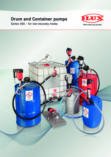
INSTRUCTION MANUALSUBMERSIBLE PUMPS12.07.0030.06.03Dat:No:94-BA 5079E/ 13d2.6MAINTENANCE AND SERVICE2.6.1GENERALFile:Q TAU EPay attention to the relevant instructions.Before doing any work on the pump unit, switch off main isolator switch and remove fuses from panel.The following checks (Section 2.6.3) can be done in the field. When a repair is indicated, send the pumpunit to the nearest authorized Hidrostal service station.CAUTION:When disconnecting the power cable at the control panel, take care that the cable ends CANNOT comein contact with water. Replace the plastic cable-end shipped with the pump (if this is no longer available,wrap the cable ends inside a plastic bag, and seal with tape) for water-tightness during handling andshipping.2.6.2COOLING TYPESHIDROSTAL submersible motors must be operatedsubmerged in the liquid for continuous duty (coolingtype: second digit of motor code).SUBMERSIBLE COOLING - Code "N"This type transfers motor heat directly through thestator housing to the surrounding ambient liquid.KEY FOR SYMBOLS ON FIG. 7:MOTOILF Opening "OIL"Opening "MOT"Motor room openingOil drain openingFlushing connection(see Section 2.2.3)Opening "F"Fig. 72.6.3FIELD TESTS2.6.3.1 VISUAL CHECKS AFTER PULLING PUMP UNIT FROM SUMP-Check pump and motor for possible mechanical damage. Pay attention to the cable.If pump volume or pressure are not acceptable, check impeller clearance (see manual for hydraulic).Check overload relay, fuses and time relays (if any) for correct setting.Check correct function of level control.Check insulation resistance of motor windings and cables with a high-voltage ohm-meter ("megger").This initial test should be made from the point where the cables attach to the motor starter. Check fromeach winding lead to the other two winding leads and to the ground lead.Tel. 0294-457712Fax 0294-457713
INSTRUCTION MANUALSUBMERSIBLE PUMPSDat:12.07.0094-BA 5079E/ 14dNo:File:Q TAU EINSULATION CHARTCONDITION OF MOTOR AND CABLESOHM VALUEA new motor.2'000'000 (or more)2A used motor which can be re-installed in the well.1'000'000 (or more)1MOTOR IN PIT. Ohm readings are for cable plus motor.A motor in the pit in reasonable good condition.MEGAOHM VALUE500'000 - 1'000'000A motor which may have been damaged by lightning or with damagedleads. Do not pull the pump for this reason.A motor which has wet or damaged cable or windings. The pump should bepulled soon and repairs made to the cable or the motor dried and replaced.The motor will not fail for this reason, but it will probably not operate for long.A motor which has failed or with completely destroyed cable insulation.The pump must be pulled and repaired or the motor replaced.The motor will probably not operate for long.The motor will not run in this condition.0.5 - 1.020'000 -500'0000.02 - 0.510'000 -20'0000.01 - 0.02Less than 10'00000- 0.010CAUTION:Do NOT "Megger test" control leads when thermistors are fitted: Voltages over 2,5 V will cause thermistorsto fail, and may destroy the winding.Any reading less than 1.0 Megaohm could indicate failure of cable or winding insulation. If failure isindicated, remove pump with cable and proceed to Section 2.7 for further tests.2.6.3.2 MOTOR HOUSING TESTThis test consists of a check on the condition of the motor side mechanical seal and/or motor housing "O"rings.Stand pump vertically on its suction flange. Remove screw plug "MOT" (Fig. 7) with copper washer (536)so that any liquid can run out. Do the following repairs according to what comes out of the motor housings:WATERMIXTURE WATER/OILOILNO LIQUID (DRY)}General overhaul with change of bearings and seals Change motor side mechanical seal (Pos. 516)Stator housing is OK. No defect.CAUTION:This screw plug must be completely watertight. Sealing surfaces must be clean and smooth beforeassembly. Heat new copper ring to dull red and immediately quench in water to soften copper ring for bestseal. All copper rings supplied by Hidrostal are softened.2.6.3.3 OIL CHECKING ON SUBMERSIBLE MOTORSThis is a check on the condition of the pump side mechanical seal. For pump units supplied with a moistureprobe, total failure of the pump side seal will be indicated by activation of the resistance relay. However,even without this circuit, a slow failure can be detected earlier by the following oil check.Oil checking must be done after the first 1'000 hours of operation and once a year thereafter.Immediately before checking, run the pump for a few minutes to distribute any impurities throughout theoil. Raise the pump out of the sump and clean it with a water hose.Tel. 0294-457712Fax 0294-457713
INSTRUCTION MANUALSUBMERSIBLE PUMPS12.07.0030.06.03Dat:No:94-BA 5079E/ 15eFile:Q TAU EOil level checkStand pump with shaft vertical, and remove screw plug marked "OIL". Coolant level must be at the levelof opening "OIL".If coolant is far below this level, the pump side mechanical sealmay have leaked and may require replacement (Section2.9.1). If oil level is only a small amount below this level,proceed with following test. Top-up with new oil and re-checkin 200-500 hours (Fig. 8).Oil quality checkLay pump down horizontally with opening "OIL" (536) upwards.Remove screw plug "OIL". Insert a tube or rubber hose, place Opening "OIL"a finger over top of tube and remove it with a small sample.Repeat until
SUBMERSIBLE PUMPS TABLE OF CONTENTS Part II 2.0 Use 2.1 Introduction 2.1.1 Type code explanation 2.2 Installation 2.2.1 Installation of pump guide system 2.2.2 Preparatory checks 2.2.3 Flushing water connection 2.2.4 Direction of rotation 2.2.5 Lowering the pump into the sump 2.3 Start-up 2.4 Electrical connection 2.4.1 Panel controls 2.4.1.1 .