Transcription
MANAGEMENT HANDBOOKSUBMERSIBLE PUMPS AND MOTORSX-POWER 3"- 4" - 6"- 8" - 10" SUBMERSIBLE ELECTRIC PUMPSX-POWER AMEGA 4" SUBMERSIBLE PUMPS3” - 4” - 6” - 8” - 10” SUBMERSIBLE MOTORS4” - 5” MONOBLOCK SUBMERSIBLE ELECTRIC PUMPSDetails:- MAX3 - MAX4 - AMEGA4 - GM4 - MAX6 X - MAX8 X - MAX10 X submersible pumps- 6C - 8C - 10C submersible motors- MX - MXW – MXA submersible motors-VTM monoblock pumps - VORTEX KIT - MAX4 PRESSION-Max5 monoblock pumps - EUROSUBwww.xpowerwaterpumps.com
www.xpowerwaterpumps.com
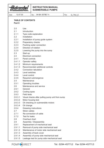
MA. X MAX.CMAX.X6C-8C-10CMXMXAMXWGM4MAX3VTMMAX4SLM15MAX4 PRESSIONMAX 4 KIT SLM15 KITMAX4 SBMAX4 SB KITAMEGA 4 SBAMEGA 4 SB KITwww.xpowerwaterpumps.comEUROSUBEUROSUB KITMAX5MAX5 KIT
INDEXPageo Symbols used in this manual4o Goods storage Storing4Io Products name4o Key features of the products5o Applications Pumped liquids Sound pressure level6q6S6o Preparations for installation Check the motor fluid level Positioning requirements Pump/motor diameter Pumped liquid cooling/temperature Pipe connection6C7R7P7R7A7o General electrical connection Operation with frequency converter Motor protection Electrical protection Electric cable dimensions Diagram for 2-phase single-phase motors Diagram for single-phase 3-wire motors Diagram for three-phase 3- wire motorso Installation Pump and motor coupling MAX4 cable protection (coupling) AX 6X – 8X – 10X cable protection Submersible cable connection Riser pipe Max. Installation depth below water level[m] Binding Lower the pump Depth of 16B16A16P16o Start-up and operation Start Runnig18o Water levels17o Maintenance work and assistance17o Monoblock pumps (assembly diagrams)SR1818/19o Cable and motor check21o Problems22o44o Introduction
(ex: long pumps), please connect the pumps as described in the"Pump and motor coupling" section.IntroductionThese instructions refer to submersible pumps andsubmersible motors:Hydraulics (submersible pumps)MAX3, SLM15, MAX4, GM4, AMEGA4, MAX6 X, MAX8 X,Submersible motorsMX, MXA, MXW, 6C, 8C, 10CSubmersible electric pumpsMAX3 KIT, SLM15 VORTEX KIT, MAX4 KIT, MAX4 SB KIT, GM4 KITAMEGA4 KIT, EUROSUB, MAX 5The identification plate supplied with the pump must be fixedin the installation area.Handle the pump carefully.Storage temperaturePump: from -20 C to 60 C.Electric pump: from -20 C to 60 C.Motor: from -20 C to 70 C.The motors must be stored in dry and ventilated places.In case of storage of the MX, MXA, MXW, C series motors it isrecommended to periodically check the device.1. Symbols used in this manualWARNING!Failure to observe precautions could result in injury topeople or damage to property.To prevent the risk of severe or fatal electrical shock, specialprecautions must be taken.WarningRead this manual carefully before installation. For correctoperation, always comply with local regulations.Rely only on qualified personnel.If the motor has been in storage for more than 12 monthsbefore its installation, the rotating parts of the motor mustbe dismantled and its functionality checked before use.The pump must not be exposed to direct sunlight. If the pumphas been unpacked, it must be placed in an horizontal positionand provided with a suitable support, or it must be positionedvertically to avoid misalignment.Make sure the pump can not roll or fall.During storage, the pump can be supported as shown in fig. 1.Fig.12. Goods storagePump position during storage.DeliveryThe pump must remain in the box until it will beinstalled.Handle the pump carefully.Antifreeze protectionIf the product is to be stored after a period of use, it must be placed in a placewhere no ice can form. Alternatively, provide a motor liquid antifreeze.If the hydraulics and the motors are supplied in separate unitswww.xpowerwaterpumps.com5
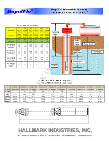
Main features of the products (motors, pumps and submersible pumps for wells)3 " MAX3 KIT - SLM15 KIT (named Vortex) Submersible electric pumpHIGH HYDRAULIC EFFICIENCY.LOW RESISTANCE TO THE SAND (to obtain a long life, the sand must not exceed 80 gr/cu.m).Efficient and lasting.Nominal diameter: 75mm for 3" wellsHeads: made of brass; Covering: made of AISI 304 stainless steel4” MAX4 KIT - GM4 KIT (named Vortex) Submersible electric pumpMEDIUM HYDRAULIC EFFICENCYHIGH RESISTANCE TO THE SAND (to obtain a high durability, the sand must not exceed 450 gr/cu.m)Submersible anti-sand hydraulicsNominal diameter: 100mm for 4 "wellsHeads and cover in AISI 304 stainless steel4” AMEGA 4 Hydraulics - 4” MAX4 SB KIT (named Amega) submersible electric pumpHIGH HYDRAULIC EFFICIENCYMEDIUM RESISTANCE TO THE SAND (to obtain a long life, the sand must not exceed 150 gr/cu.m)High hydraulic efficiency,Nominal diameter: 100mm for 4 "wellsBrass heads; pump cover in AISI 201 stainless steel; motor cover in AISI 304 stainless steel4” MAX4 - GM4 Pump - Hydraulics (named Vortex)MEDIUM HYDRAULIC EFFICENCYHIGH RESISTANCE TO THE SAND (to obtain a high durability, the sand must not exceed 450 gr /cu.m)Submersible anti-sand hydraulicsNominal diameter: 100mm for 4 "wellsHeads and cover in AISI 304 stainless steel6” MAX 6X Pump (hydraulics)HIGH HYDRAULIC EFFICIENCYMEDIUM RESISTANCE TO THE SAND (to obtain a long life, the sand must not exceed 80 gr/cu.m)Submersible pumps with high hydraulic efficiency,Nominal diameter: 140mm for 6 "wellsIntegrally made of AISI 304 stainless steel8” MAX 8X Pump (hydraulics)HIGH HYDRAULIC EFFICIENCYMEDIUM RESISTANCE TO THE SAND (to obtain a long life, the sand must not exceed 150 gr/cu.m)Submersible pumps with high hydraulic efficiencyNominal diameter: 200 mm for 4 "wellsIntegrally made of AISI 304 stainless steel10” MAX 10X Pump (hydraulics)HIGH HYDRAULIC EFFICIENCYMEDIUM RESISTANCE TO THE SAND (to obtain a long life, the sand must not exceed 150 gr/cu.m)Submersible pumps with high hydraulic efficiencyNominal diameter: 240 mm for 4 "wellsIntegrally made of AISI 304 stainless steel4” MX Submersible MotorHIGH HYDRAULIC EFFICIENCYMEDIUM RESISTANCE TO THE SAND (to obtain a long life, the sand must not exceed 150 gr/cu.m)4 "submersible motors with oil-immersed motor (3-pole earth output) Cover: AISI 201 stainless steel4” MXW watercooled submersible motorHIGH HYDRAULIC EFFICIENCYALTA RESISTENZA ALLA SABBIA (per ottenere una elevate durata, la sabbia non deve superare 450 gr/cu.m)4“ Water-cooled submersible motor water-immersed motor (3-pole earth output)Cover: AISI 304 stainless steel4” MXA submersible motorHIGH HYDRAULIC EFFICIENCYMEDIUM RESISTANCE TO THE SAND (to obtain a long life, the sand must not exceed 150 gr/cu.m)4" water-cooled submersible motor (2-pole ground)Cover: AISI 304 stainless steel6” 6C - 8” 8C - 10” 10C submersible motorsHIGH HYDRAULIC EFFICIENCYMEDIUM RESISTANCE TO THE SAND (to obtain a long life, the sand must not exceed 150 gr/cu.m)4" water-cooled submersible motor (2-pole ground)Cover: AISI 304 stainless steelwww.xpowerwaterpumps.com6
3. ApplicationsX-Power submersible pumps are very versatile items. They aresuitable for water supply, irrigation and technological use.The X-Power pumps must be installed in such a way that aminimum water head (1 to 2 meters) above the suction pipe issecured.These pumps can be installed horizontally or vertically.Pumped liquidsThese device pump clean, non-explosive liquids without solidparticles or fibers. The max sand content must not exceed thequantities reported in this manual.A higher concentration of sand decreases the life of the pump andincreases the risk of blockage.Note:4. Preparations for installationWarning:Before starting the installation, it is necessary to switch offthe power supply. Make sure the power supply can not beaccidentally reset.Check the motor fluid (Motors 6C - 8C - 10C)The motors are factory filled with a special non-toxic liquid thatresists freezing up to -20 C. Check the motor fluid level andtop up it if necessary with clean water. 4" motors do not requireliquid control.X-Power MX - MXW – MXA motorsIf the pump will be used for liquids with a densityhigher than that of water, it is necessary to usemotors with proportionally higher powers.The MX series motors are refrigerated in oil; they do not have top-up screwsand do not require special checks.The MXW and MXA motors are resin-bonded, they do not have topping upscrews and do not require special checks.Submersible motorsSOUND PRESSURE LEVEL (PUMP AND MOTOR)Sound pressure level of the MX – MXW – MXA motorsThe sound pressure level of the X-Power 4” submersible motors complies withthe Euro directive 2002/49 / CE 06/25/02.Sound pressure levelThe sound pressure level is measured in accordance with theEEC Machinery Directive 2006/42 / EC.Values are applicable for motors in standard production.Submerged hydraulicThe sound pressure level of the X-Power MX - MXW - MXA motors is less than60 dB (A).Sound pressure level of the MAX 3 , SLM 15,AMEGA 4, MAX 4, GM 4, MAX 6X, MAX 8X, MAX 10X PumpsValues are applicable for submersible pumps in water, withoutexternal control valve.Sound pressure level of the Max3, SLM15, Amega4, MAX4,GM4 PUMPSThe sound pressure level of the X-Power MAX3, SLM15, AMEGA4,MAX4, GM4 submersible pumps is less than 65 dB (A).Motor modelLpA [dB(A)]MX4 60MXW4 60MXA4 60Sound pressure level of 6C - 8C - 10C motorsThe sound pressure level of the X-Power 6 "- 8" - 10 " submersible motorscomplies with the Euro directive 2002/49/CE 06/25/02.Values are applicable for motors in standard production.Pump modelLpA [dB(A)]MAX3 - SLM15 65AMEGA4 - MAX4 - GM4 65To consult the noise level of the VTM VORTEX - MAX4 PRESSION- EUROSUB - MAX5 electric pumps, please consult this manual onpage 19-The sound pressure level of the X-Power 6C - 8C - 10C submersible motors isless than 65 dB (A).Motor modelLpA [dB(A)]6C 658C 6510C 65Sound pressure level of 6"- 8" - 10 "submersible pumpsThe sound pressure level of the X-Power MAX6 X - MAX 8X MAX 10X submersible pumps is less than 70 dB (A).Pump modelLpA [dB(A)]MAX6 X 70MAX8 X 70MAX 10X 707
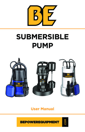
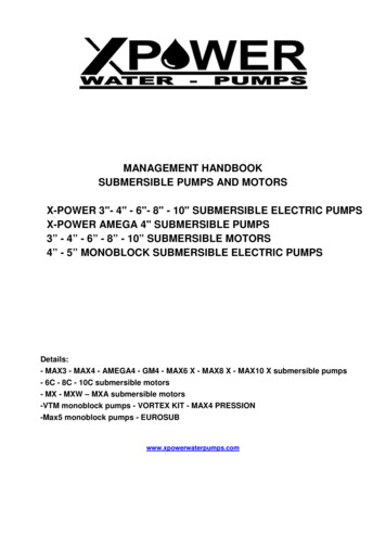
X-Power 6C – 8C – 10C motors (fig.01)Check and top up the liquid as described below (ref.fig.1):The filling hole for the motor liquid is located at the top of the device.1.2.3.4.Position the submersible pump with the 45 axis as shown in the following figure. The filler screw must be positioned at the top of the motor.Remove the screw from the filling hole.Inject the liquid into the motor with the filling syringe until the liquid comes out of the filling hole.Replace the screw in the filling hole and close the valve well before changing the position of the pump.Tightening torque 3,2 Nm.The submersible pump is ready for installationCheck the water level for the 6C - 8C - 10C motorsVerify that there are no leaks of liquid45 6C - 8C - 10C motors (fig.01)Motori X-Power MX – MXA - MXWMX - MXA - MXW motors (fig.02)(fig.02)MX - MXA - MXW motors do not require liquid level controls (ref.fig.2). However, it is necessary to check if the pump has liquid leaks. Incase of refrigerant liquid leaks, please contact the customer care immediately.Pipe connectionIf there is a possibility of making noise in the buildingthrough the pipes, it is advisable to use plastic pipes.When using plastic pipes, the pump must be secured with a safetyrope not fully tensioned.WarningMake sure that the plastic tubes are suitable for theliquid temperature and the pump pressure.When using plastic pipes, a compression fittingor UPVC pipe adapter must be used betweenthe pump and the first pipe section.Electrical connection (valid for all 3-wire earth motors and electric pumps)8
WarningDuring electrical installation,make sure that the power supply can not beaccidentally switched on.WarningPerform a good-Water Tightness ligature.The motor must be connected to the power cableusing the connection kit.1)2)3)SUBMERSIBLE PUMPSCONNECTION KITELECTRIC CONTROL PANEL OR ELECTRICAL EQUIPMENTWarning valid for all electric pumps and submersible motors.Ground the pump.The pump must be connected to an external main switchwith a minimum distance between contacts of 3 mm in all poles.9
WARNINGThe electrical installation must be carried outby qualified personnel, in compliance with current regulations.The supply voltage and the maximum rated current are expressed on the plate that must be affixed near the place of installation of the product.The required voltage quality for C-series motors is -10% / 6% of rated voltage during continuous operation (including change in supply voltage and cablelosses).N.B. Verify that there is symmetry of voltage in the power supply lines. E.g. the same voltage difference between the individual phases.Operation with frequency converter. X-Power MX - MXW – MXA single-phase motors.The X-Power MX, MXW, MXA, single-phase motors can be powered by a frequency converter with 1x230 single-phase power supply and 1x230 singlephase output.When operating with a frequency converter, do not run the motor at frequencies above 60 HzDuring the operation of the pump, never reduce the frequency (and consequently the rotation speed) to a level that can not guarantee theminimum flow for cooling the motor.To avoid damage to the pump, the motor must stop when the flow drops below 0.1 nominal flow.Depending on the type of frequency converter, the motor may be exposed to damaging voltage surges.WarningThe 4 "X-Power motors must be protected against voltage surges greater than 244 V (peak value) between the terminals.For more information, please contact the distributor.Operation with frequency converter for X-Power MXW - 6C - 8C - 10C motors.The three-phase X-Power motors can be powered by a frequency converter.Only for motors in special versionIf a motor with a temperature transmitter is powered by a frequency converter, the fuse inside the transmitter will burn out and the transmitterwill be irreversibly damaged. The transmitter can not be reactivated. This means that the motor will operate as if the temperature transmitterwere not present.For all motorsWhen operating with a frequency converter, do not run the motor at frequencies above 60 Hz.During the operation of the pump, never reduce the frequency (and consequently the rotation speed) to a level that can not guarantee theminimum flow for cooling the motor.To avoid damage to the pump, the motor must stop when the flow drops below 0.1 nominal flow.Depending on the type of frequency converter, the motor may be exposed to damaging voltage surges.Warning!The "C" series motors for supply voltages up to and including 440 V (see motor nameplate) must be protected against voltagepeaks above 650 V (peak value) between the terminals.It is recommended to protect all other motors from voltage peaks above 850 V.The aforementioned disturbance can be avoided by installing an RC filter between the frequency converter and the motor.Any increase in acoustic noise from the motor can be eliminated by installing an LC filter, which also eliminates voltage peaks from the frequencyconverter.We recommend installing an LC filter when using a frequency converter.For more information, contact the inverter distributor.10
Motor protection - electric pumpMotor protection and single-phase electric pumpsX-Power MXA single-phase motors and 2-wire electric pumpsThe MXA single-phase motors and the EURSUB CI pumps already have an integrated thermal switch and do not require additional protections.Warning!With the motor switched off thermally, the terminals are still powered.Once the motor has sufficiently cooled down, it will restart automatically.X-Power MXW single-phase motors and 3-wire electric pumpsThe MXW motors and single-phase electric pumps must be protected. The protective device can be incorporated into the control panel or suppliedseparately. The MXV X-Power motors and the electric pumps must be connected to a special protection switch.Motori monofase X-Power MXThe MX motors and single-phase electric pumps must be protected. The protective device can be incorporated into the control panel or suppliedseparately. The MX X-Power motors and the electric pumps must be connected to a special protection switch.MAX 3 - SLM 15 Vortex - VTM Vortex - MAX 4 PRESSION - MAX 4 KIT AMEGA 4 SB KIT - GM4 KIT Vortex EUROSUB CE - MAX5 KIT monoblock submersible pumps.The MAX 3 KIT, SLM 15 VORTEX KIT, VTM VORTEX KIT, MAX 4 PRESSION, AMEAG4 SB KIT, GM4 KIT, EUROSUB CE KIT, MAX 4 KITsubmersible pumps are supplied with electrical panel complete with condenser, switch and externally resettable thermal protection.Three-phase motor protectionX-Power MXW – MXA – MX - 6C – 8C – 10C motorsThe following motors must be protected by a protection switch with thermal relay or similar;MXW – MXA – MX – 6C – 8C – 10C motors.Required settings of the submersible motor protection switchFor cold motors, the tripping time of the protection switch must be less than 10 seconds at 5 times the maximum current of the motor. Under normaloperating conditions, the motor must run at maximum speed in less than 3 seconds.N.B. If this requirement is not met, the submersible motor warranty will not be validated.Optimal protection (choice of protection thermal setting)The protection switch must be installed as follows: Set the maximum current of 5% more than the current that normally absorbs the motor Start the pump and let it run for half an hour at normal performance. Slowly reduce the operating current until the thermal protection start point is reached. Increase the setting of 5%.For motors with a star/delta starting, the protection switch must be set as indicated above. The maximum setting must however correspond to themaximum rated current x 0.58.The maximum starting time allowed for star-delta starting or auto-transformer start is 2 seconds.11
Protection against lightningControl of single-phase MXA motorsThe system can be equipped with a special overvoltage protectiondevice, able to protect the motor from electrical voltage peaks dueto lightning.However, the overvoltage protection device can not protect themotor in the event of a direct lightning strike.The overvoltage protection device must be installed in the systemaccording to local regulations.Contact X-Power for lightning protection devices.The MS 402 motors, however, do not require additional lightningprotection because they are well insulated.Warning!The single-phase MXA motor includes a protectionthat stops the motor in case of excessive windingstemperature.If a compressor with an ocher filter is included in the control system. Thecompressor will continue to operate even when the thermal protection hasstopped the motor, unless other specific precautions are taken.Connection of single-phase motors and monoblock pumpswith internal condenserCable sizing2-wire motors (MXA)Make sure that the power cable is always immersed in the liquid atthe actual reference temperature of the calculation.The 2-wire MXA motors incorporate the protection mechanismand a starter and can therefore be connected directly to thepower supply.The cross-section (q) of the cable must meet the followingcharacteristics:BlackSo by summarizing it is always necessary to make sure that themaximum rated current does not exceed the current value (Is).Yellow/green1. The submerged cable must be dimensioned according tothe maximum rated current (I) of the motor.2. The section must not cause voltage drops.Connection of MXA (2-wire) and EUROSUB (2-wire) motorMAX 5 (2-wire)When the submersible cable is sized, you need to make sure that themaximum rated current does not exceed the current value (Is).For star-delta starting, dimension the cables so that 0.58 themaximum rated current of the motor does not exceed the value of thecurrent (Is) of the 5162300633
6 Connection of three-phase motorsThe three-phase motors must be shielded.The single-phase MXW motors include the appropriate protection andmust be connected to the power supply as follows:For electrical connection via thermal protection, refer to theseparately supplied installation manual.When using a conventional motor protection switch, the electricalconnection must be performed as described below.BrownBlue greyThe pump should only be started after the suctioninterconnector has been completely submerged belowthe water level.BlackYellow/greenRotation controlWhen the pump has been connected to the power supply, checkthe direction of rotation:1. Start the pump and, measure the amount of water and the prevalence.2. Stop the pump and exchange two phases between them.3. Start the pump and measure the amount of water and theprevalence.4. Stop the pump.MX - MXW (3-wire) motor connection5. Compare the two results to each other. The link that providesthe largest amount of water and the highest prevalence will bethe correct one.Motors with direct start-upThe connection of X-Power motors with direct start-up is shown inthe table below.Cable/connectionPower4” and 6” Motors3-wire motors (MX - MXW - MXA)The 3-wire MX and MXW motors must be connected to the mainssupply via a control panel and motor protection.The 3-wire MXA motors include the motor protection and theymust be installed with a control panel without motor protection.PE (yellow/green)L1U (brown)L2V (black)L3W (grey/ light blue)Check the direction of rotation as described in the"Control of rotation of three-phase motor" section.13
X-Power motors - star delta startingThe connection of the X-Power "C series" star-delta motorsis shown in the table belowConnectionPEX-Power da 6" motorsStar-delta starter motorsDetermine the motor windings by means of an ohmmeter.Regarding the conductors for the individual windings, refer to the figurebelow: U1-U2; V1-V2; ckV2GreyCheck the direction of rotation as described in the"Control of rotation of three-phase motor" section.PE L1 L2 L3If a star-delta starting is required, the terminals must be connected asshown in the figure on the left side, of this page.Check the direction of rotation as described in the"Check direction of rotation" sectionW2 U2 V2PE U1 V1 W1M3Wrapped motors - star-delta startingIf direct starting is required, the motors must beconnected as shown below.Soft starterX-Power recommends the use of "soft-start" devices. They are equipped with abypass switch, and they control the voltage across all the three phases.Starting time: Max. 3 seconds.For more information, please contact the soft-start device vendoror the X-Power.Operation with frequency converterThe three-phase "C Series" motors can be connected to a frequencyconverter.Permissible frequency ranges: 30-50 Hz and 30-60 Hz.Starting time: Max. 3 seconds.Depending on the model, the frequency converter can cause anincrease in motor noise. Furthermore, it could expose the motorto damaging voltage surges. Voltage peaks can be limited bysimply installing an LC filter between the frequency converter andthe motor.For more information, please contact the frequency device vendoror the X-Power.info@xpowerwaterpumps.com"C Series" X-Power motors wound for direct start-upConnection in case of unidentified connection/cable markingIf you do not know exactly where to connect the terminals to the mains supply, to ensure the correct direction of rotation, proceed as follows:Connect the motor to the mains supply in the way that is considered correct.Check the direction of rotation as described in the section.Control towards rotation.7. Installation for disjoint pumpsFirst of all, it is advisable to install a 50 cm long tube on thepump to facilitate handling during installation.14Place the pump in an upright position before removing it from thewooden box.
Raise the pump and couple it to the motor carefully. An incorrect coupling canseriously damage the electric pump.A mismatched coupling can cause a break in the crankshaft.Place the pump in vertical position.Make sure that the coupling between the pump andthe motor does not show any anomalies.Place the pump in vertical position1. Place the pump on top of the motor.2. Position and tighten the nuts. (See table below).Make sure that the coupling between the pump and the motordoes not show any anomalies.The bolts and nuts that secure the tie rods to the pump must be tightened in acrisscross pattern:Bolts/nutsTightening torque[Nm]M818M1035M1245M16120Join the motor to the pump and tighten the nuts in a crisscrosspatternDiameter of thetie rod3/81/2Tightening torque[Nm]1850M8M121870M16M2015028015
Pump and motor couplingWhen pump and motor are supplied in separately (as in the case of particularly long pumps), join the pump and motor as follows: When handling the motor, use the hose clamps. Place the motor in a vertical position in the well. See figure belowCoupling of the MAX4 and AMEGA submersible pumps and of the MX - MXW – MXA motors.16
Submersible cable connectionBefore connecting the submerged cable to the motor, make surethe outlet is dry and clean.To facilitate cable assembly, lubricate the rubber parts of the plugwith a non-conductive silicone adhesive.Tighten the screws that support the cable to these tighteningtorques [Nm]:Fix the components of the delivery pipeIt is necessary to avoid that the recoils of the submersible pumpcan cause dangerous displacements of the delivery pipecomponents. The electric cable and any safety rope must beeffectively interlocked with each other by means of safety ropes. Position the strips along the submersible cable as shown inthe figure belowHP 4 : 20 10HP 25 : 50 16.Riser pipeTo connect the discharge pipe to the pump, use a chain wrenchthat tightens the pump only on the discharge chamber.The threaded joints on the riser pipe must all be well cut andinstalled to prevent them from loosening.The thread on the first section of the riser tube to be screwed ontothe pump must not be longer than the threads on the pump.To avoid building noise caused by pipes, it is advisable to useplastic pipes. If you have to connect plastic pipes, a compressionfitting must be used between the pump and the first part of thepipe.When using flanged pipes, it is necessary to make a slot inthe flanges that allows the passage of the submerged cable(and in case it is installed, also of the water indicator tube) Wrap tightly the band around the wire and cord. With large submersible cables, it will be necessary to wrap thestrips several times. If plastic pipes are used, it is necessary to leave some spacebetween a band and the tube, because the plastic pipesexpand when they are under pressure. If flanged pipes are used, the strips must be applied above andbelow each joint.Put the pump in the wellMaximum installation depth below the waterlevel [mt]SLM 15 Kit 3”: 120 mtMax3 Kit 3”: 120 mtVTM Kit 4”: 100 mtMAX Pression Kit 4”: 100 mtEurosub - Eurosub Kit 5”: 20 mtBefore lowering the pump into the well or into the tank, it isadvisable to inspect the housing with an internal gauge to ensurethat the passage is not obstructed.Lower the pump into the well, slowly, taking care not to damage themotor cable and the submerged cable.CAUTIONNever lower or lift the pump using the motor cable.Max5 5” - Max5 Kit 5”: 20 mtAmega4 Kit 4”: 120 mtDepth of installationGM4 Kit 4”: 150 mtThe dynamic water level must always be above the pump suctionconnector.MX series 4”:125 mtMXW series 4”:150 mtMXA series 4”:150 mtC series 6”: 150 mtC series 8”: 150 mtThe minimum inlet pressure is indicated in the NPSH curve of thepump.The minimum safety margin must be 1 m. To allow the motor tocool properly, it must be positioned above the well filter.C series 10”:150 mtWhen the pump has been installed at the required depth, theinstallation must be completed by closing the wellhead.Loosen the safety rope so that it is not taut and lock it on thewellhead using the appropriate latches.In pumps connected to plastic pipes, the expansion of the pipes underload should be considered when establishing the installation depth.17
8. Starting and operationStartingWhen the pump has been connected correctly installed, it must bestarted with the drain valve closed at approximately 1/3.Check the direction of rotation as described in the "Checkdirection of rotation" section.RunMinimum flowThe flow rate of the pump must never be set at such levels as tonot be able to meet the motor cooling requirements (which areindicated in the pumped liquid section).Never exceed the maximum recommended starting frequency in the followinggeneral table:Frequency of starts and stopsWith impurities in the water, the valve must be opened gradually toget all impurities out. The pump must not be stopped until the wateris completely clean to avoid blocking the non-return valve.With the valve open, check the lowering of the water level to makesure that the pump is always submerged.The dynamic water level must always be above the pump suctionconnection.MotorsNumber of direct startsMXA - MXMin. 1 per year.Max. 50 per hour.Max. 280 per day.MXWMin. 1 per year.Max. 60 per hour.Max. 300 per day.6CMin. 1 per year.Max. 30 per hour.Max. 200 per day.8CMin. 1 per year.Max. 20 per hour.Max. 150 per day.10CMin. 1 per year.Max. 15 per hour.Max. 100 per day.CAUTION: AVOID THAT SUBMERSED MOTOR OR PUMP WORK WITHOUT WATER(see warnings listed below)Comparison of different water levels:9. Maintenance and assistanceMaintenance can be performed at authorized service centers.L1: Minimum level of installation depth below the water level.It is recommend at least 1 meter.L2: The depth compared to the dynamic level of water.L3: The depth compared to the static water level.L4: Lowering of the water level. This is the difference betweenthe dynamic and static levels of water.L5: Depth of installation.If the pump has a higher flow than the shaft, it is advisable toinstall a dry-running protection.If no electrodes or level switches are installed, the water level maydrop too much, and the pump will draw in air.WarningIf a pump has b
4. Replace the screw in the filling hole and close the valve well before changing the position of the pump. Tightening torque 3,2 Nm. The submersible pump is ready for installation Check the water level for the 6C - 8C - 10C motors Verify that there are no leaks of liquid 45 6C - 8C - 10C motors (fig.01) MX - MXA - MXW motors (fig.02)