Transcription
DEPARTMENT OF THE ARMY TECHNICAL MANUALTM 55-4018-1DEPARTMENT OF THE AIR FORCE TECHNICAL ORDERTO 38G1-6-21CUMMINSPT FUEL SYSTEMDEPARTMENTS OF THE ARMY AND THE AIR FORCESEPTEMBER 1956
This technical manual contains copyrighted materialDEPARTMENTS OF THE ARMY ANDTHE AIR FORCEWASHINGTON 26, DC., 5 September 1966TM 55-4018-1/TO 88G1-6-21 is published for the use of all concerned.[AG 406 (27Jul 56)]BY ORDER OF THE SECRETARICE OF THE ARMY AND THE AIR FORCE:MAXWELL D. TAYLOR,General, United States Army,Chief of StaffOFFICIAL:JOHN A. KLEIN,Major General, United States Army,The Adjutant General.N. F. TWINING,Chief of Staff, United States Air Force.OFFICIAL:E. E. TORO,Colonel, United States Air Force,Air Adjutant General.DISTRIBUTION:Active Army:Tec Svc, DA (2)Army Maint Bd (2)Trans Bd (1)Mq CONARC (2)Army AA Comd (2)OS Maj Comd (2)OS Base Comd (1)Log Comd (2)MDW (1)Armies (2)Trans Sup & Maint Comd (15)Trans Sch (NG: None.USAR: None.For explanation of abbreviations used, seeU.S. GOVERNMENT PRINTING OFFICE:Trans Sec, Gen Depots (5)Trans Depots (5)POE (OS) (1)Trans Terminal Comd (1)Army Terminal (1)OS Sup Agencies (1)
TABLE OF CONTENTSSECTION IOperating Principles .1-1 to 1-6Fuel Pump .1-2Gear Pump .1-2Pressure Regulator .1-3Throttle, .1-3Governors.1-3Injectors.1-5Supply Lines .1-6Shut-down Valve.1-6Inlet Connections .1-6Drain Lines .1-6SECTION IIFuel System Installation .2-1 to 2-8Changing Systems.2-1Fuel Pump .2-1Injectors.2-1Fuel Manifolds .2-2Drive Coupling .2-2Fuel Supply Tank.2-3Fuel Lines .2-3Installation Diagrams .2-4Shut-down Valve.2-4Tachometer Cable .2-4Saddle Tanks .2-4SECTION IIIService and Adjustments .3-1 to 3-5Fuel Pump Screen .3-1Fuel Filter Element Changes.3-1Injector Adjustment. .3-2Governor Adjustments .3-2Checking a PT Pump on the Engine .3-4Cleaning Injectors on the Engine.3-4SECTION IVFuel Pump Assembly and Disassembly .4-1 to 4-26Disassembly .4-1Unit Rebuilding .4-5Assembly .4-15Testing.4-20SECTION VMaintenance and Testing of Injectors .5-1 to 5-2SECTION VITrouble-Shooting the Fuel System .6-1 to 6-243
INDEXAdjusting engine idle speed. 3-2Adjusting fuel pump on engine . 3-4Adjusting injectors . 3-2Adjusting standard governor. 3-2Adjusting torque converter governor. 3-3Adjusting variable-speed governor . 3-3Air leak check . 4-23Assembly of fuel pump. 4-15Calibration of fuel pump . 4-20Calibration of fuel pump on engine. 3-4Calibration pressures. 4-20, 4-24Capscrews and washers . 4-6Change fuel filter. 3-1Changing fuel systems . 2-1Clean fuel pump screen . 3-1Clean injectors . 5-1Clean injectors on engine . 3-4Governor spring pack assembly.4-4, 4-16Governor, torque converter.1-4, 3-3Governor, variable-speed .1-4, 3-3, 4-17Governed speed . 4-20, 4-22, 4-23, 4-24Idle governor .1-3, 3-2, 4-16Injectors .1-5, 2-1, 3-2, 5-1Injector adjustment .3-2Injector cleaning, bench.5-1Injector cleaning, on engine .3-4Inlet manifold.2-2Main housing .4-6Manifold orifice .4-20Manifold pressure . 4-20, 4-22, 4-24Material for calibrating pumps .4-21Maximum speed governor .1-3, 3-2, 4-16Needle bearings.4-6Diagram, fuel piping . 2-4Disassembly, fuel pump . . 4-1Disassembly, injector . 5-1Drain manifold. 1-6, 2-2Drive coupling . 2-2Drive shaft bushing . . 4-6Front cover assembly. 4-2, 4-9Fuel filter. 2-3, 3-1, 4-4, 4-15Fuel inlet connections . . 1-6, 2-1Fuel lines . 1-2, 1-6, 2-2, 2-.Fuel manifolds . 1-6, 2-2Fuel pressure adjustments . 3-4, 4-21Fuel pump. 1-2, 2-1, 4-1, 4-20Fuel pump assembly . 4-15Fuel pump disassembly . 4-1Fuel supply tank. 2-3, 4-21Fuel system installation. 2-1Gear pump. 1-2, 4-2, 4-7General instructions . 4-5Governor barrel. 4-7Governor disassembly. 4-10Governor, idle and maximum speed. 1-3, 3-2, 4-16Governor plunger . 4-2, 4-8, 4-18Governor spring guide . 4-16Operating principles.1-1Orifice specifications .4-21Orifice, idle .4-21Orifice, manifold .4-21Orifice, cleaning .5-1Parts replacement .4-6Piping, fuel .2-4Pressing lubricant .4-6Pressure regulator . 1-3, 4-1, 4-19, 4-22Pressure regulator spring load .4-22Pressure regulator setting . 4-20, 4-22, 4-24Priming the pump .3-2Pump, check on engine .3-4Pump gear.1-2, 4-3, 4-7Pump testing .4-20Screen, fuel .3-1, 4-4, 4-15Section I Operation Principles .1-1Section II Fuel System Installation .2-1Section III Fuel System Service andAdjustments .3-1Section IV Fuel Pump Assembly andDisassembly.4-1
INDEXTest equipment .3-4, 4-21, 5-1Throttle.1-3, 4-2, 4-18Throttle sleeve.4-7Throttle leakage. 4-20, 4-23, 4-24Tools .4-5Torque converter governor .1-4, 3-3Trouble shooting .6-1Trouble shooting charts .6-12Unit rebuilding .4-5Variable-speed governor.1-4, 3-3Vise and holding fixture .4-1Section V Maintenance of Injectors . 5-1Section VI Trouble Shooting theFuel System. 6.1Service and adjustments . 3-1Shut-down valve . 1-6, 2-3, 4-19Spring pack housing . 4-4, 4-16Supply lines . 1-6, 2-3Table, injector adjustment . 3-2Table, idle speed . 4-20, 4-24Table, manifold pressure. 4-20, 4-24Tachometer drive. 4-5, 4-8, 4-155
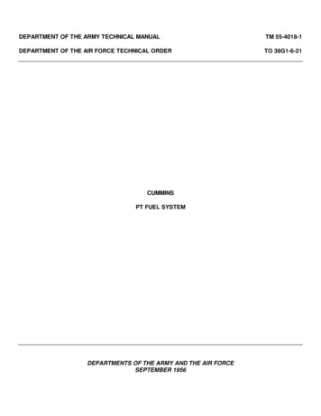
PT fuel pump with maximum speed governorPT fuel pump with variable speed governorPT fuel pump with torque converter governor
Operation and MaintenanceCUMMINS PT FUEL SYSTEMSECTION IOperating Principlesthrough a pipe you change the amount of liquid comingout of the open end: Increasing the pressure increasesthe flow or the amount of liquid delivered, and vice versa.In applying this simple principle to the diesel fuel system itwas necessary to provide:1. A fuel pump to draw fuel from the fuel tankCummins PT Fuel System is a completely newapplication of basic hydraulic principles to the dieselengine fuel system. It is a Cummins design for CumminsDiesels. The identifying letters, "PT," are an abbreviationfor "pressure-time."The principle of the PT Fuel System is based on thefact that by changing the pressure of a liquid flowingFigure 1-1. PT fuel system-Fuel flow diagram1-1
and deliver it to individual injectors for eachcylinder.2. A means of controlling the pressure of the fuelbeing delivered by the fuel pump to the injectorsso the individual cylinders would receive the rightamount of fuel for the power required of theengine.3. Fuel passages of the proper size and type so thatthe fuel will be distributed to all injectors andcylinders with equal pressure under all speed andload conditions.4. Injectors to receive low-pressure fuel from thefuel pump and deliver it into the individualcombustion chambers at the right time, in equalquantity and proper condition to burn.The PT Fuel System consists of the fuel pump (withgovernor), the supply and drain lines, and the injectors.Each of these is described in detail in the paragraphsfollowing.Fuel PumpThe fuel timing is made up of three main units:1. A gear pump which draws fuel from the supplytank and delivers it under pressure through thepump and supply lines to the individual injector.2. The pressure regulator which limits the pressureof the fuel to the injectors.3. The governor and throttle which act independentlyof the pressure regulator to control fuel pressureto the injectors.The fuel pump is coupled to the compressor or fuelpump drive which is driven from the engine gear train.The fuel pump main shaft turns at engine crankshaftspeed, and drives the gear pump, governor andtachometer shaft.The location of these units in the fuel pump housing isindicated in Fig. 1-2.GEAR PUMP: The gear pump is located at the rear ofthe fuel pump and it is driven by theFigure 1-2. Cross section PT pump with idling and high speed mechanical governor1-2
Figure 1-3. Fuel flow through the fuel pumpthrottle control in idle position and second; it cuts off fuelabove maximum rated rpm. The idle springs in thegovernor spring pack position the governor plunger so theidle fuel jet is opened enough to permit passage of fuel tomaintain engine idle speed.main shaft. This unit consists of a single set of gears topick-up and deliver fuel throughout the fuel system. Fromthe gear pump fuel flows through the filter screen and tothe pressure regulator.PRESSURE REGULATOR: 'The pressure regulator is aby-pass valve to regulate the fuel, under pressure,supplied to the injectors. By-passed fuel flows back to thesuction side of the gear pump.During operation between idle and maximum speeds,fuel flows through the governor to the injectors in accordwith the engine requirements as controlled by the throttleand limited by the pressure regulator. When the enginereaches governed speed, the governor weights move thegovernor plunger and fuel passages to the fuel supplymanifold are shut off. At the same time another passageopens and dumps the fuel to the supply manifold backinto the main pump body. In this manner engine speed iscontrolled and limited by the governor regardless ofthrottle position.Fuel leaving the governor travelsthrough the shut-down valve, inlet supply lines and on intothe injectors.THROTTLE: Fuel for the engine flows past the pressureregulator to the throttle shaft. Idle fuel passes around theshaft to the idle jet in the governor. For operation aboveidle, fuel passes through the throttling hole in the shaftand enters the governor through the primary jets.IDLING AND HIGH-SPEED MECHANICAL GOVERNOR:Mechanical governor action is provided by a system ofsprings and weights, and it has two functions. First; thegovernor maintains sufficient fuel for idling with the1-3
constant speed but where extremely close regulation isnot necessary.Adjustment for different rpm can be made by meansof a lever control or adjusting screw. At full-rated speed,this governor this a speed droop between full-load anti noload of approximately eight percent. A cross-section ofthis governor is shown in Fig. 1-4.As a variable-speed governor, this unit is suited to thevarying speed requirements of cranes, shovels, etc., inwhich the same engine is used for propelling the unit anddriving a pump or other fixed-speed machine.As a constant-speed governor, this unit providescontrol for pumps, nonparalleled generators and otherapplications where close regulation (variation between noload and full-load speeds) is not required.TORQUE CONVERTER GOVERNOR: When a torqueconverter is used to connect the engine with its drivenunit, an auxiliary governor may be driven off the torqueconverter output shaft toFigure 1-4. Flange mounted fuel pump with variablespeed governorVARIABLE-SPEED MECHANICAL GOVERNOR: Thisgovernor is designed to meet the requirements ofmachinery on which tile engine must operate at aFigure 1-5. Cross Action and fuel flow through torque converter governor and fuel pump1-4
exercise control over the engine governor and to limitconverter output shaft speed. The engine governor andthe converter governor must be adjusted to work together.The PT torque converter governor is fundamentallytwo mechanical variable-speed governors in series - -onedriven by the engine and the other by the converter. SeeFigs. 1-4 & 1-5.The engine governor, in addition to giving a variableengine speed acts as an overspeed and idle-speedgovernor while the converter-driven governor iscontrolling the engine. Each governor has its own controllever and speed adjusting screws.The converter driven governor works on the sameprinciples as the standard engine governor except itcannot cut off fuel to the idle jet in the engine drivengovernor. This insures that if the converter tailshaftoverspeeds it will not stop the engine. See Fig. 1-5.Fig. 1-5 shows the position of the governor plungersunder different engine and converter speed conditions.InjectorsFuel circulates through the injector at all times exceptduring a short period following injection into the cylinder.From the inlet connection fuel flows down the inletpassage of the injector, around the injector plunger,Figure 1-6. Injector cross sectionbetween the body end and cup, up the drain passage tothe drain connections and manifold and back to thesupply tank.1-5
Valve can not be reopened by switch key until after enginecomes to complete stop. If the key is turned "OFF", then"ON", while the engine is being pushed by its load (like atruck coasting downhill) the shut-down valve solenoid mayburn out as it tries to open the valve against the built-upfuel pressure.Never leave switch key or over-ride button in valve-openor run position when engine is not running.Withoverhead tanks this would allow fuel to drain into cylinderscausing a hydraulic lock.As the plunger comes up the injector feed passage isopened and fuel flows through the metering orifice intothe cup, at the same time fuel flows past the cup and outthe drain orifice. The amount of fuel which enters the cupis controlled by the fuel pressure against the meteringorifice. Fuel pressure is controlled by the fuel pump aspreviously described.The plunger during injection comes down until themetering orifice is closed and the fuel in the cup isinjected into the cylinder. While the plunger is seated inthe cup all fuel flow in tile injector is stopped.SUPPLY LINES: Fuel from the fuel pump must flowthrough lines to get to the injectors. These lines must beheld to a specified size to insure an even pressure andsupply of fuel to each injector. From the supply lines fuelenters the inletconnection to the injector.Supply LinesSHUT-DOWN VALVE: There are two shut-down valvesused on the PT fuel pump, a manual "push-pull" type andan electrically actuated valve.The manual valve is used on fuel pumps where the fueltank is lower than the fuel pump. To start the engine"push" in the valve cable knob; pull to stop. Keep thevalve in the "out" position at all times the engine is notrunning.The electric valve is always used where the installationhas an overhead tank.A manual over-ride button is provided on the forward endof the electric shut-down valve above the fuel pump. Itallows the valve to be opened in case of electric powerfailure. To use, turn to right.The engine can be shut down completely by turning offthe switch key on installations with an electric shut-downvalve. Turning off the key always stops the engine unlessover-ride button has been locked in open position.INLET CONNECTIONS: The inlet connection connectsthe supply fuel manifold to the injector and contains a finemesh screen at the large or cage end. This screen is thelast protection against dirt entering the injector. There areno check valves in the inlet connection used in the PTfuel system.DRAIN LINES: Not all the fuel entering the injector isburned in the cylinder. A set proportion circulates throughthe injector and is returned to the supply tank through thedrain fittings, drain manifold and drain line. The drainlines must also be held to a specified size to preventrestrictions on the injectors.1-6
SECTION IIFuel System InstallationChanging Fuel SystemsThe PT fuel system can be adapted to mostCummins Engines by making the changes described inthe following paragraphs. The complete fuel system ischanged including the fuel pump, inlet connections, fuellines and injectors. Conversion parts are available tochange the fuel pump drive or air compressor-to fuelpump drive coupling.Parts described in this section can be obtained aslisted in the PT Parts Book, Bulletin 6369.FUEL PUMP: The fuel pump is a completely new unitwhich mounts to a bracket with three cap screws,lockwashers, and two dowels or in case of L, LR andNHH engines is flange mounted. The bracket in turnmounts over similar dowels as used for the DD pumpbracket or Single-Disc fuel pump and is held in placewith cap screws. It is not necessary to time the pump tothe engine and timing marks are to be disregarded.1. Assemble the bracket to the fuel pump.2. Assemble the pump and bracket to the engineblock, see "Drive Coupling."Figure 2-1. Assembling injectorshold-down nuts over the studs, but do not tighten.Fig. 2-2.5. Screw in the fuel inlet and drain connectionsabout 3 or 4 turns. This is to align the injector body withthe fuel connections so the connecting gaskets will seatsquarely on the face of the injector. The old inletconnections must be replaced with new connections,see parts books for part numbers. Fig. 2-3.INJECTORS: The injectors used with the disc-type fuelpumps must be replaced by a complete set of newinjectors, especially designed for the PT fuel system.See Fig. 1-3.1. The new injectors do not have a cover and thusthe flange thickness is less than on the ones removed.The injector studs in the cylinder head must be changedor spacers used over the studs.2. Clean the injector seat with a clean rag wrappedaround a wooden stick. Never use a screw driver or ametal tool for this operation; a scratched seat may causea compression leak.3. Assemble the injectors in position. Fig. 2-1.CAUTION:BE CAREFUL NOT TO DAMAGE THEINJECTOR TIP.Figure 2-2. Injector hold-down nuts6. Torque the injector stud nuts in alternate stepsof 2 ft. lbs. to:4. Assemble the spacers, if used and injector2-1
a. 0 to 8 foot-pounds for the J series engine.b. 10 to 12 foot-pounds for tile 11, Nil, VTand NVH series engines.c. 15 to 20 foot-pounds for L and LRengines.7. Tighten the fuel inlet connections to 20/25 footpounds on all engines except the L and LR; tighten Land LR connections to 75 to 80 foot, pounds.8. Make injector adjustments as outlined on Page3-2.1. Remove the old spider coupling and assemblethe adapter coupling to the air compressor or driveshaft. Fig. 2-4.2. Assemble the coupling half to the adaptercoupling on the compressor or drive unit.FUEL MANIFOLDS:Inlet Manifold 1. The injectorsupply tubes are replaced with a fuel manifold. Fig. 2-3The connecting point between the two sections alsoserves as a fuel inlet connection from the fuel pump onall engines except the JS. The JS uses a one-piecemanifold with brazed connector. See "Fuel PipingDiagrams."2. The line from the fuel pump shutoff valve to thefuel manifold must be 5/16 inch tubing. It is essentialthat the proper size tubing be used throughout thecomplete fuel system to insure the proper flow offuel.Figure 2-4. Coupling rubber buffer3. Assemble the rubber buffer to the coupling Fig.2-4.Drain Manifold: 1. The injector drain manifold isreplaced with a new brazed manifold. Fig. 2-3.2. A line must lead from the drain manifold to thetop of the fuel supply tank. This must be No. 8Stratoflex or equivalent hose. See "Fuel Supply Tank"and Figs. 2-9, 2-10. 2-11 and 2-12.Figure 2-5. Coupling clearance4. Mount the fuel pump and bracket to the cylinderblock and measure the clearance between the couplinghalves. Fig. 2-5. This clearance should be 1/16 inch.Clearance can be adjusted by adding or removingshims. Fig. 2-6.5. Check the concentricity of the couplings, theymust be concentric within .015 inch total indicated runout. This can be regulated by adding shims between thefuel pump and bracket. Fig. 2-7.Figure 2-3. Inlet and drain manifoldsDRIVE COUPLINGS: The PT fuel pump is driven by aflexible rubber jaw-type coupling; adapter couplings areavailable to change spiders used on air compressors ofdrive units. This coupling requires shims to maintain theproper axial clearance between coupling halves.2-2
of liquid and fumes coming from the return lines to thetank. In installation where the use of an "air dome" isnecessary, an additional vent must be provided asshown in Fig. 2-11. This air dome must be at least 5inches high and 2 1/2 inches I.D. A vented filler spoutof size equal to the air dome may be used provided thevent hole is 1/8 inch in diameter. Air vent must hebelow level of injector in all cases except where anoverhead tank is used.2. To avoid overflow of fuel in hot weather the fueltank should be designed so it will hold only 95% of itstotal capacity.3. The fuel filter should be readily accessible andshould be located level with or higher than the fuelpump to facilitate starting. It is best to locate the filterunder the hood for cold weather operation.4. Make sure all suction line connections to thepump are air tight, with the outlet from the tank in thecenter and 3/4 inch above botton of tank. This may be abottom connection or a pipe from any location reachingto the bottom center of the tank.5. The injector drain connection in the tank shouldbe located near end of the tank above surface of thefuel and separated from the suction inlet by at least 12inches.6. A sump should be provided in the tank to drainsediment and water. See Fig. 2-14.7. For installations which are subject to I.C.C.regulations, it is recommended that fuel line or ventlocation and protection be made to conform with I.C.C.specifications.8. An overhead tank installation should be usedunder any condition where fuel might possibly syphonback to the injectors.9. In any installation the tank location should:a. Not be more than 8 feet above the pump.b. Bottom of tank must not be more than 8feet below the pump.10. External connections must not extend morethan 3/4 inch below bottom of the tank.Figure 2-6. Adding shims to couplingFigure 2-7. Checking coupling concentricity6. Remove the fuel pump and bracket, add shimsif required, and then mount the pump back on theengine.FUEL SUPPLY TANK: The fuel supply tank with thisfuel system serves a dual purpose. First it contains thefuel supply and; second it acts the same as a floatchamber on other Cummins fuel systems, i.e., itreceives fuel from the injector drain manifold. Fuelwhich circulates through the injectors carries heat fromtile injectors back to the tank. Under cold weatherconditions this heated or warm fuel will aid in preventionof frozen fuel lines.The following tank and piping instructions refer toFigures 2-9, 2-10, 2-11, 2-12, 2-13, and 2-14 shown onsucceeding pages:1. Venting arrangements shown are representativeof conditions required for separationFUEL LINES: Following is a table of line sizes fordifferent engines and the various locations: See Fig. 28 and pages 2-4 and 2-5.2-3
LineLocationSupply tank to filt
pump drive which is driven from the engine gear train. The fuel pump main shaft turns at engine crankshaft speed, and drives the gear pump, governor and tachometer shaft. The location of these units in the fuel pump housing is indicated in Fig. 1-2. GEAR PUMP: The gear pump is located at the rear of the fuel pump and it is driven by the Figure 1-2.