Transcription
4” and 6”SUBMERSIBLE PUMPSOWNER'S MANUALREAD AND FOLLOW SAFETY INSTRUCTIONSThis is the safety alert symbol. When you seethis symbol on your pump or in this manual, lookfor one of the following signal words and be alert to thepotential for personal injury:D A N G E R warns about hazards thatwill causeserious personal injury, death or major propertydamage if ignored.W A R N I N G warns about hazards that can causeserious personal injury, death or major propertydamage if ignored.C A U T I O N warns about hazards that will or cancause minor personal injury or major property damageif ignored.The label NOTICE indicates special instructions, whichare important but not related to hazards.Carefully read and follow all safety instructions inthis manual and on pump.Keep safety labels in good condition.Replace missing or damaged safety labels.WA R N I N GBEFORE INSTALLING PUMP, BE SURE TO READTHIS OWNER’S MANUAL CAREFULLY.C A U T I O N Fill pump with water before starting orpump will be damaged. The motor on this pump isguaranteed by the manufacturer. In event of failureit must be returned to an authorized service stationfor repairs. Motor warranty is void if repairs are notmade by an authorized repair station.INSPECT THE SHIPMENTExamine the pump when it is received to be sure therehas been no damage in shipping. Should any be evident,report it immediately to the dealer from whom the pumpwas purchased. Please check the pump package to seethat it includes pump, motor, and motor leads (if yourpump purchase includes a motor).Hazardous voltage.Can shock, burn, orcause death.Ground pump beforeconnecting to powersupply. Disconnectpower before workingon pump, motoror tank.W A R N I N G Wire motorfor correct voltage. See“Electrical” section ofthis manual and motornameplate.W A R N I N G Ground motorbefore connecting to powersupply.W A R N I N G Meet NationalElectrical Code, CanadianElectrical Code, and localcodes for all wiring.Follow wiring instructions inthis manual when connecting motor to power lines.106467101Rev. 1109.13
WARNINGIMPORTANT INFORMATION FORINSTALLERS OF THIS EQUIPMENT!THIS EQUIPMENT IS INTENDED FORINSTALLATION BY TECHNICALLY QUALIFIEDPERSONNEL. FAILURE TO INSTALL IT INCOMPLIANCE WITH NATIONAL AND LOCALELECTRICAL CODES, AND WITH FRANKLINELECTRIC RECOMMENDATIONS, MAY RESULTIN ELECTRICAL SHOCK OR FIRE HAZARD,UNSATISFACTORY PERFORMANCE, ANDEQUIPMENT FAILURE. FRANKLIN INSTALLATIONINFORMATION IS AVAILABLE FROM PUMPMANUFACTURERS AND DISTRIBUTORS, ANDDIRECTLY FROM FRANKLIN ELECTRIC. CALLFRANKLIN TOLL FREE 800-348-2420 FORINFORMATION. RETAIN THIS INFORMATIONSHEET WITH THE EQUIPMENT FOR FUTUREREFERENCE.WARNINGSERIOUS OR FATAL ELECTRICAL SHOCK MAYRESULT FROM FAILURE TO CONNECT THE MOTOR,CONTROL ENCLOSURES, METAL PLUMBING, ANDALL OTHER METAL NEAR THE MOTOR OR CABLE,TO THE POWER SUPPLY GROUND TERMINALUSING WIRE NO SMALLER THAN MOTOR CABLEWIRES. TO REDUCE RISK OF ELECTRICAL SHOCK,DISCONNECT POWER BEFORE WORKING ONOR AROUND THE WATER SYSTEM. DO NOT USEMOTOR IN SWIMMING AREAS.INSTALLATION RECORDSIt is good idea to keep an accurate record of yourinstallation. Be sure to record the data below:Purchased From:Date of Installation:Pump Model No.*Pump Date Code*Well Inside Dia.(in/mm):Depth of Well(ft/m):Depth of Water(ft/m):Pump Setting(ft/m):Drop Pipe Size:Wire Size(pump to control box):Wire Size(control box to power source):Horizontal Offset(between well & house):Make of Motor*AmpsHPVoltsPhMake of Control BoxHPVoltsPower SupplyVoltsHZPressure Switch (PSI)Cut-inCut-out* This Information is on your pump or motor tag. It willhelp us identify your pump in case of later inquiries.TEST RUNNINGIf test running pump before installation:1. Insure that the power supply corresponds with thatshown on the nameplate of the motor and controlbox. (if required).2. Install pump and components appropriate for thetest as shown in Fig. 1.3. Make sure power supply is turned off and circuitbreaker or disconnect switch is open. Makeelectrical connections appropriate to your motor asshown in Fig. 2, 3 or 4.4. THREE-PHASE UNIT - A three-phase motorrequires a magnetic starter equipped with quick-trip,ambient compensated heaters of correct size for thehorsepower of the motor. To insure correct rotationof three-phase units, brace pump shell securely andapply power momentarily by snapping line switchquickly on and off.2
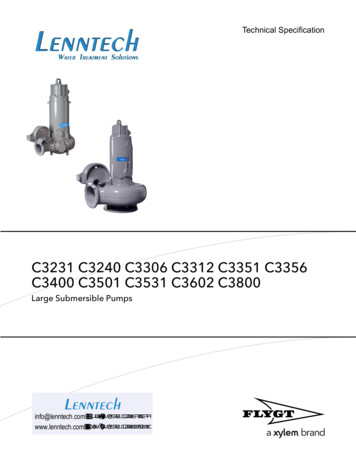
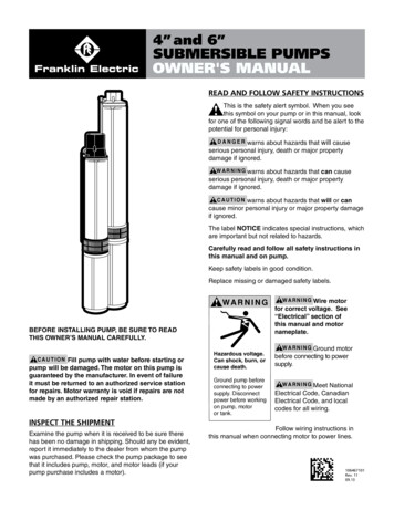
If rotation is correct, reaction of the shell will beclockwise when viewed from pump discharge(that is, pump shaft will rotate counter clockwise).Interchange any two leads at magnetic starter toreverse rotation.5. Run pump and motor unit for a few seconds toensure that it is in working order.FIGURE 1 - Installation Diagram2. Torque arrestor just above pump to prevent chafingthe cable when pump and pipe twist during thestarting and stopping cycle. (See Figure 1)Pressure TankSee Wiring DiagramsPressure SwitchSanitary Well Sealor Pitless AdapterSpring-LoadedCheck ValveGate ValveDischarge PipeSubmersible CablePressure Relief ValveService PipeSafety CableSubmersible Cable(secured to droppipe with tape orclamps every 10’/3m)Torque ArrestorWell CasingSpring-LoadedCheck Valveat Pump DischargeSubmersiblePump UnitSuction ScreenTake great care to keep pipes clean and free frompebbles, scale and thread chips. Make sound, air-tightconnections at all fittings. Pipe sealant is recommended.Pressure GaugeSpring-LoadedCheck Valve(Recommended every 100’/30m)Drop PipeNOTICE: IT IS RECOMMENDED THAT STEEL CABLEBE USED FOR THE PURPOSES OF SECURING THEPUMP. 3/16" DIAMETER TO 1/4" DIAMETER BRAIDEDSTEEL CABLE IS SUFFICIENT TO SUPPORT MOSTPUMP/MOTOR ASSEMBLIES. IT IS ALWAYS BESTTO CONFIRM THAT THE PUMP/MOTOR ASSEMBLYDOES NOT EXCEED THE MAXIMUM WEIGHT LIMITOF THE CABLE SELECTED.Note: Keep pump at least 5’ frombottom of well and above well screenor casing perforations.MotorWell Screen orCasing PerforationsSUITABILITY OF WELLInstall the pump only in a well that has been properlydeveloped. Water from an undeveloped well often containsan excessive amount of sand, dirt, and abrasives whichcan damage the pump. Check that the well is large enoughto allow the pump to be set at the required depth. Do notset the pump below the casing perforations or well screenunless you make arrangements to ensure an adequateflow of water over the motor for cooling purposes.Determine the correct pump setting from the driller’srecord by taking into account the static water level and thedrawdown at the proposed pumping rate. Keep the pumpat least five feet from the bottom of a drilled well.SPLICING THE POWER CABLEFollow the instructions enclosed in the cable splicingkit you purchase.DROP PIPEDrop pipe is recommended for suspendingsubmersible pumps into the well. Please refer to pipemanufacturer for recommendations on depth andpressure. Give special consideration to:CHECK VALVESIt is recommended that one or more check valvesalways be used in submersible pump installations. Ifthe pump does not have a built-in check valve, an inlinecheck valve should be installed in the discharge linewithin 25 feet of the pump and below the draw downlevel of the water supply. For deeper settings, checkvalves should be installed per the manufacturer'srecommendations. More than one check valve is oftenneeded, but more than the recommended number ofcheck valves should not be used.Swing type check valves are not acceptable and shouldnever be used with submersible motors/pumps. Swingtype check valves have a slower reaction time whichcan cause water hammer (see next page). Internalpump check valves or spring loaded check valves closequickly and help eliminate water hammer.NOTE: Only positive sealing check valves should beused in submersible installations. Although drilling thecheck valve or using drain-back check valves mayprevent back spinning, they create upthrust and waterhammer problems.Check valves are used to hold pressure in the systemwhen the pump stops. They also prevent backspin,water hammer and upthrust. Any of these can lead toearly pump or motor failure.A. Backspin - With no check valve or a failed checkvalve, the water in the drop pipe and the water in thesystem can flow down the discharge pipe when the motorstops. This can cause the pump to rotate in a reversedirection. If the motor is started while it is backspinning,1. A safety cable to prevent loss of pump if pipeshould break.3
an excessive force is placed across the pump-motorassembly that can cause impeller damage, motor orpump shaft breakage, excessive bearing wear, etc.B. Upthrust - With no check valve, a leaking checkvalve, or drilled check valve, the unit starts under a zerohead condition. This causes an uplifting or upthrust onthe impeller-shaft assembly in the pump. This upwardmovement carries across the pump-motor coupling andcreates an upthrust condition in the motor. Repeatedupthrust can cause premature failure of both the pumpand the motor.C. Water Hammer - If the lowest check valve is more than30 feet above the standing (lowest static) water level, or alower check valve leaks and the check valve above holds,a vacuum is created in the discharge piping. On the nextpump start, water moving at very high velocity fills the voidand strikes the closed check valve and the stationary waterin the pipe above it, causing a hydraulic shock. This shockcan split pipes, break joints and damage the pump and/or motor. Water hammer can often be heard or felt. Whendiscovered, the system should be shut down and the pumpinstaller contacted to correct the problem.REMOVABLE POPPET CHECK VALVE4" submersible pumps with a 1-1/4" discharge aresupplied with a spring-loaded REMOVABLE poppetstyle check valve assembly. The check valve can beremoved from the pump discharge when the pump isinstalled in applications where drain back is desired.W A R N I N G Fluid draining back through the pumpcan cause the pump to rotate backwards. If pump/motor starts during this time; damage to the pumpcan occur.The check valve can be removed with the use of theT-Handle Poppet Wrench(part no. 23498207), orderedseparately, or, with standard needle nose pliers. Thepoppet assembly is left hand threaded and is removedby turning CLOCKWISE.If reinstalling a Popppet Check Valve assembly, theassembly should be tightened to 15 inch-pounds.Poppet AssemblyT-Handle Poppet WrenchINSTALLATION OF PUMP, DROP PIPE, ANDASSOCIATED EQUIPMENTFig. 1 illustrates a typical well installation showing inground components. Franklin recommends the followingprocedure when installing the pump and drop pipe:1. Prior to fastening the pump/motor assembly tothe drop pipe, confirm that the motor’s lead wiresare securely housed under lead guard which wassupplied with the pump. Fastening screws have beenprovided for use during the lead guard’s installation.2. Fasten the submersible cable to the drop pipe withclamps or appropriate tape every 10 ft. (3m) toprevent tangling and damage to the cable. The cablemust remain slack when using plastic drop pipe toallow for stretching of pipe when installed in the well.3. Take care not to scrape or pinch the submersiblecable against the well casing.4. Use an ohmmeter or megger to make insulation andcontinuity checks on the cable once the pump isinstalled. This locates any fault in the cable.5. Make sure system check valves are installedproperly. See previous sections of this manual forfurther information on check valve placement, type,and troubleshooting.6. Install a torque arrestor just above the pump toprevent chafing the cable when pump and pipe twistduring starting and stopping.7. Attach a safety cable to pump to prevent loss ofpump if pipe should break.NOTICE: IT IS RECOMMENDED THAT STEEL CABLEBE USED FOR THE PURPOSES OF SECURING THEPUMP. 3/16" DIAMETER TO 1/4" DIAMETER BRAIDEDSTEEL CABLE IS SUFFICIENT TO SUPPORT MOSTPUMP/MOTOR SYSTEMS. IT IS ALWAYS BEST TOCONFIRM THAT THE PUMP/MOTOR SYSTEM DOES NOTEXCEED THE MAXIMUM WEIGHT LIMIT OF THE CABLESELECTED.8. Place a sanitary well seal or pitless adapter withan approved cover plate over top of well permanufacturers recommendations.9. Keep pump at least 5’ (1.5m) from bottom of well andabove well screen or casing perforations.4
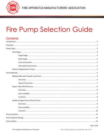
ELECTRICAL INFORMATION1. Employ a licensed electrician to perform thewiring. All wiring must be done in accordance withapplicable national and local electrical codes.2. Check that the power supply corresponds with theelectrical rating of the submersible motor and thecontrol box(if required). Make sure that the control boxelectrical rating matches the motor electrical rating.3. Every installation requires a fused disconnect switchor circuit breaker.4. Every installation must be grounded. There must bea reliable ground connection between the pump andthe distribution panel. The motor lead incorporates agreen grounding conductor.5. Lightning arrestors are recommended for everyinstallation. All stainless steel, single phase motorsthru 5HP have built-in lightning arrestors. Any 6” motoror 4”, 3-phase motor requires a separate lightningarrestor installed as close to the wellhead as possible.Install the arrestor in accordance with manufacturersrecommendations. A lightning arrestor providesprotection against induced voltage surges on6. Mount the control box in an area protected from rain,snow, direct sunlight or other high temperatures asthis may cause tripping of the overload protector.Also protect the control box from extreme cold(below 25oF/-32oC) as this may have adverse effectson starting capacitor.8. A three-wire, single-phase pump requires a motorcontrol box incorporating overload relays. Fig. 3shows a typical wiring diagram for a three-wire,single-phase installation. Note that a magneticcontactor must be used if the pressure switchelectrical rating is not sufficient to handle thesubmersible motor electrical rating. The pressureswitch would then be incorporated into a pilotcircuit to control the magnetic contactor. Makethe connections at the control box in accordancewith the wiring diagram in the control box to avoiddamage to the motor.FIGURE 3 - 3-WIRE, 1-Phase, 1/2 thru 3 HPPump Wiring DiagramPressure Switch (for pilot circuit)If Magnetic Contactor is usedfor starting.Note: Order of red, yellow and black mayvary from control box to control box.Always connect like colors.Single-PhaseControl BoxCircuit Breakeror Fused Disconnect SwitchL1 L2 R Y BRedIncoming 1 Phase PowerYellowSwitch or Timer (for direct switching) ORMagnetic Contactor (w/ pilot circuit)Black1-Phase Sumbersible Motor7. A two-wire pump does not require a motor controlbox, since all electrical components are built insidethe motor. Fig. 2 shows a typical wiring diagram fora two-wire installation.FIGURE 2 - 2 WIRE, 1-Phase, 1/2 thru 1-1/2 HPPump Wiring DiagramCircuit Breaker orFuse Disconnect SwitchSwitch or TimerSubmersible CableIncoming 1-Phase Power1-Phase Submersible Motor5
9. A three-phase pump does not require a motorcontrol box . Fig. 4 shows a typical wiring diagramfor a 3-wire, three-phase installation. A magneticcontractor with 3-leg protection having quick-tripambient compensated overload relays must beused.FIGURE 4 - 3-Wire, 3-Phase, 1-1/2 thru 50 HPPump Wiring DiagramCircuit Breaker ORFused Disconnect SwitchPressure SwitchMagnetic Contactor w/3-leg protection havingquick-trip ambientconpensated overload relaysLOW-YIELDING WELLA low-yielding well exists when the output from thepump is greater than the yield of the well. It canreduce the water level to the suction screen so thata mixture of air and water enters the pump. Pumpingmay stop since the pump cannot generate pressurewith insufficient water. In this case, the column of wateralready in the drop pipe holds the check valve closedand an airlock may develop inside the pump. Becausethe conditions ensure neither adequate lubrication ofthe pump nor proper cooling for the motor, damagecan result if power is not cut off quickly. Use one ormore of the following methods to correct and/or protectthis installation.1. Install additional length of drop pipe to place pumplower in well if possible.Incoming 3-Phase Power2. Install a Franklin Pumptec or similar electronicdrawdown sensor.3-Phase Submersible Motor10. Use an ohmeter to make continuity and insulationchecks after the installation is completed.11. Place the additional motor label with the pump labeland place both in the disconnect switch or circuitbreaker box for future reference.WELL TESTCheck the pump and well performance before makingthe final connection to the discharge system.1. Install a gate valve on the end of the pipe. Partiallyopen the valve.2. Start the pump.3. Open valve gradually to give full flow.4. If the discharge is not clear, let the pump run untilwater clears. If water does not clear in 30 minutes,stop the pump and take the necessary steps tocorrect the condition. After the water has appearedclear, check for sand by discharging into a cleanbucket or suitable container.5. Close valve until maximum required system flowrate is obtained (this should correspond to the cut-inpressure of the pressure switch). Ensure that theoutput of the pump at this setting is not greaterthan the yield of the well. This can be checked bymonitoring the well drawdown level and ensuringthat the level is stable at the maximum requiredsystem flow rate.C A U T I O N Never run pump unless it iscompletely submerged in water. If run withoutwater, the pump and motor could be damaged.Note also that air drawn into the pump can causean airlock under certain conditions.63. Install a floatless liquid level control. This deviceconsists of an electrical relay activated by currentsflowing through the ground-return circuits ofelectrodes hung in the well. The lower (STOP)electrode, just above the pump, ensures that thewater level can never be pumped down to thesuction screen. The upper (START) electrode, justbelow the lowest static water level, ensures thatthe pump can start again as soon as the well hasrecovered. A floatless liquid level control worksin series with the pressure switch. Refer to themanufacturers instructions provided with control.4. Install a flow control valve in the discharge lineupstream from the pressure switch. This restrictsthe output from the pump without affecting the ratethat water can be drawn from the pressure tank.Nevertheless, a heavy demand for water couldempty the pressure tank, so a tank with a bondeddiaphragm, air cell, or water bag is recommended.5. Install a smaller pump to avoid over pumping thewell. Have dealer size pump to the well yield.6. Install a low-pressure cut-off switch. A low pressurecut off switch, or a pressure switch with such anarrangement built in, protects a shallow-well pumpfrom losing its prime, but it does not always providesatisfactory protection to a submersible pump fromthe effects of over pumping the well. This is becauseit responds to a loss of pressure at the surface,which may occur after an air lock has formed insidethe pump. We recommend either a floatless liquidlevel control or a flow control valve, in that order,in preference to a low-pressure cutoff switch asprotection against over pumping.
DISCHARGE PLUMBINGFig. 1 illustrates a typical well installation showingabove ground components. Adhere to the followingitems when installing the discharge plumbing.1. Install an above ground check valve upstream fromthe pressure switch.2. Always install a pressure relief valve in the system.The relief valve should be capable of discharging theflow rate of the pump at the rated working pressureof the pressure tank. Locate the relief valve close tothe pressure tank.3. Install a pressure switch between the check valveand the pressure tank. Refer to Fig. 2, 3, or 4 forproper wiring connections of pressure switch.4. Install a pressure tank as close as possible tothe pressure switch. Refer to manufacturer’srecommendations for installation.TROUBLESHOOTING1. PUMP FAILS TO STARTa) Electrical trouble - call dealer or electrician.b) Drawdown protection device has pump turned off.c) Overload tripped.d) Reset low pressure cutoff switch (if installed).2. PUMP FAILS TO DELIVER WATERa) Air lock in pump.b) Clogged intake screen.c) Insufficient well yield.3. PUMP GIVES REDUCED OUTPUTa) Insufficient well yield.b) Worn pump.c) Clogged intake screen.d) Low voltage.e) Incorrect rotation (3-phase only).4. PUMP CYCLES TOO FREQUENTLYa) Excessive pressure drop between pressure switchand pressure tank.b) “Cut-in” pressure at pressure tank too high.c) “Cut-out” pressure at pressure tank too low.d) Waterlogged pressure tank.e) Start and stop electrodes of floatless liquid levelcontrol set too close together.f) Tank sized too small to meet system requirements.5. OVERLOADS TRIPa) Electrical trouble - call dealer or electrician.6. PRESSURE SWITCH CYCLES RAPIDLY WHENPUMP STARTSa) Pressure switch too far from pressure tank.b) Adjust air charge of tank to manufacturer’srecommendations.7
BOMBAS SUMERGIBLESDE 4” y 6” (10 y 15 cm)MANUAL DEL PROPIETARIO DELEA Y ACATE LAS INSTRUCCIONESDE SEGURIDADÉste es el símbolo de alerta de seguridad. Cuandovea este símbolo en la bomba o en el manual, busqueuna de las siguientes palabras indicadoras y esté atento alpeligro potencial de lesiones:P E L I G R O advierte sobre peligros que, de ignorarse,causarán lesiones graves, letales o daños materialesimportantes.ADVERTENCIA advierte sobre peligros que, de ignorarse,pueden causar lesiones graves, letales o daños materialesimportantes.PRECAUCIÓN advierte sobre peligros que, de ignorarse,causarán o pueden causar lesiones leves o dañosmateriales importantes.La etiqueta AVISO indica instrucciones especiales que sonimportantes, pero que no están relacionadas con peligros.Lea y acate cuidadosamenteADVERTENCIA todas las instrucciones deseguridad indicadas en estemanual o en la bomba.Mantenga las etiquetas deseguridad en buen estado.ANTES DE INSTALAR ESTA BOMBA CERCIÓRESEDE LEER MINUCIOSAMENTE ESTE MANUAL DELPROPIETARIO.PRECAUCIÓN Para evitar dañar la bomba, llénela conagua antes de ponerla en marcha. El motor de estabomba está garantizado por el fabricante y en casode fallas debe devolverse a una estación de servicioautorizada para su reparación. La garantía del motorse anulará si las reparaciones son efectuadas por unaestación de servicio no autorizada.INSPECCIONE EL EMBARQUETras recibirla, examine la bomba para cerciorarse de queno se haya dañado durante el envío. En caso de detectaralgún daño evidente, informe inmediatamente al distribuidora quien adquirió la bomba. Revise el embalaje de la bombapara cerciorarse de que incluya la bomba, el motor y suscables (si la bomba que compró incluye un motor).Voltaje peligroso. Puedecausar descargas,quemaduras o lamuerte.Ponga a tierra la bombaantes de conectarla alsuministro eléctrico.Desconecte el suministroeléctrico antes detrabajar en la bomba, elmotor o el tanque.Reemplace las etiquetas faltanteso estropeadas.ADVERTENCIA Cablee elmotor según el voltajecorrecto. En la secciónsobre el sistema eléctricode este manual y en laplaca identificatoria delmotor encontrará másinformación al respecto.ADVERTENCIA Ponga a tierra el motor antes de conectarlo alsuministro eléctrico.ADVERTENCIA Cumpla los requisitos del Código EléctricoNacional, el Código Eléctrico Canadiense y los códigoslocales para todo el cableado.ADVERTENCIA Siga las instrucciones de cableado que seindican en este manual cuando conecte el motor a las líneaseléctricas.
ADVERTENCIA¡INFORMACIÓN IMPORTANTE PARA LOSINSTALADORES DE ESTE EQUIPO!ESTE EQUIPO DEBE SER INSTALADO POR PERSONALTÉCNICAMENTE CALIFICADO. SI NO SE INSTALAACATANDO LOS CÓDIGOS ELÉCTRICOS NACIONALESY LOCALES, Y LAS RECOMENDACIONES DEFRANKLIN ELECTRIC, PUEDE CAUSAR DESCARGAELÉCTRICA O PELIGRO DE INCENDIO, RENDIMIENTOINSATISFACTORIO Y FALLA DEL EQUIPO. LAINFORMACIÓN DE INSTALACIÓN PUEDE SOLICITARSEA LOS FABRICANTES Y DISTRIBUIDORES DE LABOMBA, Y DIRECTAMENTE A FRANKLIN ELECTRIC.LLAME A FRANKLIN SIN COSTO AL 800-348-2420 PARAOBTENER MÁS INFORMACIÓN. CONSERVE ESTA HOJAINFORMATIVA CON EL EQUIPO PARA REFERENCIAFUTURA.ANTECEDENTES DE INSTALACIÓNEs aconsejable mantener un registro preciso de suinstalación. Cerciórese de anotar los datos siguientes:Adquirido en:Fecha de instalación:No. de modelo de la bomba*Código de fecha de la bomba*Diá. interno del pozo (pulg/mm):Profundidad del pozo (pies/m):Profundidad del agua (pies/m):Ubicación de la bomba (pies/m):Tamaño de la cañería de bajada:Calibre del alambre (bomba a caja de control):Calibre del alambre (caja de control a suministro):Distancia horizontal (entre el pozo y la casa):Marca del motor*AmpsADVERTENCIASE PUEDE PRODUCIR UNA DESCARGA ELÉCTRICAGRAVE O LETAL SI EL MOTOR, LA CAJA DE CONTROL,LA PLOMERÍA METÁLICA Y OTROS METALESCERCANOS AL MOTOR O CABLE, SE CONECTANINCORRECTAMENTE AL TERMINAL DE PUESTA ATIERRA DEL SUMINISTRO ELÉCTRICO USANDO UNALAMBRE DE CALIBRE INFERIOR A LOS DEL MOTOR.PARA REDUCIR EL RIESGO DE DESCARGA ELÉCTRICA,DESCONECTE EL SUMINISTRO ANTES DE EFECTUARTRABAJOS EN O CERCA DEL SISTEMA DE AGUA. NOUSE EL MOTOR EN ZONAS DE NATACIÓN.HPVoltiosFaseMarca de la caja de controlHPVoltiosSuministro eléctricoVoltiosHZPresostato (lb/pulg2)ArranqueCorte* Esta información aparece en el rótulo de la bomba odel motor. Nos permitirá identificar la bomba en caso deaveriguaciones posteriores.PRUEBE EL FUNCIONAMIENTOSi antes de la instalación va a probar el funcionamiento de labomba:1. Cerciórese de que el suministro eléctrico correspondacon el que aparece en la placa identificatoria del motor yla caja de control. (si se requiere).2. Instale la bomba y los componentes apropiados para laprueba tal como se muestra en la Fig. 1.3. Cerciórese de que el suministro eléctrico esté apagado yel cortacircuito o interruptor de desconexión esté abierto.Haga las conexiones eléctricas apropiadas en el motor talcomo se muestra en la Fig. 2, 3 ó 4.104. UNIDAD TRIFÁSICA - Un motor trifásico requiere unarrancador magnético equipado con calentadores decompensación ambiental de disparo rápido y tamaño correctopara la potencia del motor. Para garantizar el giro correcto delas unidades trifásicas, afiance firmemente el armazón dela bomba y energícelo momentáneamente encendiendo yapagando rápidamente el conmutador de línea. Si el giro escorrecto, el armazón reaccionará en sentido horario al mirarsedesde la descarga de la bomba (es decir, el eje de la bombagirará en sentido antihorario). Para invertir el giro intercambiecualquiera de los dos cables en el arrancador magnético.
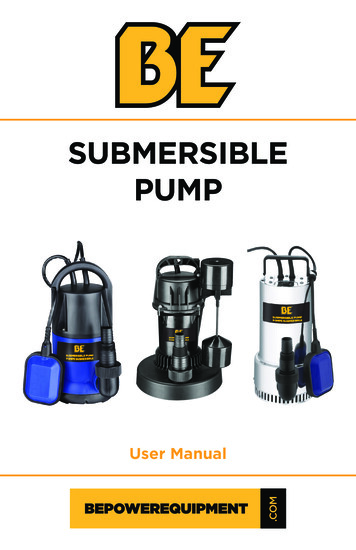
5. Haga funcionar la bomba y el motor unos cuantossegundos para verificar que estén en buen estado.Tanque de presiónFIGURA 1 - Diagrama de instalaciónVea los diagramas de cableadoPresostatoSello sanitario parapozos o adaptadorsin fondoVálvula decompuertaVálvula deretención a resorteCañería de descargaCable sumergibleVálvula de alivio de presiónCañería de servicioManómetroVálvula de retencióna resorte(recomendada cada 100’/30 m)Cable de seguridadCañeríade bajadaCable(afianzado a la cañería debajada con cinta o abrazaderascada 10’/3 m)2. Mecanismo antitorsión justo arriba de la bomba para noescoriar el cable cuando la bomba y la cañería giren duranteel ciclo de arranque y parada. (Consulte la Figura 1)Cerciórese de mantener las cañerías limpias y libres deguijarros, escamas y virutas de roscas. Conecte todos losherrajes en forma segura y hermética. Se recomienda usarsellante de cañerías.VÁLVULAS DE RETENCIÓNMecanismo antitorsiónCaja del pozoVálvula de retencióna resorte en la descargade la bombaUnidad debomba sumergibleATENCIÓN: SE RECOMIENDA USAR CABLE DE ACERO PARAASEGURAR LA BOMBA. UN CABLE DE ACERO TRENZADO DE3/16” A 1/4” DE DIÁMETRO ES SUFICIENTE PARA SOPORTARLA MAYORÍA DE LOS ENSAMBLES BOMBAS/MOTOR. SIEMPREES MEJOR CONFIRMAR QUE EL ENSAMBLES BOMBAS/MOTOR. NO EXCEDE EL LÍMITE MÁXIMO DE PESO PARA ELCABLE SELECCIONADO.Nota: Mantenga la bomba por lo menos a5’ (1.5 m) del fondo del pozo y sobre el filtrode éste o las perforaciones de la caja.Filtro de succiónMotorFiltro del pozo operforaciones de la cajaIDONEIDAD DEL POZOInstale la bomba sólo en un pozo que haya sidocorrectamente construido. El agua proveniente de un pozomal construido suele contener una cantidad excesiva dearena y agentes abrasivos que pueden dañar la bomba.Cerciórese de que el pozo sea lo suficientemente grandepara que permita instalar la bomba en la profundidadrequerida. No instale la bomba debajo de las perforacionesde la caja ni del filtro del pozo, a menos que haga los ajustesnecesarios para garantizar un flujo de agua adecuado sobreel motor para fines de enfriamiento. Determine la ubicacióncorrecta de la bomba conforme los antecedentes que leproporcione el perforista, considerando el nivel estáticodel agua y el descenso del nivel según la tasa de bombeopropuesta. Mantenga la bomba por lo menos a cinco pies(1.5 m) del fondo del pozo perforado.EMPALME DEL CABLE DE ALIMENTACIÓNSiga las instrucciones que vienen adjuntas en el juego deempalme del cable que adquirió.CAÑERÍA DE BAJADASe recomienda la bajada de cañería durante lasuspensión de las bombas en el pozo. Favor de seguir lasrecomendaciones del fabricante a cerca de profundidad ypresión. Preste especial atención a:1. Un cable de seguridad para evitar la pérdida de la bombasi la cañería se rompe.Se recomienda usar una o más válvulas en instalaciones debombas sumergibles. Si la bomba no tiene una válvula checkincluida, ésta debe instalarse en la línea de descarga sinsobrepasar los 25 pies de distancia de la bomba. Para ajustesmás profundos, las válvulas check deben de ser instaladasbajo las recomendaciones del fabricante. Frecuentemente senecesita más de una válvula check, sin embargo, no se debede sobrepasar el número recomendado de válvulas check.Válvulas check de tipo columpio no son aceptadas y nuncadeberán ser usadas con motores/bombas sumergibles. Lasválvulas tipo columpio tienen un tiempo de reacción más lentoy puede causar un golpe de ariete (ver en siguiente página).Válvulas check internas o en la tubería cierran rápido, lo queevita el golpe de ariete.NOTA: Sólo
always be used in submersible pump installations. If the pump does not have a built-in check valve, an inline check valve should be installed in the discharge line within 25 feet of the pump and below the draw down level of the water supply. For deeper settings, check valves should be installed per the manufacturer's recommendations.