Transcription
Plotter KitCatalog Numbers 1492-PLTKITUser Manual
Important User InformationBecause of the variety of uses for the products described in this publication, those responsible for the application and use of this controlequipment must satisfy themselves that all necessary steps have been taken to assure that each application and use meets all performanceand safety requirements, including any applicable laws, regulations, codes and standards.The illustrations, charts, sample programs and layout examples shown in this guide are intended solely for purposes of example. Since thereare many variables and requirements associated with any particular installation, Allen-Bradley does not assume responsibility or liability (toinclude intellectual property liability) for actual use based upon the examples shown in this publication.Allen-Bradley publication SGI-1.1, Safety Guidelines for the Application, Installation and Maintenance of Solid-State Control (available fromyour local Allen-Bradley office), describes some important differences between solid-state equipment and electromechanical devices thatshould be taken into consideration when applying products such as those described in this publication.Reproduction of the contents of this copyrighted publication, in whole or part, without written permission of Rockwell Automation, isprohibited.Throughout this manual we use notes to make you aware of safety considerations:ATTENTION: Identifies information about practices orcircumstances that can lead to personal injury or death, propertydamage or economic lossAttention statements help you to: identify a hazard avoid a hazard recognize the consequencesIMPORTANTIdentifies information that is critical for successfulapplication and understanding of the product.Allen-Bradley is a trademark of Rockwell Automation. Windows is a trademark of the Microsoft Corporation.
Table of ContentsPrefaceOverview of this Manual . . . . . . . . . . . . . . . . . . . . . . . . . . . . . . . . . . . . . iIntended Audience . . . . . . . . . . . . . . . . . . . . . . . . . . . . . . . . . . . . . . . . . . iiConventions . . . . . . . . . . . . . . . . . . . . . . . . . . . . . . . . . . . . . . . . . . . . . . . iiCh. 1—Marking SystemDescriptionChapter Objectives. . . . . . . . . . . . . . . . . . . . . . . . . . . . . . . . . . . . . . . .Marking System Components . . . . . . . . . . . . . . . . . . . . . . . . . . . . . . .Marker Cards . . . . . . . . . . . . . . . . . . . . . . . . . . . . . . . . . . . . . . . . . . . .Marker Types . . . . . . . . . . . . . . . . . . . . . . . . . . . . . . . . . . . . . . . . . . . .ClearTools Software. . . . . . . . . . . . . . . . . . . . . . . . . . . . . . . . . . . . . . .Accessories . . . . . . . . . . . . . . . . . . . . . . . . . . . . . . . . . . . . . . . . . . . . . .Ch. 2 — Initial SetupChapter Objectives. . . . . . . . . . . . . . . . . . . . . . . . . . . . . . . . . . . . . . . . 2-1Setup . . . . . . . . . . . . . . . . . . . . . . . . . . . . . . . . . . . . . . . . . . . . . . . . . . . 2-1Location . . . . . . . . . . . . . . . . . . . . . . . . . . . . . . . . . . . . . . . . . . . . . 2-1Connections . . . . . . . . . . . . . . . . . . . . . . . . . . . . . . . . . . . . . . . . . . 2-1Installing the Plotter Driver . . . . . . . . . . . . . . . . . . . . . . . . . . . . . . . . . 2-2Installing the driver for the plotter 1492-PLTKIT Series E within:Windows 2000 . . . . . . . . . . . . . . . . . . . . . . . . . . . . . . . . . . . . . . . . . . . 2-2Windows Vista . . . . . . . . . . . . . . . . . . . . . . . . . . . . . . . . . . . . . . . . . . . 2-6Windows XP. . . . . . . . . . . . . . . . . . . . . . . . . . . . . . . . . . . . . . . . . . . . 2-12Windows 7 . . . . . . . . . . . . . . . . . . . . . . . . . . . . . . . . . . . . . . . . . . . . . 2-14Installing a Pen in the Pen Station. . . . . . . . . . . . . . . . . . . . . . . . . . . 2-19Removing a Pen from the Pen Station . . . . . . . . . . . . . . . . . . . . 2-19Plotting with the 1492-PLOTADPT. . . . . . . . . . . . . . . . . . . . . . . . . 2-20Activating the Plotter with ClearTools . . . . . . . . . . . . . . . . . . . . . . . 2-20Introduction . . . . . . . . . . . . . . . . . . . . . . . . . . . . . . . . . . . . . . . . . 2-20Switching to Plot Mode . . . . . . . . . . . . . . . . . . . . . . . . . . . . . . . . 2-20Startup options for Plot Mode . . . . . . . . . . . . . . . . . . . . . . . . . . 2-21Mapping to Plotter: . . . . . . . . . . . . . . . . . . . . . . . . . . . . . . . . . . . . . . 2-22Adjusting Marker Type . . . . . . . . . . . . . . . . . . . . . . . . . . . . . . . . . . . 2-25Plotting Multiple Cards . . . . . . . . . . . . . . . . . . . . . . . . . . . . . . . . 2-27Operation of Plotter— 3Chapter Objectives. . . . . . . . . . . . . . . . . . . . . . . . . . . . . . . . . . . . . . . .Operation . . . . . . . . . . . . . . . . . . . . . . . . . . . . . . . . . . . . . . . . . . . . . . .ON/OFF Buttons . . . . . . . . . . . . . . . . . . . . . . . . . . . . . . . . . . . . .Clear Buffer . . . . . . . . . . . . . . . . . . . . . . . . . . . . . . . . . . . . . . . . . .Pen Station Open/Close Button. . . . . . . . . . . . . . . . . . . . . . . . . .Stop/View Button . . . . . . . . . . . . . . . . . . . . . . . . . . . . . . . . . . . . .Cursor and Pen Up/Down Buttons . . . . . . . . . . . . . . . . . . . . . . .i1-11-11-21-31-61-73-13-13-13-13-23-23-3
Table of ContentsiiTroubleshooting andMaintenance—4Appendix AChapter Objectives. . . . . . . . . . . . . . . . . . . . . . . . . . . . . . . . . . . . . . . . 4-1Using the Troubleshooting Chart . . . . . . . . . . . . . . . . . . . . . . . . . . . . 4-1Required Equipment . . . . . . . . . . . . . . . . . . . . . . . . . . . . . . . . . . . . . . 4-1Plotter Maintenance . . . . . . . . . . . . . . . . . . . . . . . . . . . . . . . . . . . . . . . 4-2Cleaning Plotter . . . . . . . . . . . . . . . . . . . . . . . . . . . . . . . . . . . . . . . 4-2Removing Sealing Unit from Pen Station. . . . . . . . . . . . . . . . . . . 4-2Inserting and Adjusting Sealing Unit . . . . . . . . . . . . . . . . . . . . . . 4-2Exchanging Priming Plates (for starting plotter pen). . . . . . . . . . 4-3Pen Maintenance . . . . . . . . . . . . . . . . . . . . . . . . . . . . . . . . . . . . . . . . . 4-3Technical Specifications. . . . . . . . . . . . . . . . . . . . . . . . . . . . . . . . . . . . 4-4For Plotter Plates with Adhesive Strips, 1492-PLOTPLT,Series A . . . . . . . . . . . . . . . . . . . . . . . . . . . . . . . . . . . . . . . . . . . . . . . . A-1Adhesive Strip Preparation . . . . . . . . . . . . . . . . . . . . . . . . . . . . . . . . A-1
PrefaceOverview of this ManualThis manual describes how to use components of the Allen–Bradley Plotter Kitto create and print markers for Bulletin 1492 Terminal Blocks and accessories.The following table describes the contents of this manual. ChapterTitleContentsPrefaceProvides an overview of the manual.1Marking System DescriptionProvides a brief overview of the hardwareand software. Includes a description ofsystem accessories.3Operation of PlotterDescribes plotter controls.2Initial SetupDescribes initial plotter setup.4Troubleshooting andMaintenanceProvides assistance in identifying andcorrecting common operating problems.Procedures for routine maintenance itemsare also provided.Note: Refer to the ClearTools Software Manual for software installationand setup.At the end of its life, this equipment should becollected separately from any unsorted municipal wastei
PrefaceIntended AudienceBasic knowledge of the Microsoft Windows Operating System is required tooperate the 1492-PLTKIT Plotter System. For ClearTools software instructions,refer to the user’s manual contained within the ClearTools software.ConventionsThis manual uses the following conventions:· Allen–Bradley Marking System software is referred to as ClearTools.· Marker refers to the individual tabs that snap onto a terminal block.Terminal BlockMarker· A marker card is a set of multiple markers. See Table 1.A for moreinformation on marker cards.OneBranchOneMarkerCardiiOneMarker
Chapter1Marking System DescriptionChapter ObjectivesThis chapter describes: Marking System components Marker Cards Marker types AccessoriesMarking SystemComponentsThe Terminal Block Marking System kit (Catalog No. 1492–PLTKIT)includes: Allen–Bradley Marking System (ClearTools) Software Plotter Base Plate* Stainless-Steel Inlay (5) Disposable Pen USB Cable (connects personal computer to plotter) Power Cable Plotter User Manual (this document) 220V AdapterIn addition, you need: Personal computer Marker Cards (See Table 1.A)InlayClearToolsSoftwareBase PlatePlotterPersonal Computer* A special plate, 1492-PLOTPLTA, is needed for the following markers: 1492-MW5-21, 1492-MW6-21,1492-MW7-21).
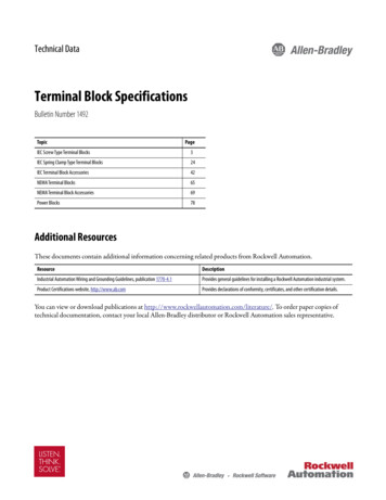
Marking System DescriptionAllen–Bradley markers can be printed in either a horizontal or verticaldirection. The ClearTools software displays a view of the markers as theywould appear on the plotter.Marker CardsGNDTB1TB2TBPlotting startshereVerticalUpside-DownDirectionGND TB1 TB2 TB1-2TBTB2TB1GNDHorizontalUpside-DownDirectionGND TB1 TB2 TBVertical DirectionHorizontal DirectionPlotting always starts in the upper left corner of the marker card.The plotter base plate has spaces for 5 marker cards. Spaces are numbered 1 to5, from left to right.InlayWritingArmPen Station12345BasePlatePlotterControlPanelThe inlay may be installed in the base plate at different heights by lining up thenumber (1 to 5) of the inlay with the red locating rib of a given space.
Marking System DescriptionMarker Types1-3The marking system supports a variety of marker types.Table 1.AAllen–Bradley Markers for Allen-Bradley ProductsMarker/LabelCatalog No.Use With These Allen-Bradley Terminal Blocks and OtherProducts1492-M3X121492-L2, 1492-L2T, 1492-L2Q,1492-LD2, 1492-LD2C, 1492-LG2,1492-LG2T, 1492-LG2Q, 1492-LDG2, 1492-LDG2C1492-M3X51492-L2, 1492-L2T, 1492-L2Q, 1492-LD2, 1492-LD2C, 1492-LG2,1492-LG2T, 1492-LG2Q, 1492-LDG2, 1492-LDG2C, 1738-OB16EM12,1738-OB16E25DS, 1738-OB16E19M23, 1738-IB16DM121492–M5X51492-CPL, 1492-FPK2 , 1492-J3, 1492-J10, 1492-J16, 1492-J35,1492-J50, 1492-J70, 1492-JD3, 1492-J2Q, 1492-J3TW, 1492-JD3C,1492-J3F, 1492-JD3F, 1492-JG2Q, 1492-JG3, 1492-JG3TW,1492-JDG3, 1492-JDG3C, 1492-JKD3, 1492-JKD3TP, 1492-J3P,1492-J3PTP, 1492-JD3P, 1492-JD3PTP, 1492-JD3PSS, 1492-JD3PSSTP,1492-JDG3P, 1492-JDG3PTP, 1492-JDG3PSS, 1492-JDG3PSSTP,1492-JD3DF*, 1492-JD3DR*, 1492-JD3RB*, 1492-JD3RC001,1492-JD3SS, 1492-JTC3*, 1492-JC3, 1492-JDC3, 1492-LMJ3,1492-LMJG3, 1492-LM3, 1492-LM3Q, 1492-LMG3, 1492-LMP3,1492-LMP3Q, 1492-L3, 1492-L3T, 1492-L3Q, 1492-LD3, 1492-L3QS,1492-LTF3, 1492-LD3C, 1492-LS2-3, 1492-LS2-3L, 1492-LSG2-3,1492-LS2-4, 1492-LS2-4L, 1492-LSG2-4, 1492-LG3, 1492-LG3T,1492-LG3Q, 1492-LDG3, 1492-LDG3C, 1492-LKD3, 1492-L3P,1492-LDG3P,1492-LDAG3, 1492-LC3, 1492-LCDC3, 1492-FB* FuseBlocks1492–M5X81492-JD3, 1492-JD3C, 1492-JD3F, 1492-JDG3, 1492-JDG3C,1492-JD3DF*, 1492-JD3DR*, 1492-JD3RB*, 1492-JD3RC001,1492-JD3SS1492–M5X101492-ERL35, 1492-LM3Q, 1492-LMG3, 1492-LMJ3, 1492-LMJG3,1492-LMP3, 1492-LMP3Q, 1492-L3, 1492-L3T, 1492-L3Q, 1492-LD3,1492-L3QS, 1492-LD3C, 1492-LG3, 1492-LG3T, 1492-LG3Q,1492-LDG3, 1492-LDG3C, 1492-LKD3, 1492-L3P, 1492-LC3,1492-LDC3, Bulletin 931 Signal Conditioners, 1492-JD3P,1492-LM3, 1492-LDG3P, 1492-LDAG31492–M5X121492-J3F, 1492-JG2Q, 1492-JG3, 1492-JG3TW, 1492-JKD3,1492-JKD3TP, 1492-J3P, 1492-J3PTP, 1492-JTC3*, 1492-JC3,1492-JDC3, 1492-J3, 1492-J2Q, 1492-J3TW1492-M5X151492-ERL15, 1492-LMP3Q1492-M5X301492-WGB51492-M6X51492-EAJ15, 1492-J4, 1492-JG4, 1492-L4, 1492-L4T, 1492-L4Q,1492-LD4, 1492-LD4C, 1492-LG4, 1492-LG4T, 1492-LG4Q, 1492-LDG4,1492-LDG4C, 1492-LD4DF, 1492-LD4DR, 1492-LD4RB*, 1492-LD4SS,1492-J4M1492-M6X101492-L4, 1492-L4T, 1492-L4Q, 1492-LD4, 1492-LD4C, 1492-LG4,1492-LG4T, 1492-LG4Q, 1492-LDG4, 1492-LDG4C, 1492-LD4DF,1492-LD4DR, 1492-LD4RB*, 1492-LD4SS, Bulletin 931 SignalCondioners1492-M6X121492-J4, 1492-JG4, 1492-J4M, 1492-L6, 1492-L6T, 1492-L10,1492-LG6, 1492-LG6T, 1492-LG10, 1492-EAJ35
1-4Marking System DescriptionTable 1.AAllen–Bradley Markers for Allen-Bradley ProductsMarker/LabelCatalog No.Use With These Allen-Bradley Terminal Blocks and OtherProducts1492-M7X121492-EAJ35, 1492-EAHJ35, 1492-H4, 1492-H5, 1492-H6, 1492-H7,1492-J6, 1492-J10, 1492-J16, 1492-J35, 1492-J50, 1492-J70,1492-J120, 1492-JG6, 1492-JG10, 1492-JG16, 1492-JG35,1492-JG50, 1492-JG70, 1492-JG120, 1492-L16, 1492-L16D, 1492-L35,1492-LG16, 1492-LG351492-M8X51492-J6, 1492-J10, 1492-J16,1492-J35,1492-J50,1492-J70,1492-JG6, 1492-JG10, 1492-JG16, 1492-JG35, 1492-JG50,1492-JG70, 1492-L6, 1492-L6T, 1492-L10, 1492-L16, 1492-L16D,1492-L35, 1492-LG6, 1492-LG6T, 1492-LG10, 1492-LG16, 1492-LG351492-MR5X81492-J3, 1492-JD3, 1492-JD3C, 1492-JD3F, 1492-JDG3,1492-JDG3C, 1492-JD3DF*, 1492-JD3DR*, 1492-JD3RB*,1492-JD3RC001, 1492-JD3SS, 1492-L31492-MR6X81492-J4, 1492-J4M, 1492JG4, 1492-L4T, 1492-L4Q, 1492-LD41492-LD4C, 1492-LG4, 1492-LG4T, 1492-LG4Q, 1492-LDG4,1492-LDG4C, 1492-LD4DF, 1492-LD4DR, 1492-LD4RB*,1492-LD4SS, 1492-L6, 1492-L6T, 1492-L10, 1492-LG6, 1492-LG6T,1492-LG10, 1492-EAJ351492–MR5X101492-ERL35, 1492-LM3Q, 1492-LMG3, 1492-LMJ3, 1492-LMJG3,1492-LMP3, 1492-LMP3Q, 1492-L3, 1492-L3T, 1492-L3Q, 1492-LD3,1492-L3QS, 1492-LD3C, 1492-LG3, 1492-LG3T, 1492-LG3Q,1492-LDG3, 1492-LDG3C, 1492-LKD3, 1492-L3P, 1492-LC3,1492-LDC3, Bulletin 931 Signal Conditioners, 1492-JD3P,1492-LM3, 1492-LDG3P, 1492-LDAG31492-MR5X121492-J2Q, 1492-J3, 1492-J3TW, 1492-J3F, 1492-JG2Q, 1492-JG3,1492-JG3TW, 1492-JKD3, 1492-JKD3TP, 1492-J3P, 1492-J3PTP,1492-JTC3*, 1492-JC3, 1492-JDC31492-MR6X121492-J4, 1492-JG4, 1492-J4M,1492-L6T, 1492-L10, 1492-LG6,1492-LG6T, 1492-LG101492-MR8X121492-J6, 1492-J10, 1492-J16, 1492-J35, 1492-J50, 1492-J70,1492-J120, 1492-J240, 1492-JG10, 1492-JG16, 1492-JG35,1492-JG50, 1492-JG70, 1492-JG120,1492-L6, 1492-L6T, 1492-L10,1492-L16, 1492-L16D, 1492-L35, 1492-LG6, 1492-LG6T, 1492-LG10,1492-LG16, 1492-LG351492-MC4X5Some terminal blocks from Murr and Phoenix Contact1492-MC5X5Some terminal blocks from Murr and Phoenix Contact1492-MC6X51492-FB* fuse blocks, some terminal blocks from Murr and PhoenixContact1492-MC7X5Some terminal blocks from Phoenix Contact1492-MC5X4Some terminal blocks from Phoenix Contact1492-MC5X8Some terminal blocks from Entrelec, Phoenix Contact, Telemecanique,Wieland1492-MC5X10Some terminal blocks from Entrelec, Phoenix Contact, Telemecanique,Wieland1492-MC5X12Some terminal blocks from Entrelec, Phoenix Contact, Telemecanique,Wieland
Marking System Description1-5Table 1.AAllen–Bradley Markers for Allen-Bradley ProductsMarker/LabelCatalog No.Use With These Allen-Bradley Terminal Blocks and OtherProducts1492-MC6X10Bulletin 700-HL relays, Some terminal blocks from Entrelec, PhoenixContact, Telemecanique, Wieland1492-MC8X10Bulletin 700-HL relays, Some terminal blocks from Entrelec, PhoenixContact, Telemecanique, Wago, Wieland1492-MCS7X10Some terminal blocks from Siemens1492-MCS5X10Some terminal blocks from Siemens1492-MCS6X10Some terminal blocks from Siemens1492-MCS7X7Some terminal blocks from Siemens1492-MCS5X8Some terminal blocks from Siemens1492-MCS6X8Some terminal blocks from Siemens1492-MCW4X9Some terminal blocks from Murr and Wago1492-MCW5X9Some terminal blocks from Murr and Wago1492-MCW5X9FSome terminal blocks from Murr and Wago1492-MCW5X5Some terminal blocks from Murr and Wago1492-MCW6X9Some terminal blocks from Murr and Wago1492-MH5X101492-L3, 1492-L3T, 1492-L3Q, 1492-L3QS, 1492-LG3, 1492-LG3T,1492-LG3Q, 1492-LC3, 1492-LMJ3, 1492-LMJG3, 1492-LM3Q,1492-LMG3, 1492-LMP3, 1492-LMP3Q1492-MH5X151492-L3,1492-L3T, 1492-L3Q 1492-L10, 1492-L16, 1492-L16D,1492-L35, 1492-LG3, 1492-LG3T, 1492-LG3Q, 1492-LG10, 1492-LG16,1492-LG351492-MH6X121492-L4, 1492-L4T, 1492-L4Q, 1492-L6, 1492-L6T, 1492-LG4,1492-LG4T, 1492-LG4Q, 1492-LG6, 1492-LG6T1492-MN811492-HM1, 1492-HM2, 1492-HM3, 1492-CB*1492-MN831492-CB*, 1492-HM31492-MAS9X17Any equipment (self-adhesive)1492-MAS6X15Bulletin 700 relays, any equipment (self-adhesive)1492-MAS9X111760-Pico, any equipment (self-adhesive)1492-MS5X51492-WM3, 1492-WMD11492-MS5X91492-WR3, 1492-WTF3*, 1492-WTS3*, 700-HA, Bulletin 800Fcontact blocks1492-MS5X121492-W3, 700-HA1492-MS6X91492-RFB4*, 1492-RAFB4*, 1492-WM4, 1492-WMG4, 1492-W4TW,700-HA1492-MS6X121492-W4, 1492-W6, 1492-W10 1492-W16S, 1492-WG4, 1492-WG6,1492-WG10S, 1492-WG16S, 700-HA1492-MS8X9700-HA, 1492-H4, 1492-H5, 1492-H6, 1492-H7, 1492-WFB4*
1-6Marking System DescriptionTable 1.AAllen–Bradley Markers for Allen-Bradley ProductsMarker/LabelCatalog No.Use With These Allen-Bradley Terminal Blocks and OtherProducts1492-MS8X121492-H4, 1492-H5, 1492-H6, 1492-H7, 1492-RFB4*, 1492-RAFB4*,1492-W10, 1492-WFB4*, 700-HA, 1492-W165, 1492-WG10,1492-WG1651492-MS8X17700-HN204, 700-HN2051492-MS9X201667 PanelConnect1492-MS10X17100-C, 100-D, 700-CF, 140, 193-E1, 193-E3, 1492-REC*1492-MW9X24Wire/cable from 6 AWG (from 16.0 mm2)1492-MW10X23Wire/cable from 6 AWG (from 16.0 mm2)1492-MW14X23Wire/cable from 6 AWG (from 16.0 mm2)1492-MW11X60Wire/cable from 6 AWG (from 16.0 mm2)1492-MW5-21#12 10 AWG (4.0 6.0 mm2) wire1492-MW6-21#10 8 AWG (6.0 10.0 mm2) wire1492-MW7-21#8 6 AWG (10.0 16.0 mm2) wire1492-MWC1-21#20 18 AWG (0.5 1.0 mm2) wire1492-MWC3-21#18 14 AWG (0.75 2.5 mm2) wire1492-MWC4-21#12 AWG (2.5 4.0 mm2) wire1492-MWC1-12#20.18 AWG (0.5 1.0 mm2) wire1492-MWC3-12#18 14 AWG (0.75 2.5 mm2) wire1492-MWC4-12#12 AWG (2.5 4.0 mm2) wire1492-SM5X101492-JD3P, 1492-JD3PTP, 1492-JD3PSS, 1492-JD3PSSTP,1492-JDG3P, 1492-JDG3PTP, 1492-JDG3PSS, 1492-JDG3PSSTP1492-M5X301492-GMC1492-MD6X91732 I/O➊ Catalog numbers in bold indicate the preferred marker.➋ Catalog numbers in italics indicate the corner markers of a spring-clamp terminal block.➌ Many bulletin number 1492-M markers have identical mounting feet, resulting in the ability to usemany different types of markers in a given product.ClearTools SoftwareClearTools software is a Microsoft Windows-based program that creates filescontaining marker card layouts. These files contain all the information to printmultiple base plates full of marker cards. See Table 1.B lists the availablemarking system accessories.
Marking System DescriptionAccessories1-7Table 1.B AccessoriesItemCatalog No.DescriptionDisposable Pen1492–PLOTPEN25Disposable ink pen with 0.25mm tipDisposable Pen1492–PLOTPEN35Disposable ink pen with 0.35mm tipPen Adapter1492-PLOTADPTPen adapter for use with Sharpie Ultra Fine Point Pen ➊Pen Station Service Kit ➋ 1492–PLOTSERVPen Station Service Kit forreplacing pen priming tabs andink-coated pen sealing unitsBase PlateBase plate for the plotterPlotter Software ➋Single Plate1492-PLOTPLT—1492-PLOTPLTACD of ClearTools SoftwareSingle plate used with wiremarkers (not included in plotter kit)➊ Recommended when plotting 12-point font or larger.➋ The latest software can be downloaded at: www.ab.com/industrialcontrols/products. SelectConnection Devices Terminal Blocks Marking Solutions X-Y Plotter Marking System SoftwareIMPORTANTIt is important to only use the above accessories with theplotter. Use of other accessories may damage the plotter.
1-8Marking System DescriptionTable 1.C Inlay Spacer SettingsMarker CardInlay Position -MCW5X94
Marking System DescriptionTable 1.C Inlay Spacer SettingsMarker CardInlay Position 2111492-SM5X1021492-SM6X1021492-MD6X931-9
1-10Marking System Description1. Line up the number on the inlay with the notched locator on the baseplate.2. Slide right side of marker card under ledge on plotter plate.3. Line-up first notch on the left side of the marker card to the notch onthe plotter plate.4. Press the left side on the marker card down on to the plotter plates. Forplotter plates with the adhesive strip, refer to Adhesive Strip Preparationon page A-1.Installing Inlay onto PlateInstalling Marker Card onto PlateTable 1.D Inlay Spacer Requirement Using Special Plate, 1492-PLOTPLTAMarker CardInlay1492-MW5-21Inlay needed1492-MW6-21No inlay needed1492-MW7-21No inlay needed
Chapter2Initial SetupChapter ObjectivesThis chapter shows how to: Set up the Plotter Installing the Plotter Driver Activating the Plotter with ClearToolsSetupLocationA dry, dust-free room is the ideal environment for the plotter. If possible, donot install the device in damp or very dusty areas. Do not expose the system todirect sunlight. Please ensure the connections on the right-hand side of thedevice are accessible all times. Position the plotter firmly on the work surfacewhere it is to be used, ensuring it is level. Please ensure the writing arm canmove freely and is not obstructed by other objects.Connections1. Install the power cord and plug into outlet.The plotter power supply features a variable AC input voltage of 100 to240V AC/50.60 Hz. The power connection can be replaced by way ofadapter plugs, as required.2. Connect the plotter to the computer using the USB cable. The USB portis located on the right-hand side of the plotter.
2-2Initial SetupInstalling the Plotter DriverInstalling the driver for theplotter 1492-PLTKIT Series Ewithin Windows 20001. Login into your Computer using an account with administrative rights.2. Connect the Plotter to your system and switch on the power.The “Found New Hardware Wizard” starts. Click on “Next”.3. Choose “Search for a suitable driver for my device (recommended)”and then click “Next”.
Initial Setup2-34. Choose “Specify a location” and click on “Next”.5. In the opening window, click on “Browse” and select the subfolder“W2K” in the folder “Psetup” on your installation CD. Confirm with“Open” and then with “OK”.6. Then click on “NEXT“. The installation begins now.
2-4Initial Setup7. During the installation a message appears stating “The software youare about to install does not contain a Microsoft digitalsignature ” and asks “Do you want to continue the installation?”Click on “Yes”.
Initial Setup2-58. Click on “Finish” to close the window.The driver for the connected device 1492-PLTKIT Series E is now installedand ready to use.
2-6Initial SetupInstalling the driver for the1492-PLTKIT Series E withinWindows Vista1. Login into your Computer using an account with administrative rights.Before you begin installing the driver you need to know if you are running the32-bit or the 64-bit version of Windows Vista on your computer. If you are notsure, you can open the following window:Start Control Panel System and Maintenance Systemor Start Control Panel System (when using the classical view of thecontrol panel).Within the line “System type” you can find the information needed.
Initial Setup2-72. Go to “Start Control Panel Printers”. Then connect your 1492-PLTKITSeries E plotter to the system and switch on the power. If the driver is alreadyinstalled, you will find your plotter in the list of Printers and Faxes.If the driver is not yet installed, the window “Found New Hardware”appears.
2-8Initial SetupClick on ”Locate and install driver (recommended)”.3. If a window appears, asking “Allow windows to search online.?”answer with “Don't search online”.4. After the following window appears, insert the installation CD into the driveand click on “Next”.
Initial Setup2-95. The recognized drivers on the CD are listed.Choose the entry \Psetup\vista 64\1492 pltkit.inf (for the 64-Bitversion of Windows Vista). or \Psetup\vista 32\1492 pltkit.inf(for the 32-Bit version of Windows Vista) and click on “Next“, to startthe installation.If this list does NOT appear (or you have stored the driver files at a differentlocation on your computer), you can search for the driver files manually.6.1. Click on “I don't have the disk. Show me other options.” (in thewindow shown above)6.2. Choose “browse my computer for driver software (advanced)”
2-10Initial SetupClick on “Browse” and select the path Psetup\vista 32 or Psetup\vista-64,depending on whether you have a 32-bit or 64-bit version of Windows Vista.(In order to see which Windows Vista version you have, navigate to Start Control Panel System and Maintenance System or Start ControlPanel System.)
Initial Setup2-11Confirm with “OK” and then “Next”. The installation starts now.7. During the installation the following message appears:“Windows can't verify the publisher of this driver software”:Choose “Install the driver software anyway”.8. After a successful installation Windows issues the following message.Press click on “Close” to complete the installation.9. Reopen the window “Control Panel Printers”. Your plotter shouldnow appear in the list of Printers and Faxes.
2-12Initial SetupInstalling the driver for the1492-PLTKIT Series E withinWindows XP1. Login into your Computer using an account with administrative rights.2. Connect the Plotter to your system and switch on the power.The “Found New Hardware Wizard” starts.3. Choose “Install from a list or specific location” and then click“Next”.4. In the next window, choose “Search for the best driver in theselocations” and check the box “Include this location in the search”,click on “Browse” and select the subfolder “XP” in the folder“Psetup” on your installation CD. Confirm with “OK” and then with“Next”.
Initial Setup2-13The driver will now be installed. During the installation the followingmessage appears:“The software you are installing for this hardware: has notpassed Windows Logo testing ”.5. Choose “Continue Anyway” and wait until the installation iscompleted. This can take about one minute.6. Click on “Finish” to close the window.The driver for the connected plotter 1492-PLTKIT Series E is nowinstalled and can be used.
2-14Initial SetupInstalling the driver for the1492-PLTKIT Series Ewithin Windows 71. Login into your Computer using an account with administrative rights.2. Before you start the installation, you need to know if you are runningthe 32-bit version or the 64-bit version of Windows 7 on your computer.If you are not sure, you can open the following window:Start Control Panel SystemWithin the line “System type” you can find the information needed.
Initial Setup2-153. Connect your 1492-PLTKIT Series E plotter to the system and switch on thepower.Go to “Start Devices and Printers”. If the driver is already installed, youwill find your plotter in the list of Printers and Faxes.If the driver is not yet installed, then an entry “USB- Printing Support”appears in the Unspecified list.
2-16Initial Setup4. In this case, take the following steps:Double-Click on the entry “USB Printing Support“.5. In the new window that appears, choose the tab “Hardware”.6. Double-click on the entry “Rockwell 1492-PLTKIT ” in the“Device Functions” list.Choose the tab “Driver” in the next window.
Initial Setup2-177. Click on the button “Update Driver “. The following windowappears.Choose “Browse my Computer for driver software”.8. Click on “Browse” and select the path Psetup\W7 32 orPsetup\w7 64 on your installation CD, depending whether you have a32-Bit or 64-Bit version of Windows 7:9. Confirm with “OK” and then “Next”. The installation starts now.
2-18Initial Setup10. During the installation the following message appears:“Windows can't verify the publisher of this driver software”:Choose “Install the driver software anyway”.11. After a successful installation Windows issues the following message.Press “Close” to complete the installation.12. Reopen the window “Devices and Printers”. Your plotter should nowappear in the list of Printers and Faxes.
Initial SetupInstalling a Pen in the PenStation2-191. Turn the power on by pressing the “On” button,2. Press the “Pen Station open/close” button. This will lower the penstations to allow a pen to be placed in the station3. Follow the pen instructions for use on the 1492-PLOTPEN25 or1492-PLOTPEN35 box by: assembling the pen point to ink cartridge,shaking pen back and forth to activate ink.4. Insert pen into pen station. The default pen station is #1 (closest touser.)IMPORTANTIt is important only the 1492-PLOTPEN25 or1492-PLOTPEN35 pens be installed in the pen station.Use of a different pen may result in damage to the pen orplotter.5. Press the “Pen Station open/close” button. This will close the penstation, sealing it in place. You are now ready to plot.Removing a Pen from the Pen Station1. Press the “Pen Station open/close” button. This will open the penstations to allow a pen to be removed.2. Remove the pen from the pen station. Place the cap on the pen.3. Press the “Pen Station open/close” button. This will close the penstation.4. Turn the power off by pressing the “Off ” button.
2-20Initial SetupPlotting with the1492-PLOTADPTThe 1492-PLOTADPT allows the user to plot with a standard Sharpie UltraFine point marker (which can be purchased in various colors). The penstation will not hold this accessory, so the next process must be followed:1. Open ClearTools software.2. Create the marker layout you desire.3. In the software, select “Plot,” then “Settings.”4. Set “Pen selection” to “No.” This will cause the plotter to plot withouttaking a pen from th
Marking System Description 1-3 Marker Types The marking system supports a variety of marker types. Table 1.A Allen-Bradley Markers for Allen-Bradley Products Marker/Label Catalog No. Use With These Allen-Bradley Terminal Blocks and Other Products 1492-M3X12 1492-L2, 1492-L2T, 1492-L2Q,1492-LD2, 1492-LD2C, 1492-LG2,