Transcription
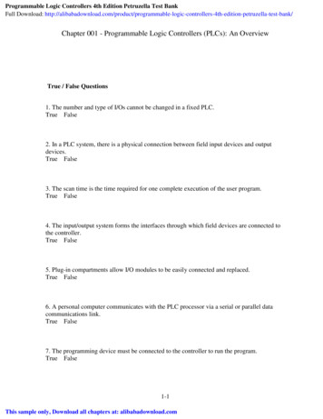
Installation InstructionsMicroLogix 1200 Programmable Controllers(Cat. No. 1762-L24AWA, 1762-L24BWA, 1762-L24BXB, 1762-L40AWA,1762-L40BWA, 1762-L40BXB, 1762-L24AWAR, 1762-L24BWAR,1762-L24BXBR, 1762-L40AWAR, 1762-L40BWAR, com/idc/groups/literature/documents/in/1762-in006 -mu-p.pdfFRCette publication est disponible en français sous forme électronique (fichier PDF). Pour latélécharger, rendez-vous sur la page Internet indiquée ci-dessus.ITQuesta pubblicazione è disponibile in Italiano in formato PDF. Per scaricarla collegarsi al sitoWeb indicato sopra.DEDiese Publikation ist als PDF auf Deutsch verfügbar. Gehen Sie auf die oben genannteWeb-Adresse, um nach der Publikation zu suchen und sie herunterzuladen.ESEsta publicación está disponible en español como PDF. Diríjase a la dirección web indicadaarriba para buscar y descarga esta publicación.PTEsta publicação está disponível em portugués como PDF. Vá ao endereço web que apareceacima para encontrar e fazer download da publicação.
Installation InstructionsMicroLogix 1200 Programmable Controllers(Cat. No. 1762-L24AWA, 1762-L24BWA, 1762-L24BXB, 1762-L40AWA,1762-L40BWA, 1762-L40BXB, 1762-L24AWAR, 1762-L24BWAR,1762-L24BXBR, 1762-L40AWAR, 1762-L40BWAR, 1762-L40BXBR)Inside . . .Important User Information . 4For More Information . 5Overview . 6Controller Description . 7Hazardous Location Considerations . 8Mounting the Controller . 10Connecting 1762 I/O Expansion Modules . 14Wiring the Controller . 15Specifications . 21
4MicroLogix 1200 Programmable ControllersImportant User InformationSolid state equipment has operational characteristics differing from those of electromechanical equipment.Safety Guidelines for the Application, Installation and Maintenance of Solid State Controls (PublicationSGI-1.1 available from your local Rockwell Automation sales office or online athttp://www.ab.com/manuals/gi) describes some important differences between solid state equipment andhard-wired electromechanical devices. Because of this difference, and also because of the wide variety ofuses for solid state equipment, all persons responsible for applying this equipment must satisfy themselvesthat each intended application of this equipment is acceptable.In no event will Rockwell Automation, Inc. be responsible or liable for indirect or consequential damagesresulting from the use or application of this equipment.The examples and diagrams in this manual are included solely for illustrative purposes. Because of the manyvariables and requirements associated with any particular installation, Rockwell Automation, Inc. cannotassume responsibility or liability for actual use based on the examples and diagrams.No patent liability is assumed by Rockwell Automation, Inc. with respect to use of information, circuits,equipment, or software described in this manual.Reproduction of the contents of this manual, in whole or in part, without written permission of RockwellAutomation, Inc. is prohibited.Throughout this manual we use notes to make you aware of safety considerations.WARNINGIdentifies information about practices or circumstances that can cause an explosion in ahazardous environment, which may lead to personal injury or death, property damage,or economic loss.IMPORTANTIdentifies information that is critical for successful application and understanding of theproduct.ATTENTIONIdentifies information about practices or circumstances that can lead to personal injuryor death, property damage, or economic loss. Attentions help you: identify a hazard avoid a hazard recognize the consequenceSHOCK HAZARDBURN HAZARDLabels may be located on or inside the drive to alert people that dangerous voltage maybe present.Labels may be located on or inside the drive to alert people that surfaces may bedangerous temperatures.Publication 1762-IN006C-EN-P - September 2009
MicroLogix 1200 Programmable Controllers5For More InformationRelated PublicationsForRefer to this DocumentPub. No.A more detailed description of how toinstall and use your MicroLogix 1200programmable controller and expansionI/O system.MicroLogix 1200 ProgrammableControllers User Manual1762-UM001A reference manual that contains dataand function files, instruction set, andtroubleshooting information forMicroLogix 1200 and MicroLogix 1500.MicroLogix 1200 andMicroLogix 1500 Instruction SetReference Manual1762-RM001Information on installing and using 1762expansion I/O modules.Installation Instructions are includedwith each module. Also available viawww.theautomationbookstore.com.1762-INxxxMore information on proper wiring andgrounding techniques.Industrial Automation Wiring andGrounding Guidelines1770-4.1If you would like a manual, you can: download a free electronic version from the internet:http://literature.rockwellautomation.com\ purchase a printed manual by contacting your local Allen-Bradley distributor orRockwell Automation representativePublication 1762-IN006C-EN-P - September 2009
6MicroLogix 1200 Programmable ControllersOverviewMicroLogix 1200 Controllers are suitable for use in an industrial environment wheninstalled in accordance with these instructions. Specifically, this equipment is intended for usein clean, dry environments (Pollution degree 2(1)) and to circuits not exceeding Over VoltageCategory II(2) (IEC 60664-1).(3)Install your controller using these installation instructions.debris stripATTENTIONATTENTIONDo not remove the protective debris strip until after thecontroller and all other equipment in the panel near thecontroller is mounted and wiring is complete. Once wiring iscomplete, remove protective debris strip. Failure to removestrip before operating can cause overheating.Electrostatic discharge can damage semiconductor devicesinside the controller. Do not touch the connector pins or othersensitive areas.(1)Pollution Degree 2 is an environment where, normally, only non-conductive pollution occurs except that occasionally atemporary conductivity caused by condensation shall be expected.(2)Over Voltage Category II is the load level section of the electrical distribution system. At this level transient voltages arecontrolled and do not exceed the impulse voltage capability of the product’s insulation.(3)Pollution Degree 2 and Over Voltage Category II are International Electrotechnical Commission (IEC) designations.Publication 1762-IN006C-EN-P - September 2009
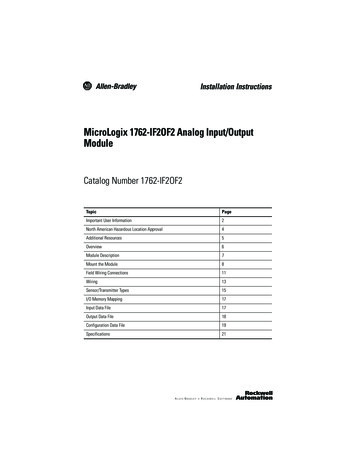
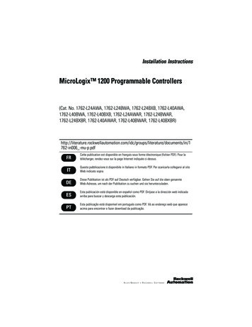
MicroLogix 1200 Programmable Controllers7Controller Description1Terminal Blocks7Terminal Doors and Label1(Removable Terminal Blocks on40-point controllers only)2Bus Connector Interface toExpansion I/O8Trim Pots3Input LEDs9Default Communications Push Button4Output LEDs10Memory Module Port Cover(1) -orMemory Module and/or Real Time Clock(2)5Communication Port (Channel 0)11DIN Rail Latches6Status LEDs12Programmer/HMI Port(Equipped with 1762-LxxxxxR controllers only)(1)Shipped with controller(2)Optional equipment.Publication 1762-IN006C-EN-P - September 2009
8MicroLogix 1200 Programmable ControllersCatalog NumberDescriptionInput PowerInputsOutputs1762-L24AWA, -L24AWAR120/240V ac(14) 120V ac(10) relay1762-L24BWA, -L24BWAR120/240V ac(10) 24V dc(10) relay(4) fast 24V dc1762-L24BXB, -L24BXBR24V dc(10) 24V dc(5) relay, (4) 24V dc FET(4) fast 24V dc(1) high-speed 24V dc FET1762-L40AWA, -L40AWAR120/240V ac(24) 120V ac(16) relay1762-L40BWA, -L40BWAR120/240V ac(20) 24V dc(16) relay1762-L40BXB, -L40BXBR24V dc(20) 24V dc(8) relay, (7) 24V dc FET(4) fast 24V dc(1) high-speed 24V dc FET(4) fast 24V dcHazardous Location ConsiderationsThis equipment is suitable for use in Class I, Division 2, Groups A, B, C, D or non-hazardouslocations only. The following WARNING statement applies to use in hazardous locations.WARNINGEXPLOSION HAZARD Substitution of components may impair suitability for ClassI, Division 2. Do not replace components or disconnect equipmentunless power has been switched off. Do not connect or disconnect components unless powerhas been switched off. This product must be installed in an enclosure. All cablesconnected to the product must remain in the enclosure orbe protected by conduit or other means. All wiring must comply with N.E.C. article 501-4(b).Use only the following communication cables in Class I, Division 2 hazardous locations.Publication 1762-IN006C-EN-P - September 2009
MicroLogix 1200 Programmable ControllersEnvironment ClassificationCommunication CablesClass I, Division 2 Hazardous Environment1761-CBL-PM02 Series C or later91761-CBL-HM02 Series C or later1761-CBL-AM00 Series C or later1761-CBL-AP00 Series C or later2707-NC8 Series B or later2707-NC10 Series B or later2707-NC11 Series B or laterEnvironnements dangereuxCet équipement est conçu pour être utilisé dans des environnements de Classe I, Division 2,Groupes A, B, C, D ou non dangereux. La mise en garde suivante s’applique à utilisation enenvironnements dangereux.AVERTISSEMENTDANGER D’EXPLOSION La substitution de composants peut rendre cet équipementimpropre à une utilisation en environnement de Classe I,Division 2. Ne pas remplacer de composants ou déconnecterl’équipement sans s’être assuré que l’alimentation estcoupée. Ne pas connecter ou déconnecter des composants sanss’être assuré que l’alimentation est coupée. Ce produit doit être installé dans une armoire. Tous lescâbles connectés à l’appareil doivent rester dans l’armoireou être protégés par un conduit ou tout autre moyen. L’ensemble du câblage doit être conforme à laréglementation en vigueur dans les pays où l’appareil estinstallé.Utiliser uniquement les câbles de communication suivants dans les environnementsdangereux de Classe I, Division 2.Publication 1762-IN006C-EN-P - September 2009
10MicroLogix 1200 Programmable ControllersClassification des environnementsCâbles de communicationEnvironnement dangereux de Classe I, Division 21761-CBL-PM02 série C ou ultérieure1761-CBL-HM02 série C ou ultérieure1761-CBL-AM00 série C ou ultérieure1761-CBL-AP00 série C ou ultérieure707-NC8 série B ou ultérieure2707-NC10 série B ou ultérieure2707-NC11 série B ou ultérieureMounting the ControllerGeneral ConsiderationsMost applications require installation in an industrial enclosure to reduce the effects ofelectrical interference and environmental exposure. Locate your controller as far as possiblefrom power lines, load lines, and other sources of electrical noise such as hard-contactswitches, relays, and AC motor drives. For more information on proper grounding guidelines,see the Industrial Automation Wiring and Grounding Guidelines publication 1770-4.1.ATTENTIONATTENTIONVertical mounting is not recommended due to thermalconsiderations.Be careful of metal chips when drilling mounting holes foryour controller or other equipment within the enclosure orpanel. Drilled fragments that fall into the controller couldcause damage. Do not drill holes above a mounted controllerif the protective debris strips have been removed.Publication 1762-IN006C-EN-P - September 2009
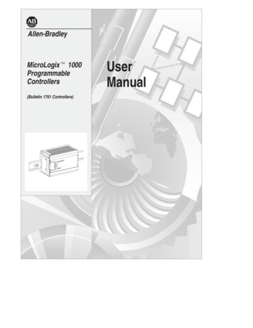
MicroLogix 1200 Programmable Controllers11Mounting DimensionsCCABA1762-L24AWA, 1762-L24BWA, 1762-L24BXB,1762-L24AWAR, 1762-L24BWAR, 1762-L24BXBRDimensionB1762-L40AWA, 1762-L40BWA, 1762-L40BXB,1762-L40AWAR, 1762-L40BWAR, ,L24BXBRL40AWA,L40AWARL40BWA,L40BWARA90 mm (3.5 in.)B110 mm (4.33 in.)160 mm (6.30 in.)C87 mm (3.43 in.)87 mm (3.43 in.)L40BXB,L40BXBR90 mm (3.5 in.)Publication 1762-IN006C-EN-P - September 2009
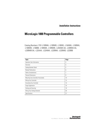
12MicroLogix 1200 Programmable ControllersController SpacingThe controller mounts horizontally, with the expansion I/O extending to the right of thecontroller. Allow 50 mm (2 in.) of space on all but the right side for adequate ventilation, asshown below.TopSideBottomDIN Rail MountingThe maximum extension of the latch is 14 mm (0.55 in.) in the open position. A flat-bladescrewdriver is required for removal of the controller. The controller can be mounted toEN50022-35x7.5 or EN50022-35x15 DIN rails. DIN rail mounting dimensions are shownbelow.BACPublication 1762-IN006C-EN-P - September 2009
MicroLogix 1200 Programmable ControllersDimensionHeightA90 mm (3.5 in.)B27.5 mm (1.08 in.)C27.5 mm (1.08 in.)13To install your controller on the DIN rail:1. Mount your DIN rail. (Make sure that the placement of the controller on the DIN railmeets the recommended spacing requirements, see Controller Spacing on page 12.Refer to the mounting template inside the back cover of this document.)2. Close the DIN latch, if it is open.3. Hook the top slot over the DIN rail.4. While pressing the controller down against the top of the rail, snap the bottom of thecontroller into position.5. Leave the protective debris strip attached until you are finished wiring the controllerand any other devices.To remove your controller from the DIN rail:1. Place a flat-blade screwdriver in the DIN rail latch at the bottom of the controller.2. Holding the controller, pry downward on the latch until the latch locks in the openposition.3. Repeat steps 1 and 2 for the second DIN rail latch.4. Unhook the top of the DIN rail slot from the rail.openclosedPublication 1762-IN006C-EN-P - September 2009
14MicroLogix 1200 Programmable ControllersPanel MountingMount to panel using #8 or M4 screws. To install your controller using mounting screws:1. Remove the mounting template from inside the back cover of this document.2. Secure the template to the mounting surface. (Make sure your controller is spacedproperly. See Controller Spacing on page 12.)3. Drill holes through the template.4. Remove the mounting template.5. Mount the controller.MountingTemplate6. Leave the protective debris stripin place until you are finishedwiring the controller and anyother devices.Connecting 1762 I/O Expansion ModulesATTENTIONRemove power to the system before installing expansion I/Oor damage to the controller may result.Connect 1762 I/O after mounting the controller. Remove the expansion port cover to installexpansion I/O modules. Plug the ribbon cable connector into the bus connector. Replace thecover as shown below.Publication 1762-IN006C-EN-P - September 2009
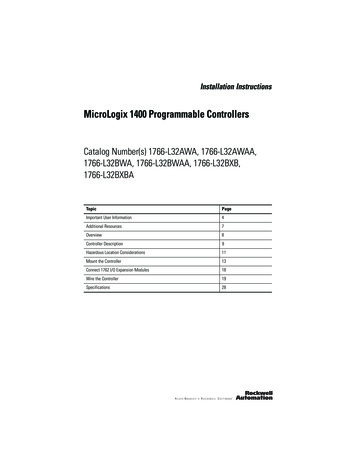
MicroLogix 1200 Programmable ControllersIMPORTANT15Ensure that your system power supply is sufficient to supportthe number of I/O modules you are installing in the system. Asystem loading worksheet is provided in the MicroLogix 1200Programmable Controllers User Manual, publication1762-UM001.For detailed information on using expansion I/O, refer to the installation instructions foryour expansion module.Wiring the ControllerTerminal Block LayoutsTIPThe shading in the following terminal block illustrationsindicates which terminals are tied to which 24BWARNCIN 0IN 2COM1IN 5IN 7IN 9IN 11IN 13NCCOM0VACL1VAC OUT 0 OUT 1 OUT 2 VAC OUT 5 OUT 6 OUT 8DC 3NEUTIN 3VACDC 0VACDC 1IN 0IN 2 24VDC24COMIN 1COM0IN 1IN 4IN 8 IN 10IN 12VAC OUT 3 OUT 4 VAC OUT 7 OUT 9DC 2DC 4COM1IN 3IN 5IN 4VAC VACL1 NEUT OUT 0 OUT 1 OUT 2VAC VACDC 0 DC 1IN 6IN 6IN 7IN 8IN 9 IN 11IN 10IN 13IN 12VACDC 3 OUT 5 OUT 6 OUT 8VACVACOUT 7 OUT 9OUT 3 OUT 4DC 2DC 4Publication 1762-IN006C-EN-P - September 2009
16MicroLogix 1200 Programmable Controllers1762-L24BXB,1762-L24BXBRNCIN 0COM0NC 24 VDCVDC NEUTNCNCIN 024COMIN 12OUT0OUT1OUT2OUT4OUT6OUT8VACDC 1COM1IN 3VACL1VACNEUTOUT0VACL1VACNEUTOUT0VACDC 01762-L40BXB,1762-L40BXBRNCNCCOM0IN 0IN 2IN 1 24VDCVDC NEUTOUT0VACDC 0COM1VACDC 1OUT5COM2OUT7OUT9IN 5IN 7IN 8IN 10IN 12IN 14IN 18IN 20IN 22IN 13IN 15IN 17IN 19IN 21OUT1OUT2OUT5OUT8OUT10VACDC 5OUT13OUT15OUT4IN 5IN 7IN 8 IN 10IN 6OUT2COM2IN 7OUT4OUT3Publication 1762-IN006C-EN-P - September 2009OUT6OUT5IN 11OUT8OUT7IN 14IN 16IN 18IN 15OUT10OUT9IN 14IN 13COM2OUT9OUT12OUT8IN 12IN 11OUT11IN 13VACDC 4OUT6IN 9IN 12OUT7IN 8 IN 10COMIN 62OUT4IN 9OUT9VACDC 4OUT6OUT5VACDC 3IN 5OUT2OUT7OUT3OUT3IN 4VACDC 3VACDC 2VACDC 2VDC2IN 16IN 9 IN 11OUT1OUT1OUT3IN 4VACDC 1IN 3VDC2IN 4COM1IN 3VACDC 3COMIN 62VACDC 1IN 2IN 1IN 13IN 8 IN 10IN 1COM0IN 11IN 6IN 2IN 0IN 9IN 4COM0 24VDCIN 7IN 3VACDC 01762-L40BWA,1762-L40BWARIN 5IN 1VACDC 01762-L40AWA,1762-L40AWARCOM1IN 2VACDC 3VACDC 5OUT11IN 16IN 15OUT10IN 17VACDC 4OUT11IN 20 IN 22OUT14IN 20 IN 22IN 19OUT13IN 21OUT15OUT13IN 18IN 17OUT14IN 19OUT12IN 21OUT15OUT OUT1214IN 23IN 23IN 23
MicroLogix 1200 Programmable Controllers17Wire RequirementsWire TypeWire Size (2 wire maximum per terminal screw)SolidCu-90 C (194 F)#14 to #22 AWGStrandedCu-90 C (194 F)#16 to #22 AWGWiring torque 0.791 Nm (7 in-lb) ratedATTENTIONBe careful when stripping wires. Wire fragments that fall intothe controller could cause damage. Once wiring is complete,be sure the controller is free of all metal fragments beforeremoving the protective debris strip. Failure to remove thestrip before operating can cause overheating.Wiring RecommendationWhen wiring without spade lugs, keep the finger-safe covers in place. Loosen the terminalscrew and route the wires through the opening in the finger-safe cover. Tighten the terminalscrew, making sure the pressure plate secures the wire.Finger-safe coverPublication 1762-IN006C-EN-P - September 2009
18MicroLogix 1200 Programmable ControllersSpade Lug RecommendationThe diameter of the terminal screw head is 5.5 mm (0.220 in.). The input and outputterminals of the MicroLogix 1200 controller are designed for the following spade lugs. Theterminals will accept a 6.35mm (0.25 in.) wide spade (standard for #6 screw for up to 14AWG) or a 4 mm (metric #4) fork terminal.When using spade lugs, use a small, flat-blade screwdriver to pry the finger-safe cover fromthe terminal blocks. Then loosen the terminal screw.Finger-safe coverTIPIf you wire the terminal block with the finger-safe coverremoved, you may not be able to put it back on the terminalblock if the wires are in the way.Publication 1762-IN006C-EN-P - September 2009
MicroLogix 1200 Programmable Controllers19Surge SuppressionATTENTIONInductive load devices such as motor starters and solenoidsrequire the use of some type of surge suppression to protectthe controller output. Switching inductive loads without surgesuppression can significantly reduce the life of relay contactsor damage transistor outputs. By using suppression, you alsoreduce the effects of voltage transients caused by interruptingthe current to that inductive device, and prevent electricalnoise from radiating into system wiring. Refer to theMicroLogix 1200 Programmable Controller User Manual,publication 1762-UM001, for more information on surgesuppression.Publication 1762-IN006C-EN-P - September 2009
20MicroLogix 1200 Programmable ControllersGrounding the ControllerIn solid-state control systems, grounding and wire routing helps limit the effects of noise dueto electromagnetic interference (EMI). Run the ground connection from the ground screw ofthe controller to the ground bus prior to connecting any devices. Use AWG #14 wire. ForAC-powered controllers, this connection must be made for safety purposes.ATTENTIONAll devices connected to the RS-232 channel must bereferenced to controller ground, or be floating (not referencedto a potential other than ground). Failure to follow thisprocedure may result in property damage or personal injury. For 1762-L24BWA, 1762-L40BWA, 1762-L24BWAR and1762-L40BWAR controllers:The COM of the sensor supply is also connected to chassisground internally. The 24V dc sensor power sourceshould not be used to power output circuits. It shouldonly be used to power input devices. For 1762-L24BXB, 1762-L40BXB, 1762-L24BXBR and1762-L40BXBR controllers:The VDC NEUT or common terminal of the power supplyis also connected to chassis ground internally.You must also provide an acceptable grounding path for each device in your application. Formore information on proper grounding guidelines, refer to the Industrial Automation Wiring andGrounding Guidelines, publication 1770-4.1.Publication 1762-IN006C-EN-P - September 2009
MicroLogix 1200 Programmable Controllers21SpecificationsGeneral BXB,L40BXBRHeight: 90 mm,104 mm (with DIN latch open)Width: 110 mm, Depth: 87 mmHeight: 90 mm104 mm (with DIN latch open)Width: 160 mm, Depth: 87 mmShipping Weight0.9 kg (2.0 lbs)1.1 kg (2.4 lbs)Number of I/O14 inputs and 10 outputs24 inputs, 16 outputsPower Supply100 to 240V ac( -15%, 10%)at 47 to 63 HzHeat DissipationRefer to the MicroLogix 1200 Programmable Controllers User Manual.Power SupplyInrush120V ac: 25A for 8 msDimensionsPower SupplyUsagePowerSupplyOutput5V dc24V dcSensor PowerOutput24V dc( -15%, 10%)Class 2SELV100 to 240V ac( -15%, 10%)at 47 to 63 Hz24V dc( -15%, 10%)Class 2SELV120V ac: 25A for 8 ms240V ac: 40A for 4 ms24V dc:15A for20 ms240V ac: 40A for 4 ms24V dc:15A for30 ms68 VA70 VA27W80 VA82 VA40W400 mA400 mA(1)400 mA600 mA600 mA(2)600 mA350 mA350 mA(1)350 mA500 mA500 mA(2)500 mAnone24V dc at250 mA400 µFnonenone24V dc at400 mA400 µFnonemax.(1)max.(2)Input Circuit Type120V ac24V dcsink/source24V dcsink/source120V ac24V dcsink/source24V dcsink/sourceOutput perating Temp. 0 C to 55 C ( 32 F to 131 F) ambientStorage Temp.-40 C to 85 C (-40 F to 185 F) ambientOperatingHumidity5% to 95% relative humidity (non-condensing)VibrationOperating: 10 to 500 Hz, 5G, 0.030 in. max. peak-to-peak, 2 hours each axisRelay Operation: 1.5GPublication 1762-IN006C-EN-P - September 2009
22MicroLogix 1200 Programmable ,L40BXBRShockOperating: 30G; 3 pulses each direction, each axisRelay Operation: 7GNon-Operating: 50G panel mounted (40G DIN Rail mounted); 3 pulses each direction, eachaxisAgencyCertification UL 508 C-UL under CSA C22.2 no. 142 Class I, Div. 2, Groups A, B, C, D(UL 1604, C-UL under CSA C22.2 no. 213) CE/C-Tick compliant for all applicable directivesElectrical/EMCThe controller has passed testing at the following levels: IEC1000-4-2: 4 kV contact, 8 kV air, 4 kV indirect IEC1000-4-3: 10V/m, 80 to 1000 MHz, 80% amplitude modulation, 900 MHz keyedcarrier IEC1000-4-4: 2 kV, 5 kHz; communications cable: 1 kV, 5 kHz IEC1000-4-5: communications cable 1 kV galvanic gunI/O: 2 kV CM (common mode), 1 kV DM (differential mode)AC Power Supply: 4 kV CM (common mode), 2 kV DM (differential mode)DC Power Supply: 500V CM (common mode), 500V DM (differential mode) IEC1000-4-6: 10V, communications cable 3VTerminal ScrewTorque0.791 Nm (7 in-lb) rated(1)Do not allow the total load power consumed by the 5V dc, 24V dc, and sensor power outputs to exceed 12W.(2)Do not allow the total load power consumed by the 5V dc, 24V dc, and sensor power outputs to exceed 16W.Refer to the MicroLogix 1200 User Manual for system validation worksheets.Publication 1762-IN006C-EN-P - September 2009
MicroLogix 1200 Programmable Controllers23Input SpecificationsDescription1762-L24AWA, -L40AWA1762-L24AWAR, -L40AWAROn-State VoltageRange79 to 132V ac1762-L24BWA, -L24BXB, -L40BWA, -L40BXB1762-L24BWAR, -L24BXBR, -L40BWAR, -L40BXBRInputs 0 through 3Inputs 4 and higher14 to 24V dc10 to 24V dc( 10% at 55 C/131 F)( 25% at 30 C/86 F)( 10% at 55 C/131 F)( 25% at 30 C/86 F)Off-State VoltageRange0 to 20V ac0 to 5V dcOperatingFrequency47 Hz to 63 Hz0 Hz to 20 kHz0 Hz to 1 kHz(scan time dependent) minimum 5.0 mA at 79V ac 2.5 mA at 14V dc 2.0 mA at 10V dc nominal 12 mA at 120V ac 7.3 mA at 24V dc 8.9 mA at 24V dc maximum 16.0 mA at 132V ac 12.0 mA at 30V dc 12.0 mA at 30V dcOff-State LeakageCurrent2.5 mA max.1.5 mA min.NominalImpedance12KΩ at 50 Hz3.3KΩOn-State Current:2.7KΩ10KΩ at 60 HzInrush Current(max.) at 120V ac250 mANot ApplicablePublication 1762-IN006C-EN-P - September 2009
24MicroLogix 1200 Programmable ControllersOutput WAR-L40BWAR-L40BXB-L40BXBR7.5A8A8ARelay and FET OutputsMaximum Controlled Load1440 VAMaximum Continuous Current:Current per Group Common8ACurrent per Controllerat 150V max30A or total of per-point loads, whichever is lessat 240V max20A or total of per-point loads, whichever is lessRelay OutputsTurn On Time/Turn Off Time10 msec (minimum)(1)Load Current10 mA (minimum)(1)scan time dependentRelay Contact RatingsMaximum MakeBreak240V ac7.5A0.75A2.5A(2)1800 VA180 VA120V ac15A1.5A2.5A(2)1800 VA180 VA125V dc0.22A(1)1.0A24V dc1.2A(1)2.0A28 VA(1)For dc voltage applications, the make/break ampere rating for relay contacts can be determined by dividing 28 VA by theapplied dc voltage. For example, 28 VA/48V dc 0.58A. For dc voltage applications less than 14V, the make/break ratingsfor relay contacts cannot exceed 2A.(2)1.5A above 40 C.Publication 1762-IN006C-EN-P - September 2009
MicroLogix 1200 Programmable Controllers25BXB FET Output SpecificationsDescriptionGeneral OperationPower Supply Voltage24V dc ( -15%, 10%)High Speed Operation(1)(Output 2 Only)On-State Voltage Drop: at maximum load current 1V dc Not Applicable at maximum surge current 2.5V dc Not Applicable maximum load See graphs below. 100 mA minimum load 1.0 mA 10 mA maximum leakage 1.0 mA 1.0 mACurrent Rating per PointMaximum Output Current (temperature dependent):FET Total Current(1762-L40BXB and L40BXBR)FET Current per Point(1762-L24BXB, L40BXB1762-L24BXBR, L40BXBR)2.01.757.01.5A, 30 C (86 F)6.01.251.01.0A, 55 C (131 F)Valid0.750.5Current (Amps)1.5Current (Amps)8.0A, 30 C (86 F)8.00.255.5A, 55 C (131 F)5.04.0Valid3.02.01.010 C(50 F)30 C(86 F)50 C(122 F)10 C(50 F)70 C(158 F)Temperature30 C(86 F)50 C(122 F)70 C(158 F)TemperatureSurge Current per Point: peak current 4.0A Not Applicable maximum surge duration 10 msec Not Applicable maximum rate of repetition at 30 C (86 F) once every second Not Applicable maximum rate of repetition at 55 C (131 F) once every 2seconds Not ApplicablePublication 1762-IN006C-EN-P - September 2009
26MicroLogix 1200 Programmable ControllersDescriptionGeneral OperationHigh Speed Operation(1)(Output 2 Only)Turn-On Time (maximum)0.1 msec6 µsecTurn-Off Time (maximum)1.0 msec18 µsecRepeatability (maximum)n/a2 µsecDrift (maximum)n/a1 µsec per 5 C (9 F)(1)Output 2 is designed to provide increased functionality over the other FET outputs. Output 2 may be used like the other FETtransistor outputs, but in addition, within a limited current range, it may be operated at a higher speed. Output 2 alsoprovides a pulse train output (PTO) or pulse width modulation output (PWM) function.Working VoltageDescription1762-L24AWA, 1762-L40AWA, 1762-L24AWAR, 1762-L40AWARPower Supply Input toBackplane IsolationVerified by one of the following dielectric tests: 1836V ac for 1 second or2596V dc for 1 second265V ac Working Voltage (IEC Class 2 reinforced insulation)Input Group to BackplaneIsolationVerified by one of the following dielectric tests:1517V ac for 1 second or 2145Vdc for 1 second132V ac Working Voltage (IEC Class 2 reinforced insulation)Input Group to Input GroupIsolationVerified by one of the following dielectric tests:1517V ac for 1 second or 2145Vdc for 1 second132V ac Working Voltage (basic insulation)Output Group to BackplaneIsolationVerified by one of the following dielectric tests: 1836V ac for 1 second or2596V dc for 1 second265V ac Working Voltage (IEC Class 2 reinforced insulation)Output Group to OutputGroup IsolationVerified by one of the following dielectric tests: 1836V ac for 1 second or2596V dc for 1second265V ac Working Voltage (basic insulation) 150V ac Working Voltage (IEC Class2 reinforced insulation).Publication 1762-IN006C-EN-P - September 2009
MicroLogix 1200 Programmable Controllers27Description1762-L24BWA, 1762-L40BWA, 1762-L24BWAR, 1762-L40BWARPower Supply Input toBackplane IsolationVerified by one of the following dielectric tests:1836V ac for 1 second or 2596Vdc for 1 second265V ac Working Voltage (IEC Class 2 reinforced insulation)Input Group to BackplaneIsolation and Input Group toInput Group IsolationVerified by one of the following dielectric tests: 1200V ac for 1 second or1697V dc for 1 secondOutput Group to BackplaneIsolationVerified by one of the following dielectric tests: 1836V ac for 1 second or2596V dc for 1 second75V dc Working Voltage (IEC Class 2 reinforced insulation)265V ac Working Voltage (IEC Class 2 reinforced insulation).Output Group to OutputGroup IsolationVerified by one of the following dielectric tests: 1836V ac for 1 second or2596V dc for 1 second265V ac Working Voltage (basic insulation) 150V Working Voltage (IEC Class 2reinforced insulation)Description1762-L24BXB, 1762-L40BXB, 1762-L24BXBR, 1762-L40BXBRInput Group to BackplaneIsolation and Input Group toInput Group IsolationVerified by one of the following dielectric tests: 1200V ac for 1 second or1697V dc for 1 secondFET Output Group toBackplane IsolationVerified by one of the following dielectric tests: 1200V ac for 1 second or1697V dc for 1 second75V dc Working Voltage (IEC Class 2 reinforced insulation)75V dc Working Voltage (IEC Class 2 reinforced insulation)Relay Output Group toBackplane Isol
1762-L40BWA, -L40BWAR 120/240V ac (20) 24V dc (4) fast 24V dc (16) relay 1762-L40BXB, -L40BXBR 24V dc (20) 24V dc (4) fast 24V dc (8) relay, (7) 24V dc FET (1) high-speed 24V dc FET WARNING EXPLOSION HAZARD Substitution of components may impair suitability for Class I, Division 2. Do not replace components or disconnect equipment