Transcription
SMVector ESVZAR0 RS-485 Modbus Communication ModuleCommunications Interface Reference Guide
About These InstructionsThis documentation applies to the ESVZAR0 RS-485/Modbus communications option for the SMVector inverter modelsup to 10HP. This documentation should be used in conjunction with the SMVector Operating Instructions (DocumentSV01) that shipped with the drive. These documents should be read in their entirety as they contain important technicaldata and describe the installation and operation of the drive and this option.WARNING!The information in this document is based on RS-485 Modbus Communication Modulesoftware version 1.01. If a future revision of software contains differences in the registernumbering or register definitions, drive operation could be seriously affected. If driveparameter P494 does not display 1.01, 1.10 or 1.30, then writing to any drive registerover the Modbus network MUST NOT BE ATTEMPTED as it would have the potentialfor unexpected consequences potentially resulting in damage to the equipment orharm to personnel. Future releases of module software require that the appropriatedocumentation be used for implementation. 2007 Lenze AC Tech CorporationNo part of this documentation may be copied or made available to third parties without the explicit written approvalof Lenze AC Tech Corporation.All information given in this documentation has been carefully selected and tested for compliance with the hardwareand software described. Nevertheless, discrepancies cannot be ruled out. We do not accept any responsibility norliability for damages that may occur. Any necessary corrections will be implemented in subsequent editions.
Contents12345678Safety Information.3Introduction.52.1Module Specifications.52.2Module Identification.6Installation.73.1Mechanical Installation.73.2RS-485 Terminal Block.83.3Electrical Installation.83.3.1 Cable Types.83.3.2 Connections and Shielding.83.3.3 Network Termination.9Extended Parameters for Modbus RTU.104.1Parameter Menu.10Modbus Protocol Details.125.1Data Transmission.125.2Register Numbering.125.3Supported Function Codes.12Modbus Message Details.136.1Register Reading.136.1.1 Message structure for reading one 16-bit register.136.1.2 Message structure for reading two 16-bit registers.136.1.3 Message structure for reading one 32-bit register.146.1.4 Message structure for reading one 4 word register.146.1.5 Message structure for reading six 16-bit registers.146.2Register Writing.156.2.1 Message structure for reading one word.156.3No Response Conditions.156.4Exception Responses.156.4.1 Message structure for an exception response to a read request (03).156.4.2 Message structure for an exception response to a write request (06).156.4.3 Exception Codes (EC).15Commissioning.167.1Drive Monitoring.167.2Drive Programming and Control.167.3Unlocking & Locking Drive Controls & Parameters.167.4Network Watchdog Timer.177.5Watchdog Timer Controls.177.5.1 Watchdog Time-out Period (P425).177.5.2 Watchdog Time-out Action (P426).17Typical Network Applications.188.1Controlling the Drive.188.2Changing Drive Parameters.188.3Controlling Frequency, PID & Torque Setpoints.18CMVMB401C1
Contents9Drive Registers.199.1Data Internal vs. Display Representation.199.2Drive Control Registers.199.2.1 Drive Control - Register #1.209.2.2 Drive Size - Register #21.219.2.3 Drive Status - Register #23.229.2.4 Load - Register #26.229.2.5 Run Status - Register #26.239.2.6 Actual Direction - Register #27.239.2.7 Control Mode - Register #27.239.2.8 Speed Source - Register #28.249.2.9 Auto/Manual Reference - Register #28.249.2.10 Present Fault - Register #29.259.2.11 Commanded Direction - Register #29.259.2.12 PID Registers.259.2.13 Parameter Version - Register #50.269.2.14 Network Controlled Digital Output - Register #70.269.2.15 Network Controlled Analog Output - Register #71.2610 Programming Parameters.2710.1 Negative Number Transmission.2710.2 Terminal and Protection Status (P530).2710.3 Keypad Status (P531).2811 Troubleshooting and Fault Elimination.2911.1 Faults.2911.2 Troubleshooting.292CMVMB401C
Safety Information1Safety InformationGeneralSome parts of Lenze controllers (frequency inverters, servo inverters, DC controllers) can be live, moving and rotating.Some surfaces can be hot.Non-authorized removal of the required cover, inappropriate use, and incorrect installation or operation creates therisk of severe injury to personnel or damage to equipment.All operations concerning transport, installation, and commissioning as well as maintenance must be carried outby qualified, skilled personnel (IEC 364 and CENELEC HD 384 or DIN VDE 0100 and IEC report 664 or DIN VDE0110and national regulations for the prevention of accidents must be observed).According to this basic safety information, qualified skilled personnel are persons who are familiar with the installation,assembly, commissioning, and operation of the product and who have the qualifications necessary for their occupation.Application as directedDrive controllers are components which are designed for installation in electrical systems or machinery. They arenot to be used as appliances. They are intended exclusively for professional and commercial purposes according toEN 61000-3-2. The documentation includes information on compliance with the EN 61000-3-2.When installing the drive controllers in machines, commissioning (i.e. the starting of operation as directed) isprohibited until it is proven that the machine complies with the regulations of the EC Directive 2006/42/EC (MachineryDirective); EN 60204 must be observed.Commissioning (i.e. starting of operation as directed) is only allowed when there is compliance with the EMCDirective (2004/108/EEC). The drive controllers meet the requirements of the Low Voltage Directive 2006/95/EC.The harmonised standards of the series EN 50178/DIN VDE 0160 apply to the controllers.The availability of controllers is restricted according to EN 61800-3. These products can cause radiointerference in residential areas. In this case, special measures can be necessary.InstallationEnsure proper handling and avoid excessive mechanical stress. Do not bend any components and do not changeany insulation distances during transport or handling. Do not touch any electronic components and contacts.Controllers contain electrostatically sensitive components, which can easily be damaged by inappropriate handling.Do not damage or destroy any electrical components since this might endanger your health!Electrical connectionWhen working on live drive controllers, applicable national regulations for the prevention of accidents (e.g. VBG 4)must be observed.The electrical installation must be carried out according to the appropriate regulations (e.g. cable cross-sections,fuses, PE connection). Additional information can be obtained from the documentation.The documentation contains information about installation in compliance with EMC (shielding, grounding, filters andcables). These notes must also be observed for CE-marked controllers.The manufacturer of the system or machine is responsible for compliance with the required limit values demandedby EMC legislation.CMVMB401C3
Safety InformationOperationSystems including controllers must be equipped with additional monitoring and protection devices according to thecorresponding standards (e.g. technical equipment, regulations for prevention of accidents, etc.). You are allowedto adapt the controller to your application as described in the documentation.DANGER! After the controller has been disconnected from the supply voltage, live components and powerconnection must not be touched immediately, since capacitors could be charged. Please observe thecorresponding notes on the controller.Do not continuously cycle input power to the controller more than once every three minutes.Please close all protective covers and doors during operation.WARNING!Network control permits automatic operation of the inverter drive. The system design must incorporateadequate protection to prevent personnel from accessing moving equipment while power is applied to thedrive system.Table 1: Pictographs used in these instructionsPictograph4Signal wordMeaningConsequences if ignoredDANGER!Warning of Hazardous ElectricalVoltage.Reference to an imminent danger that mayresult in death or serious personal injury if thecorresponding measures are not taken.WARNING!Impending or possible danger forpersonsDeath or injurySTOP!Possible damage to equipmentDamage to drive system or its surroundingsNOTEUseful tip: If observed, it will makeusing the drive easierCMVMB401C
Introduction2IntroductionThis reference guide assumes that the reader has a working knowledge of the Modbus RTU Protocol and familiaritywith the programming and operation of motion control equipment. This guide is intended as a reference only.Modbus is an internationally accepted asynchronous serial protocol designed for commercial and industrial automationapplications. The Modbus RTU architecture is based upon a PLC to device communication structure and, as suchis Master-Slave in orientation. The SMV drive, in this case, always acts as the slave in this network, responding tocommands and requests from the Master.While the Modbus RTU protocol does not specify the physical layer, the ESVZAR0 module uses the RS-485 physicalinterface which is quite common and well suited for the industrial environment. The ESVZAR0 module provides bothgalvanic and optical isolation of this physical interface.2.1Module SpecificationsTable 2 identifies the Modbus serial communication specifications. If the specification is fixed (non-adjustable)the value is shown under “Range”, if the specification is selectable, Table 2 identifies the Parameter and availablerange of selections.Table 2: Modbus SpecificationsDescriptionTypeRangeBaud RateSelectableP411 (2400, 4800, 9600, 19200, 38400, 57600, or 115200 bps)Data BitsFixed8Parity / Stop BitsSelectableP412 (None/1, None/2, Even/1, Odd/1)Network AddressSelectableP410 (1 - 247)Typical communications between master and slave would be: Write commands from Master Run command Frequency Reference Modification of Drive operating parameters Requests from Master Reporting of drive status Fault status (and fault history)The SMVector drive most nearly conforms to the Modicon Micro 84 in capabilities. This may be of importancewhen configuring networks for DDE Servers.CMVMB401C5
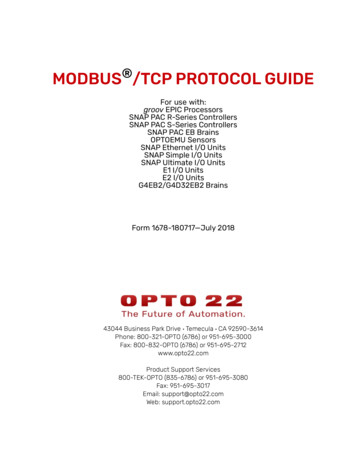
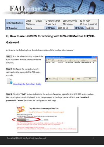
Introduction2.2Module IdentificationFigure 1 illustrates the labels on the SMV RS-485 communications module. The SMVector RS-485 module isidentifiable by: Two labels affixed to either side of the module. The color coded identifier label in the center of the module.Right-hand Label:Ratings & CertificationsCOMM I/O ONLYS/N: 123456789LISTEDFieldbus Identifier:R RS-485 (Modbus RTU/LECOM)R0Left-hand Label:Module DataSMV RS-485TYPE: ESVZAR0ID-NO: 12345678ESVZAR0-000XX1A10ABCDEA: Fieldbus ProtocolB: Model NumberC: Lenze Order NumberD: Firmware RevisionE: Hardware RevisionFigure 1: RS-485 Module Labels6CMVMB401C
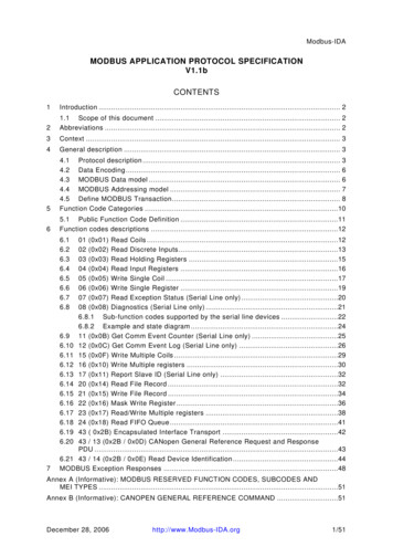
Installation3Installation3.1Mechanical Installation1. Ensure that for safety reasons the AC supply has been disconnected before opening the terminal cover.2. Insert the RS-485 option module in the terminal cover and securely “click” into position as illustrated in Figure 2.3. Wire the network cables to the connector provided, as detailed in paragraphs 3.2 (RS-485 Terminal Block) and3.3 (Electrical Installation), and plug the connector into the option module.4. Align terminal cover for re-fitting, connect the module umbilical cord to the drive then close the cover andsecure, as shown in Figure 3.1 2 3 4 50.5 Nm/ 4.5 lb-in 2.8 mm2(12-22 AWG)7mmNEMA 1 (IP31) ModelsNEMA 4X (IP65) ModelsFigure 2: Installing the RS-485 Communications ModuleNEMA 1 (IP31) ModelsNEMA 4X (IP65) ModelsFigure 3: Re-installing the Terminal CoverCMVMB401C7
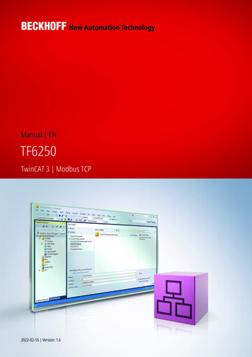
Installation3.2RS-485 Terminal BlockTable 3 describes the RS-485 terminal block. The 5 pole connector provides 2-wire connection to the network.Table 3: RS-485 Terminal BlockTerminalDescriptionImportant1Earth ground /shieldFor reliable communication make sure terminal isconnected to the Modbus network GND/common.If only two wires are used (TXA and TXB) in thenetwork, connect Terminal 1 to chassis/earth GND.Connector2TXA3No connection4TXBIf controller is located at either end of the network,a terminating resistor (120ohm typical) should beconnected across TXA and TXB5No connection14235Protection against contact All terminals have basic isolation (single insulating distance) Protection against contact can only be ensured by additional measures (i.e. double insulation)3.3Electrical Installation3.3.1Cable TypesFor RS-485 Modbus networks, use a quality shielded twisted pair cable. The use of low quality cable will result inexcess signal attenuation and data loss.3.3.2Connections and ShieldingTo ensure good system noise immunity all networks cables should be correctly grounded: Minimum grounding recommendation: ground the network cable once in every cubical. Ideal grounding recommendation: ground the network cable on or as near to each drive as possible. For wiring of cable to the connector plug the unscreened cable cores should be kept as short as possible;recommended maximum of 20mm. The shield connection of terminal 1 should also be wired to earth (PE).12345Connect todrive earth(PE)20mmmaxFigure 4: Connector Wiring Diagram8CMVMB401C
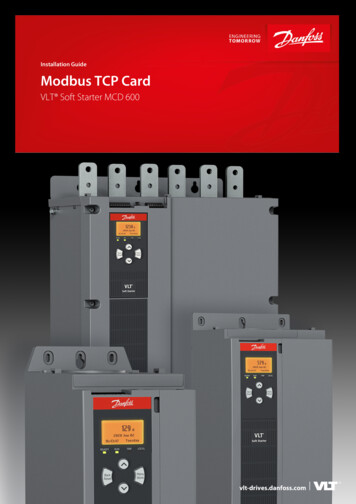
Installation3.3.3Network TerminationFor an RS-485 network it is essential to install the specified termination resistors (120W), i.e. one at both ends of anetwork segment. Failure to do so will result in signals being reflected back along the cable which will cause datacorruption.An external 120W 1/4W resistor can be connected as shown in Figure 5.12Connect todrive earth(PE)345120Ω1/4W20mmmaxFigure 5: Network Termination ResistorCMVMB401C9
Extended Parameters4Extended Parameters for Modbus RTUIn addition to the drive parameters that are detailed in the Operating Instructions (SV01), the installation of theRS485/Modbus RTU module will give access to the 400 series parameters that are exclusive to this communicationmodule. Table 4 lists these 400 Series parameters.4.1Parameter MenuTable 4: 400 Series Parameters for Modbus RTU OperationCodePossible SettingsNo.NameP400Network ProtocolDefaultIMPORTANTSelectionRS485/Modbus: Modbus Module Specific parameters0 Not Active1 Remote Keypad2 Modbus RTUP401Module RevisionP402Module Status01.0.00Display reads 01.x.x where:01 RS485/Modbus Modulex.x Module RevisionRead only0 Not Initialized1 Initialization: Module to EPM2 Initialization: EPM to Module3 OnlineRead onlyOnline state “3” indicates that the communications betweenthe drive and module are working properly.4 Failed Initialization Error5 Time-out ErrorP403P404Module ResetModule Time-outAction036 Initialization FailedModule type mismatch (P401)7 Initialization ErrorProtocol Selection mismatch (P400)0 No Action1 Reset Module parameter values to default.Returns module parameters 401 499 to the default valuesshown in this manual.0 Ignore Action to be taken in the event of a Module/Drive Timeout. Time-out is fixed at 200ms. Selection 1 (STOP) is by the method selected in P111.1 STOP (see P111)2 Quick Stop3 Fault (P405Network Fault0n)0 No Fault1 Network Time-out,P406ProprietaryP410Network address11P411NetworkBaud Rate20 2400 bpsRead only, see P425 and P426nManufacturer specificRead onlyRS485/Modbus: System bus parameters2471 4800 bps2 9600 bps3 19200 bps4 38400 bps5 57600 bps6 115200 bpsP412Network DataFormat00 8 Data bits, No Parity, 2 stop bits1 8 Data bits, No Parity, 1 stop bit2 8 Data bits, Even Parity, 1 stop bit3 8 Data bits, Odd Parity, 1 stop bit10CMVMB401CThe Drive does not support the Modbus “broadcast”function.
Extended ParametersCodePossible SettingsNo.NameDefaultP425Network Messagetime-out10.0P426Network Messagetime-out action4IMPORTANTSelection{s}0.0300.00 Not active1 STOP (see P111)2 Quick stop3 Inhibit4 Trip fault,nP427Valid NetworkmessagesReceivedP494CommunicationModule softwareversion Read onlyFormat: x.yzP495Internal Code Read onlyAlternating Display: xxx-; -yyP498Missed MessagesDrive to Module Read onlyP499Missed MessagesModule to Drive Read only00{messages}9999 Read-onlyWhen number of messages exceed 9999, counterresets to 0 and continues.RS485/Modbus: Module Specific parametersCMVMB401C11
Modbus Protocol5Modbus Protocol Details5.1Data TransmissionThis drive uses the RTU (Remote Terminal Unit) transmission mode of the Modbus Protocol and operates as a Slavedevice on the network. All devices communicating with the drive(s) must be a Modbus Master.5.2Register NumberingModbus 3X and 4X register numbers are always one greater than the actual drive register numbers. For example:drive register #24 would correspond to Modbus 3X / 4X register #25.All the register numbers referred to in this document are drive register numbers.5.3Supported Function CodesThe Modbus function codes supported by the drive are:03 - Read Holding Register (4X references)04 - Read Input Register (3X references)NOTEWe do not differentiate between 4X and 3X references. Therefore, functioncodes 03 and 04 are treated identically.Typically only one register (or one word of data) can be read at a time. Exceptions to this rule are: Register #24 (Command Frequency) can be read as a single register or as a group of 6 drive status registers(#24-29). Register #32 (low word of Total kWh) can be read as a single register or as a group of 2 registers (#32-33). Register #60 (low word of Total Runtime Hours) can be read as a single register or as a group of 2 registers(#60-61). Register #64 (low word of Total Power On Hours) can be read as a single register or as a group of 2 registers(#64-65). In some instances, multiple words can be read for a single register. When this is done for the registers below,the response from the drive will be for the number of words, rather than the number of registers, requested: Register #500 (Fault History) can be read as 1 word (returning the two most recent faults) or as 4 words (returningthe entire fault history). Register #511 (Total kWh) can be read as 1 word (returning only the low word of the 32-bit register value) oras 2 words (returning the complete 32-bit register value). Register #540 (Total Runtime Hours) can be read as 1 word (returning only the low word of the 32-bit registervalue) or as 2 words (returning the complete 32-bit register value). Register #541 (Total Power On Hours) can be read as 1 word (returning only the low word of the 32-bit registervalue) or as 2 words (returning the complete 32-bit register value).06 - Preset Single Register (4X references)Write a single register.16 - Preset Multiple Registers (4X references)While code 16 is supported it’s implementation is limited to addressing only one register per write.12CMVMB401C
Modbus Message6Modbus Message DetailsThese abbreviations will be used throughout this section to illustrate the message structure:RReadWWriteRSResponseSASlave Address (01 . F7 hex)ECException CodeRHRegister Address (high byte)RLRegister Address (low byte)DxHData (high byte)DxLData (low byte)CRCH Cyclic Redundancy Check (high byte)CRCL Cyclic Redundancy Check (low byte)6.1Register Reading6.1.1Message structure for reading one 16-bit registerAll registers except ssage structure for reading two 16-bit registersRegisters 32, 60 and 64 RCLD1H and D1L are the high and low bytes of the first 16-bit register value (32, 60, 64)D2H and D2L are the high and low bytes of the second 16-bit register value (33, 61, 65)Example: Total Run-time Hours 305419896 (12345678h)Register #60 (low word of total run-time hours) 5678hRegister #61 (high word of total run-time hours) B401CCRCL13
Modbus Message6.1.3Message structure for reading one 32-bit registerRegisters 511, 540 and 541 RCLDHH and DHL are the high and low bytes of the high word (i.e. the first 16 bits) of the 32-bit register valueDLH and DLL are the high and low bytes of the low word (i.e. the last 16 bits) of the 32-bit register valueExample: Total Run-time Hours (Register #540) 305419896 678CRCHCRCLMessage structure for reading one 4 word registerRegister 500 onlyRSA0301F40004CRCHCRCLRSSA08D1D2D3D4D5D6D7D1 holds the value of Fault 1 (the most recent fault in the fault history)D2 holds the value of Fault 2 in the fault history D8 holds Fault 8 (the oldest fault in the fault history).6.1.5Message structure for reading six 16-bit registersRegister 24 LD6HD6LCRCHCRCLRS14OperationByteRegisterCommand FrequencyD1H D1LRegister #24 (DH DL)Actual FrequencyD2H D2LRegister #25 (DH DL)LoadD3HRegister #26 (DH)Operation StatusD3LRegister #26 (DL)Rotational DirectionD4HRegister #27 (DH)Control ModeD4LRegister #27 (DL)Speed Command Source D5HRegister #28 (DH)Auto/Manual StatusD5LRegister #28 (DL)Present FaultD6HRegister #29 (DH)Command RotationD6LRegister #29 (DL)CRCHCMVMB401CCRCLD8CRCHCRCL
Modbus Message6.2Register Writing6.2.1Message structure for reading one wordAll writable HCRCLNo Response ConditionsThe drive will not respond to any m
Figure 1 illustrates the labels on the SMV RS-485 communications module. The SMVector RS-485 module is identifiable by: Two labels affixed to either side of the module. The color coded identifier label in the center of the module. A: Fieldbus Protocol B: Model Number C: Lenze Order Number D: Firmware Revision E: Hardware Revision SMV RS-485