Transcription
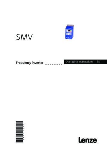
SMV(13441423)Frequency inverterOperating instructionsEN
Contents1Safety ------------------------------------ 322.12.22.3Technical ----------------------------------- 6Standards and Application -------- 6SMV Type Number ------------------ ---------------------------------------------- -- 11Dimensions and -------------------113.1.1NEMA 1 (IP31) Models 30HP al -------------------------------123.2.1Power -------------------123.2.1.1Mains Connection to 120VAC Single-Phase Supply----123.2.1.2Mains Connection to 240VAC Single-Phase Supply----133.2.1.3Mains Connection to Three-Phase Supply---------------133.2.1.4Motor -----133.2.1.5Installation Recommendations for EMC Compliance--143.2.2Fuses/Cable ------------153.2.3Control -------------------------------------------- 17Local Keypad & ------------------------17Drive Display and Modes of ------18Parameter ------------------------------19Electronic Programming Module -19Parameter -----------------------------204.5.1Basic Setup -------------204.5.2I/O Setup ----------------234.5.3Advanced Setup -------254.5.4PID ------------------------284.5.5Vector --------------------304.5.6Network -----------------324.5.7Diagnostic --------------334.5.7.1 Terminal & Protection Status Display--------------------------344.5.7.2 Keypad Status ---344.5.8Custom Modbus Instructions for ESVxxxNxxxXB571 models-----344.5.8.1Register 2000 - Drive Status Word-------------------------364.5.8.2Register 2002 - Drive egister 2003 - Drive egister 2012 - Digital ster 2100 - Network Control Word-------------------384.5.8.6Registers 2108 and 2109 - Drive Display Override-----39Status/Warning --------------------40Drive Configuration ---------------41Fault -----------------------------------42EDBSV571 EN 1.01
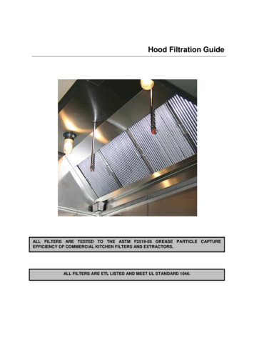
About These InstructionsThis documentation applies to the SMV frequency inverter and contains important technical data regardingthe installation, operation, and commissioning of the inverter.These instructions are only valid for SMV frequency inverters with Model Number ending in 571.Please read these instructions in their entirety before commissioning the drive.ABCDINPUT: 3 (3/PE)400/480 V2.9/2.5 A50-60 HZOUTPUT: 3 (3/PE)0 - 400/460 V2.4/2.1 A0.75 KW/1HP0 - 500 HZTYPE-4X INDOOR USE ONLYType:ESV751N 0 4TXBId-No: 00000000E FFor detailed informationrefer to instructionManual: SV01000000000000000000ESV751N0 4TXB000XX ## ##ENABCDEFCertificationsTypeInput RatingsOutput RatingsHardware VersionSoftware VersionScope of deliveryImportant 1 SMV Inverterwith EPM installed (see Section4.4) 1 Operating Instructions manualAfter receipt of the delivery, check immediately whether the items deliveredmatch the accompanying papers. Lenze AC Tech does not accept any liabilityfor deficiencies claimed subsequently.Claim: visible transport damage immediately to the forwarder. visible deficiencies /incompleteness immediately to your Lenze AC TechrepresentativeRelated DocumentsThe documentation listed herein contains information relevant to the operation of the SMVector frequency inverter. To obtainthe latest documentation, visit the Technical Library at http://www.lenzeamericas.com.Document # DescriptionCMVINS01SMVector Communications Module Installation InstructionCMVMB401SMVector ModBus RTU over RS485 Communications Reference GuideCMVLC401SMVector Lecom Communications Reference GuideCMVCAN01SMVector CANopen Communications Reference GuideCMVDVN01SMVector DeviceNet Communications Reference GuideCMVETH01SMVector EtherNet/IP Communications Reference GuideCMVPFB01SMVector PROFIBUS Communications Reference GuideALSV01SMVector Additional I/O Module Installation and Operation ManualDBV01SMVector Dynamic BrakingPTV01SMVector Potentiometer Install InstructionsRKV01SMVector ESVZXK1 Remote KeypadRKVU01SMVector ESVZXH0 Remote Keypad (for NEMA 1 15-60HP (11-45kW) Drives)Copyright 2013 - 2006 Lenze AC Tech CorporationAll rights reserved. No part of this manual may be reproduced or transmitted in any form without writtenpermission from Lenze AC Tech Corporation. The information and technical data in this manual are subjectto change without notice. Lenze AC Tech Corporation makes no warranty of any kind with respect to thismaterial, including, but not limited to, the implied warranties of its merchantability and fitness for agiven purpose. Lenze AC Tech Corporation assumes no responsibility for any errors that may appear in thismanual.All information given in this documentation has been carefully selected and tested for compliance withthe hardware and software described. Nevertheless, discrepancies cannot be ruled out. Lenze AC Tech doesnot accept any responsibility nor liability for damages that may occur. Any necessary corrections will beimplemented in subsequent editions. This document is printed in the United StatesEDBSV571 EN 1.02
Safety Information1Safety InformationGeneralSome parts of Lenze AC Tech controllers can be electrically live and some surfaces can be hot. Nonauthorized removal of the required cover, inappropriate use, and incorrect installation or operation createsthe risk of severe injury to personnel and/or damage to equipment.All operations concerning transport, installation, and commissioning as well as maintenance must becarried out by qualified, skilled personnel who are familiar with the installation, assembly, commissioning,and operation of variable frequency drives and the application for which it is being used.InstallationEnsure proper handling and avoid excessive mechanical stress. Do not bend any components and do notchange any insulation distances during transport, handling, installation or maintenance. Do not touchany electronic components or contacts. This drive contains electrostatically sensitive components, whichcan easily be damaged by inappropriate handling. Static control precautions must be adhered to duringinstallation, testing, servicing and repairing of this drive and associated options. Component damage mayresult if proper procedures are not followed.ENTo ensure proper operation, do not install the drive where it is subjected to adverse environmentalconditions such as combustible, oily, or hazardous vapors; corrosive chemicals; excessive dust, moisture orvibration; direct sunlight or extreme temperatures.This drive has been tested by Underwriters Laboratory (UL) and is UL Listed in compliance with theUL508C Safety Standard. This drive must be installed and configured in accordance with both national andinternational standards. Local codes and regulations take precedence over recommendations provided inthis and other Lenze AC Tech documentation.The SMVector drive is considered a component for integration into a machine or process. It is neither amachine nor a device ready for use in accordance with European directives (reference machinery directiveand electromagnetic compatibility directive). It is the responsibility of the end user to ensure that themachine meets the applicable standards.Electrical ConnectionWhen working on live drive controllers, applicable national safety regulations must be observed. Theelectrical installation must be carried out according to the appropriate regulations (e.g. cable cross-sections,fuses, protective earth [PE] connection). While this document does make recommendations in regards tothese items, national and local codes must be adhered to.The documentation contains information about installation in compliance with EMC (shielding, grounding,filters and cables). These notes must also be observed for CE-marked controllers. The manufacturer ofthe system or machine is responsible for compliance with the required limit values demanded by EMClegislation.ApplicationThe drive must not be used as a safety device for machines where there is a risk of personal injury ormaterial damage. Emergency Stops, over-speed protection, acceleration and deceleration limits, etc must bemade by other devices to ensure operation under all conditions.The drive does feature many protection devices that work to protect the drive and the driven equipmentby generating a fault and shutting the drive and motor down. Mains power variances can also result inshutdown of the drive. When the fault condition disappears or is cleared, the drive can be configured toautomatically restart, it is the responsibility of the user, OEM and/or integrator to ensure that the drive isconfigured for safe operation.EDBSV571 EN 1.03
Safety InformationExplosion Proof ApplicationsExplosion proof motors that are not rated for inverter use lose their certification when used for variablespeed. Due to the many areas of liability that may be encountered when dealing with these applications,the following statement of policy applies:Lenze AC Tech Corporation inverter products are sold with no warranty of fitness for a particular purposeor warranty of suitability for use with explosion proof motors. Lenze AC Tech Corporation accepts noresponsibility for any direct, incidental or consequential loss, cost or damage that may arise through the useof AC inverter products in these applications. The purchaser expressly agrees to assume all risk of any loss,cost or damage that may arise from such application.OperationENSystems including controllers must be equipped with additional monitoring and protection devicesaccording to the corresponding standards (e.g. technical equipment, regulations for prevention of accidents,etc.). The controller may be adapted to your application as described in this documentation.DANGER! After the controller has been disconnected from the supply voltage, live components and powerconnection must not be touched immediately, since capacitors could be charged. Please observethe corresponding notes on the controller. Close all protective covers and doors prior to and during operation. Do not cycle input power to the controller more than once every two minutes. For SMVector models that are equipped with a Disconnect Switch (11th character in modelnumber is L or M), the Disconnect Switch is intended as a motor service disconnect and doesnot provide branch circuit protection to the inverter or motor. When servicing the motor, it isnecessary to wait 3 minutes after turning this switch to the off position before working onmotor power wiring as the inverter stores electrical power. To service the inverter, it is necessaryto remove mains ahead of the drive and wait 3 minutes.Safety NotificationsAll safety information given in these Operating Instructions includes a visual icon, a bold signal word and adescription.Signal Word! (characterizes the severity of the danger)NOTE (describes the danger and informs on how to proceed)Icon4Signal WordMeaningConsequences if ignoredDANGER!Warns of hazardous electrical voltage.Death or severe injuries.WARNING!Warns of potential, very hazardoussituations.Risk of severe injury to personnel and/or damage to equipment.WARNING! HotSurfaceWarns of hot surface and risk of burns.Labels may be on or inside theequipment to alert people thatsurfaces may reach dangeroustemperatures.Risk of severe injury to personnel.STOP!Warns of potential damage to material and equipment.Damage to the controller/drive or itsenvironment.NOTEDesignates a general, useful note.None. If observed, then using the controller/drive system is made easier.EDBSV571 EN 1.0
Safety InformationHarmonics Notification in accordance with EN 61000-3-2, EN 61000-3-12:Operation in public supply networks (Limitation of harmonic currents i.a.w. EN 61000-3-2, ElectromagneticCompatibility (EMC) Limits). Limits for harmonic current emissions (equipment input current up to 16A/phase).DirectiveTotal Powerconnected to Mains(public supply)Additional Measures Required for Compliance (2) 0.5kWwith mains chokeEN 61000-3-20.5 . 1kWwith active filter 1kWcomplies without additional measures16 . 75ampAdditional measures are required for compliance with thestandardEN 61000-3-12EN(1) For compliance with EMC regulations, the permissable cable lengths may change.(2) The additional measures described only ensure that the controller meets the requirements of the EN61000-3-2.The machine/system manufacturer is responsible for the machine’s compliance with the regulations.Safety Information in accordance with EN 61800-5-1:DANGER! Hazard of Electrical ShockCapacitors retain charge for approximately 180 seconds after power is removed. Allow at least3 minutes for discharge of residual charge before touching the drive.WARNING! This product can cause a d.c. current in the PE conductor. Where a residual currentoperated (RCD) or monitoring (RCM) device is used for protection in case of direct orindirect contact, only an RCD or RCM Type B is allowed on the supply side of this product. Leakage Current may exceed 3.5mA AC. The minimum size of the PE conductor shallcomply with local safety regulations for high leakage current equipment. In a domestic environment, this product may cause radio interference in which casesupplementary mitigation measures may be required.NOTEControl and communications terminals provide reinforced insulation (i.e. considered SELVor PELV, providing protection in case of direct contact) when the drive is connected to apower system rated up to 300VAC between phase to ground (PE) and the applied voltage onTerminals 16 and 17 is less than 150VAC between phase to ground. Otherwise, control andcommunications terminals provide basic insulation.Safety Information in accordance with UL:Note for UL approved system with integrated controllers: UL warnings are notes which apply to UL systems.The documentation contains special information about UL.Warnings! Suitable for use on a circuit capable of delivering not more than 200,000 rmssymmetrical amperes, at the maximum voltage rating marked on the drive. Use minimum 75 C copper wire only. Shall be installed in a pollution degree 2 macro-environment. NEMA 1 (IP31) models shall be installed in a pollution degree 2 macro-environment. All models are suitable for installation in a compartment handling Conditioned Air (i.e.,plenum rated).Torque Requirements (in accordance with UL) are listed in section 3.2.1, Power Connections.EDBSV571 EN 1.05
Technical DataEN2Technical Data2.1Standards and Application ConditionsConformityCELow Voltage (2006/95/EC) & EMC (2004/108/EC) DirectivesApprovalsUL508CUnderwriters Laboratories -Power Conversion EquipmentInput voltage phase imbalance 2%Supported Power SystemsTTTNHumidity 95% non-condensingTemperature rangeInstallation heightVibration resistanceEarth leakage currentMax Permissable Cable Length (1)EnclosureProtection measures againstCompliance with EN 61000-3-2Requirements (2)Compliance with EN 61000-3-12Requirements (2) For central grounded systems, operation is permittedwithout restrictions. For corner grounded 400/500V systems, operation ispossible but reinforced insulation to control circuits iscompromised.Transport-25 70 CStorage-20 70 COperation-10 55 C (with 2.5%/ C current derating above 40 C)0 - 4000m a.m.s.l.(with 5%/1000 m current derating above 1000m a.m.s.l.)acceleration resistant up to 1.0g 3.5 mA to PE 4.0 Hp (3.0 kW)30 meters shielded, 60 meters un-shielded 5.0 Hp (3.7 kW)50 meters shielded, 100 meters un-shielded.IP31/NEMA 1IP65/NEMA 4XNEMA 1 and NEMA 4X model enclosures are plenun rated in accordance with UL508C and are suitable for installation in a compartment handling conditioned air.short circuit, earth fault, phase loss, over voltage, under voltage,motor stalling, over temperature, motor overload 0.5kWwith mains choke0.5 . 1kWwith active filter 1kWwithout additional measures16 . 75ampAdditional measures required for compliance with EN 610003-12Operation in public supply networks (Limitation of harmonic currents i.a.w. EN 61000-3-2, ElectromagneticCompatibility (EMC) Limits). Limits for harmonic current emissions (equipment input current up to 16A/phase).(1) The stated cable lengths are permissible at default carrier frequencies (refer to parameter P166).(2) The additional measures described only ensure that the controller meets the requirements of the EN61000-3-2.The machine/system manufacturer is responsible for the machine’s compliance with the regulations.6EDBSV571 EN 1.0
Technical Data2.2SMV Type Number DesignationThe table herein lists the SMVector Inverter models used in CaptiveAire systems.CaptiveAire Model #Mains VoltageHpkWESV751N01SXB571120 VAC, N06TXB571120 VAC, 1-phase240 VAC, 1- / 3-phase240 VAC, 1- / 3-phase240 VAC, 3-phase240 VAC, 1- / 3-phase240 VAC, 1- / 3-phase240 VAC, 1- / 3-phase240 VAC, 3-phase240 VAC, 3-phase240 VAC, 3-phase480/400 VAC, 3-phase480/400 VAC, 3-phase480/400 VAC, 3-phase480/400 VAC, 3-phase480/400 VAC, 3-phase480/400 VAC, 3-phase480/400 VAC, 3-phase600 VAC, 3-phase600 VAC, 3-phase600 VAC, 3-phase600 VAC, 3-phase600 VAC, 3-phase600 VAC, TEPrior to installation make sure the enclosure is suitable for the end-use environmentVariables that influence enclosure suitability include (but are not limited to)temperature, airborne contaminates, chemical concentration, mechanical stressand duration of exposure (sunlight, wind, precipitation).EDBSV571 EN 1.07
Technical Data2.3Ratings120V / 240VAC ModelsMains 120V Single Phase (1/N/PE) (90.132V), 240V Single Phase (2/PE) (170.264V); 48.62HzTypeENPowerMains CurrentOutput CurrentHeat Loss (Watts)120VA240VACont (In)AMax .06.020074NOTES:Output Current: The Output Current Maximum (%) is a percentage of the Output Current ContinuousAmps (In) rating and is adjustable in parameter P171.240VAC ModelsMains 240V Single Phase (2/PE) (170.264V); 48.62HzTypePowerMains CurrentOutput CurrentHpkW240VACont (In)AMax 13.37.0200ESV222--2S--32.217.19.6200Heat Loss (Watts)N1/IP31240V Single Phase (2/PE) (170.264V), 240V Three Phase (3/PE) (170.264V); 48.62HzType8PowerMains CurrentOutput CurrentHeat Loss (Watts)HpkW1 (2/PE)A3 (3/PE)ACont (In)AMax 2.217.110.89.6200103EDBSV571 EN 1.0
Technical Data240V Three Phase (3/PE) (170.264V); 48.62HzTypePowerHpMains CurrentkWOutput Current240VACont (In)AMax I%Heat Loss 225ESV752--2T--107.53329200274ENNOTES:Output Current: The Output Current Maximum (%) is a percentage of the Output Current ContinuousAmps (In) rating and is adjustable in parameter P171.400.480VAC Models400 . 480V Three Phase (3/PE) (400V: 340.440V), (480V: 340.528V); 48.62HzTypePowerMains Current480VAOutput CurrentCont (In)AHeat Loss (Watts)HpkW400VAMax 0175200208400V 480VNOTES:Output Current: The Output Current Maximum (%) is a percentage of the Output Current ContinuousAmps (In) rating and is adjustable in parameter P171.For 400.480 VAC models, the output current maximum (%) in the 400V column is used when P107 0For 400.480 VAC models, the output current maximum (%) in the 480V column is used when P107 1EDBSV571 EN 1.09
Technical Data600VAC Models600V Three Phase (3/PE) (425.660V); 48.62HzTypeENPowerMains CurrentHpkWOutput CurrentHeat Loss (Watts)Max I%N1/IP31ACont --107.512.411200172NOTES:Output Current: The Output Current Maximum (%) is a percentage of the Output Current ContinuousAmps (In) rating and is adjustable in parameter P171.STOP! For installations above 1000m a.m.s.l., derate In by 5% per 1000m, donot exceed 4000m a.m.s.l. Operation above 40 C, derate In by 2.5% per C, do not exceed 55 C.Output Current (In) derating for Carrier Frequency (P166) for NEMA 1(IP31) Models:- If P166 2 (8 kHz), derate In to 92% of drive rating- If P166 3 (10 kHz), derate In to 84% of drive ratingOutput Current (In) derating for Carrier Frequency (P166) for NEMA 4X(IP65) Models:- If P166 1 (6 kHz), derate In to 92% of drive rating- If P166 2 (8 kHz), derate In to 84% of drive rating- If P166 3 (10 kHz), derate In to 76% of drive rating10EDBSV571 EN 1.0
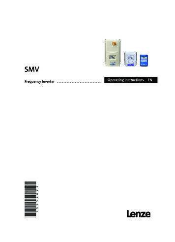
Installation3Installation3.1Dimensions and MountingWARNING!Drives must not be installed where subjected to adverse environmental conditions such as:combustible, oily, or hazardous vapors; corrosive chemicals; excessive dust, moisture or vibration;direct sunlight or extreme temperatures.3.1.1NEMA 1 (IP31) Models 30HP (22kW)b2s2cENMounting Screws4 x #1018 lb-in4 x M520 Nm()b1bs1a1s1s2aain (mm)a1in (mm)bin (mm)b1in (mm)b2in (mm)cin (mm)s1in (mm)s2in (mm)mlb (kg)3.90 (99)3.12 (79)7.48 (190)7.00 (178)0.24 (6)4.35 (111)0.6 (15)2.0 (50)2.0 (0.9)3.90 (99)3.12 (79)7.52 (191)7.00 (178)0.26 (7)5.45 (138)0.6 (15)2.0 (50)2.8 (1.3)G3 ESV402 B3.90 (99)3.12 (79)7.52 (191)7.00 (178)0.30 (8)5.80 (147)0.6 (15)2.0 (50)3.2 (1.5)ESV552 B;ESV752 B5.12 (130)4.25 (108)9.83 (250)9.30 (236)0.26 (7)6.30 (160)0.6 (15)2.0 (50)6.0 (2.0)ESV113 B;ESV153 BJ1ESV183 B;ESV223 B6.92 (176)5.75 (146) 12.50 (318) 11.88 (302)0.31 (8)8.09 (205)0.6 (15)2.0 (50)13.55 (6.15)TypeESV251 B;G1 ESV371 BESV751 BESV112 B;G2 ESV152 BESV222 BH1Conduit Hole DimensionsQP1TypeNin (mm)Pin (mm)P1in (mm)Qin (mm)Sin (mm)G11.84 (47)1.93 (49).70 (18)1.00 (25).88 (22)G21.84 (47)3.03 (77).70 (18)1.00 (25).88 (22)G31.84 (47)3.38 (86).70 (18)1.00 (25)QSPNEDBSV571 EN 1.0H12.46 (62)3.55 (90).13 (3)1.38 (35)J13.32 (84)4.62 (117).73 (19)1.40 (36).88 (22)1.13 (29).88 (22)1.31 (33).88 (22)11
Installation3.2Electrical InstallationInstallation After a Long Period of StorageSTOP!Severe damage to the drive can result if it is operated after a long period of storage orinactivity without reforming the DC bus capacitors.If input power has not been applied to the drive for a period of time exceeding threeyears (due to storage, etc), the electrolytic DC bus capacitors within the drive can changeinternally, resulting in excessive leakage current. This can result in premature failure of thecapacitors if the drive is operated after such a long period of inactivity or storage.ENIn order to reform the capacitors and prepare the drive for operation after a long period ofinactivity, apply input power to the drive for 8 hours prior to actually operating the motor.3.2.1Power ConnectionsSTOP!If the kVA rating of the AC supply transformer is greater than 10 times the input kVA ratingof the drive(s), an isolation transformer or 2-3% input line reactor must be added to theline side of the drive(s).DANGER! Hazard of electrical shock!Circuit potentials up to 600 VAC are possible. Capacitors retain charge after power isremoved. Disconnect power and wait at least three minutes before servicing the drive.STOP! Verify mains voltage before connecting to drive. Do not connect mains power to the output terminals (U,V,W)! Severe damage to thedrive will result. Do not cycle mains power more than once every two minutes. Damage to the drive mayresult.Mains and Motor Terminations3.2.1.1ESV.N01S.TypeTorqueStrip Length 5HP12 lb-in (1.3 Nm)5/16 in(8mm)ESV552xx2T, ESV752xx2T, ESV113xx4/6, ESV153xx4/6, ESV183xx6,ESV223xx616 lb-in (1.8 Nm)5/16 in(8mm)ESV552xx4Txx, ESV752xx4Txx, ESV552xx6Txx, ESV752xx6Txx12 lb-in (1.3Nm)0.25 in (6mm)ESV113xx2xxx, ESV153xx2xxx, ESV183xx4xxx, ESV223xx4xxx,ESV303xx4xxx24 lb-in (2.7 Nm)7/16 in(10mm)ESV373xx4xxx, ESV453xx4xxx27 lb-in (3.05 Nm)0.75 in(19mm)Mains Connection to 120VAC Single-Phase SupplyPE L1 L2 NPE12L1NEDBSV571 EN 1.0
Installation3.2.1.2Mains Connection to 240VAC Single-Phase SupplyPE L1 L2 NPE L1 L2 NESV.N01S.ESV.N01S.PEL1L2PEPE L1 L2 L3ESV.N02Y.(1/N/PE AC)PEL1L2PEPE L1 L2L1NENPE L1 L2ESV.N02S.(1/N/PE AC)ESV.N02S.(2/PE AC)PEL1L2PEL1NMains Connection to Three-Phase SupplyESV.N02Y.ESV.N02T.ESV.N04T.ESV.N06T.(3/PE AC)PE L1 L2 L3PE3.2.1.4L1L2L3Motor ConnectionU/T1 V/T2 W/T3 PEWARNING!PESPESPEPESPESPESNPE L1 L2 L3ESV.N02Y.(2/PE AC)3.2.1.3L1M3 If the cable connection between the drive and the motor has anin-line contactor or circuit breaker then the drive must be stoppedprior to opening/closing the contacts. Failure to do so may result in0vercurrent trips and/or damage to the inverter.WARNING!PEPES Protective EarthShieldingLeakage current may exceed 3.5 mA AC. The minimum size ofthe protective earth (PE) conductor shall comply with local safetyregulations for high leakage current equipment.STOP!In the case of a Spinning Motor:To bring free-wheeling loads such as fans to a rest before starting the drive, usethe DC injection braking function. Starting a drive into a freewheeling motorcreates a direct short-circuit and may result in damage to the drive.Confirm motor suitability for use with DC injection braking.Consult parameter P110 for starting / restarting into spinning motors.EDBSV571 EN 1.013
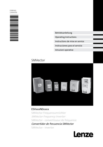
Installation3.2.1.5Installation Recommendations for EMC ComplianceFor compliance with EN 61800-3 or other EMC standards, motor cables, line cables and control orcommunications cables must be shielded with each shield/screen clamped to the drive chassis. This clampis typically located at the conduit mounting plate.The EMC requirements apply to the final installation in its entirety, not to the individual components used.Because every installation is different, the recommended installation should follow these guidelines asa minimum. Additional equipment (such as ferrite core absorbers on power conductors) or alternativepractices may be required to meet conformance in some installations.ENMotor cable should below capacitance (core/core 75pF/m, core/shield 150pF/m). Filtered drivescan meet the class A limitsof EN 55011 and EN 61800-3Category 2 with this type ofmotor cable up to 10 meters.NOTE: Refer to AppendixA for recommended cablelengths. Any externalline filter should have itschassis connected to thedrive chassis by mountinghardware or with theshortest possible wire orbraid.14Enclosure / BackplateExternalControlCircuitsControl and signal cablingshould be separated frompower cables bya minimum of 300mmFromAC Supply360 shield termination tobackplate using saddle clampFromMotorScreened motor cable:core/core 75pF/Mcore/shield 150pF/MEDBSV571 EN 1.0
Installation3.2.2Fuses/Cable Cross-SectionsNOTE: Observe local regulations. Local codes may supersede these recommendationsWARNING: Per UL, use a FUSE for 240V drives requiring 40A protection and for 400/480/600V drives requiring 32A protection.Recommendations120V1 (1/N/PE)240V1 (2/PE)240V3 (3/PE)400Vor 480V3 (3/PE)600V3 (3/PE)Input Power Wiring(L1, L2, L3, N01SXBM10 AC10 A10 A10 A1.514ESV371N01SXBM16 AC16 A15 A15 A2.514ESV751N01SXBM25 AC25 A25 A25 A410ESV112N01SXBESV251N01SXB, ESV251N02SXB,ESV371N01SXB, ESV371N02YXBESV751N01SXB, ESV751N02YXBM32 AC32 A30A30A410M10 AC10 A10 A10 A1.514M16 AC16 A15 A15 A2.514ESV112N02YXB, ESV112N01SXBM20 AC20 A20 A20 A2.512ESV152N02YXBM25 AC25 A25 A25 A2.512ESV222N02YXBM32 AC32A30 A30 A410ESV371N02YXB, ESV751N02YXBESV112N02YXB, ESV152N02YXB,ESV112N02TXB, ESV152N0
ALSV01 SMVector Additional I/O Module Installation and Operation Manual DBV01 SMVector Dynamic Braking PTV01 SMVector Potentiometer Install Instructions RKV01 SMVector ESVZXK1 Remote Keypad . this and other Lenze AC Tech documentation. The SMVector drive is considered a component for integration into a machine or process. It is neither a