Transcription
SMVector Additional I/O ModuleInstallation and Operation Manual
About These InstructionsThis documentation applies to the optional Additional I/O module for the SMVector inverter and should be usedin conjunction with the SMVector Operating Instructions (Document SV01) that shipped with the drive. Thesedocuments should be read in their entirety as they contain important technical data and describe the installationand operation of the drive.NOTETo use the I/O Module with SMVector drives rated at 0.33 to 10 HP (0.25 to 7.5 kW) requiresthat the drive has software version 3.0 or higher. The software version can be found inthe SMVector drive diagnostic parameter P501. To use the I/O Module options the valuedisplayed in P501 must be 3.00 or higher.SMVector drives rated at 15 HP (11.0 kW) and higher all support the I/O options models sothere is no need to verify the value in P501. 2008 Lenze AC Tech CorporationNo part of this documentation may be copied or made available to third parties without the explicit written approvalof Lenze AC Tech Corporation. All information given in this documentation has been carefully selected and testedfor compliance with the hardware and software described. Nevertheless, discrepancies cannot be ruled out. LenzeAC Tech does not accept any responsibility nor liability for damages that may occur. Any necessary corrections willbe implemented in subsequent editions.
Contents1Safety Information.11.1234Warnings, Cautions and lation.11.1.4Electrical e Overview.32.2Module Specification.32.3Module Identification Label.3Installation.43.1Mechanical Installation.43.2Module Terminal Block.53.3Electrical Installation.63.3.1Terminal Description.63.3.2Module Wiring.6Commissioning.74.1Network Parameters (P400).74.2Additional I/O Module Parameters.84.3Display.10iALSV01B
Safety Information1Safety Information1.1Warnings, Cautions and Notes1.1.1GeneralSome parts of Lenze controllers (frequency inverters, servo inverters, DC controllers) can be live, movingand rotating. Some surfaces can be hot.Non-authorized removal of the required cover, inappropriate use, and incorrect installation or operationcreates the risk of severe injury to personnel or damage to equipment.All operations concerning transport, installation, and commissioning as well as maintenance must becarried out by qualified, skilled personnel (IEC 364 and CENELEC HD 384 or DIN VDE 0100 and IEC report664 or DIN VDE0110 and national regulations for the prevention of accidents must be observed).According to this basic safety information, qualified skilled personnel are persons who are familiar withthe installation, assembly, commissioning, and operation of the product and who have the qualificationsnecessary for their occupation.1.1.2ApplicationDrive controllers are components designed for installation in electrical systems or machinery. They arenot to be used as appliances. They are intended exclusively for professional and commercial purposesaccording to EN 61000-3-2. The documentation includes information on compliance with EN 61000-3-2.When installing the drive controllers in machines, commissioning (i.e. the starting of operation as directed)is prohibited until it is proven that the machine complies with the regulations of the EC Directive 2006/42/EC (Machinery Directive); EN 60204 must be observed.Commissioning (i.e. starting drive as directed) is only allowed when there is compliance to the EMCDirective (2004/108/EC).The drive controllers meet the requirements of the Low Voltage Directive 2006/95/EC. The harmonisedstandards of the series EN 50178/DIN VDE 0160 apply to the controllers.The availability of controllers is restricted according to EN 61800-3. These products can causeradio interference in residential areas. In the case of radio interference, special measures may benecessary for drive controllers.1.1.3InstallationEnsure proper handling and avoid excessive mechanical stress. Do not bend any components and do notchange any insulation distances during transport or handling. Do not touch any electronic componentsand contacts. Controllers contain electrostatically sensitive components, which can easily be damaged byinappropriate handling. Do not damage or destroy any electrical components since this might endangeryour health! When installing the drive ensure optimal airflow by observing all clearance distances in thedrive's user manual. Do not expose the drive to excessive: vibration, temperature, humidity, sunlight, dust,pollutants, corrosive chemicals or other hazardous environments.1ALSV01B
Safety Information1.1.4Electrical ConnectionWhen working on live drive controllers, applicable national regulations for the prevention of accidents (e.g.VBG 4) must be observed.The electrical installation must be carried out in accordance with the appropriate regulations (e.g.cable cross-sections, fuses, PE connection). Additional information can be obtained from the regulatorydocumentation.The regulatory documentation contains information about installation in compliance with EMC (shielding,grounding, filters and cables). These notes must also be observed for CE-marked controllers.The manufacturer of the system or machine is responsible for compliance with the required limit valuesdemanded by EMC legislation.1.1.5OperationSystems including controllers must be equipped with additional monitoring and protection devices accordingto the corresponding standards (e.g. technical equipment, regulations for prevention of accidents, etc.).You are allowed to adapt the controller to your application as described in the documentation.DANGER! After the controller has been disconnected from the supply voltage, do not touch the livecomponents and power connection until the capacitors have discharged. Please observethe corresponding notes on the controller. Do not continuously cycle input power to the controller more than once every three minutes. Close all protective covers and doors during operation.WARNING!Network control permits automatic starting and stopping of the inverter drive. The system designmust incorporate adequate protection to prevent personnel from accessing moving equipmentwhile power is applied to the drive system.Table 1: Pictographs used in these instructionsPictographALSV01BSignal wordMeaningConsequences if ignoredDANGER!Warning of Hazardous ElectricalVoltage.Reference to an imminent dangerthat may result in death or seriouspersonal injury if the correspondingmeasures are not taken.WARNING!Impending or possible dangerfor personsDeath or injurySTOP!Possible damage to equipmentDamage to drive system or itssurroundingsNOTEUseful tip: If observed, it willmake using the drive easier2
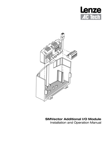
Introduction2IntroductionThis manual provides installation and operational data specific to the Additional I/O Module for the SMVectorseries inverters. This manual is a supplement (not a substitution for) the standard SMVector - FrequencyInverter Operating Instructions (document number SV01).This document assumes that the reader has a working knowledge of the standard SMVector FrequencyInverter and has familiarity with the programming and operation of the SMVector Frequency Inverter. Pleaseconsult the SMVector - Frequency Inverter Operating Instructions (SV01) for more details.2.1Module OverviewThe Additional I/O Module is available in two configurations (ESVZAL0, ESVZAL1) for use with the SMVectorFrequency Inverter. The modules are intended to supplement the standard I/O functions available in theSMVector inverter.The I/O module fits into the SMVector inverter terminal cover. This allows for easy field installation anddoes not add to the overall size of the SMVector inverter.SMVector inverters that are fitted with an additional I/O module option will no longer have the capability ofaccommodating an optional communication module.2.2Module Specification 2.3P/N ESVZAL0: 1 programmable form C relay output.P/N ESVZAL1: 1 programmable form C relay output and 2 programmable digital inputs.Module Identification LabelFigure 1 illustrates the labels on the SMV Additional I/O Module. The SMVector Additional I/O Module isidentifiable by: Label affixed to side of the module.Part Number ESVZALx on module label.Right-hand Label:Ratings & CertificationsAdditional I/O ONLYS/N: 123456789LISTEDLeft-hand Label:Module DataSMV I/OTYPE: ESVZAL1ID-NO: 12345678ESVZAL1-000XX1A10ABCDEA: Module TypeB: Model NumberC: Lenze Order NumberD: Firmware RevisionE: Hardware RevisionFigure 1: Additional I/O Module Label3ALSV01B
Installation3Installation3.1Mechanical Installation1. Ensure that for safety reasons the AC supply has been disconnected before opening the terminalcover.2. Insert the Additional I/O module in the terminal cover and securely “click” into position as illustratedin Figure 2.3. Wire the cables to the connector provided and plug the connector into the option module.4. Align terminal cover for re-fitting, connect the module umbilical cord to the drive then close the coverand secure, as shown in Figure 3.0.5 Nm/ 4.5 lb-in 2.8 mm²(12-22 AWG)7mm0.5 Nm/ 4.5 lb-in13G13F2120 2.8 mm²(12-22 AWG)7mm1913G13F2120Red wire and black wireare present in the ESVZAL1module. They are notpresent in the ESVZAL0module. Refer to wiringinstructions below.Figure 2a: NEMA 1 (IP31) InstallationFigure 2b: NEMA 4X (IP65) InstallationThe ESVZAL1 I/O Option Modulecontains 1 red wire and 1 black wirethat must be wired into the standardSMVector Inverter terminal strip.Terminal Strip of Standard SMVector Inverter125625 4 11 13A 13B 13C 14 30 16 17Connect the black wire to terminal #2.Connect the red wire to terminal #11.Refer to adjacent diagram.Black and Red wires from ESVZAL1 ModuleFigure 2c: Wiring the ESVZAL1 I/O ModuleALSV01B419
InstallationFigure 3: Re-Installing the Terminal Cover3.2Module Terminal BlockTable 2 identifies the terminals and describes the function of each. Figure 4 illustrates the Additional I/O 5pole 5mm pluggable connector.Table 2: Additional I/O TerminalsTerminalFunction19Relay N.O.Description20Relay Common21Relay N.C.13FDigital InputAvailable only on ESVZAL113GDigital InputAvailable only on ESVZAL119202113F13GFigure 4: Additional I/O Connector5ALSV01B
Installation3.3Electrical Installation3.3.1Terminal DescriptionTable 3 contains each terminal's electrical specification and any parameter description associated withthat terminal.Table 3: Additional I/O Module SpecificationsTerminalFunctionDescription19Relay N.O.20Relay CommonRelay output configurable with P441, P144AC 250 V / 3 A 17 DC 24 V / 2 A 240 V / 0.22 A, non-inductive21Relay N.C.13FDigital Input13GDigital Input13F configurable with P42613G configurable with P427Input Impedance 4.3 kohmThe assertion level of Terminals 13F and 13G will match the assertion level ofthe standard SMVector digital inputs 13A, 13B, 13C, etc Refer to the description of P120 and Terminal #4 in the SMVector - FrequencyInverter Operating Instructions (SV01)NOTEFor ESVZAL0:Control and communications terminals provide reinforced insulation when the drive is connected to a power systemrated up to 300V between phase to ground (PE) and the applied voltage on terminals 19, 20 and 21 is less than 250VAC between phase and ground (PE)For ESVZAL1:Control and communications terminals provide reinforced insulation when the drive is connected to a power systemrated up to 300V between phase to ground (PE) and the applied voltage on terminals 19, 20 and 21 is less than 150VAC between phase and ground (PE)Control and communications terminals provide basic insulation when the drive is connected to a power systemrated up to 300V between phase to ground (PE) and the applied voltage on terminals 19, 20 and 21 is less than 250VAC between phase and ground (PE).3.3.2Module WiringFigure 5 illustrates the wiring of the ESVZAL0 and ESVZAL1 modules.192021192021 13F 13GTo SMVector ControlTerminal Strip TB#4Figure 5a: ESVZAL0Figure 5b: ESVZAL1NOTETo assert terminals 13F and 13G with external powersources, refer to section 3.2.3 of the SMVectorOperating Instructions (SV01)ALSV01B6
Commissioning4Commissioning4.1Network Parameters (P400)CodeNo.NamePossible SettingsDefault Selectionp400 Network ProtocolIMPORTANT0 Not ActiveThis parameter setting is based upon thenetwork or I/O module that is installed.1 Remote Keypad2 Modbus RTU3 CANopen4 DeviceNet5 Ethernet6 Profibus7 Lecom-B8 I/O Modulep401 Module Type Installed00 No Module Installed1 Basic I/O (0x0100, 1.0.0)2 RS485/Rem. Keypad (0x0200, 2.0.0)3 CANopen (0x0300, 3.0.0)Module type format: 0xAABC; Drive Display:AA.B.CAA Module TypeB Major revisionC minor revision11 PROFIBUS (0x1100, 11.0.0)12 Ethernet (0x1200, 12.0.0)P402Module Status00 Not Initialized1 Initialization: Module to EPM2 Initialization: EPM to Module3 Online4 Failed Initialization Error5 Time-out ErrorP403Module Reset06 Initialization FailedModule type mismatch P4017 Initialization ErrorProtocol selection mismatch P4000 No ActionReturns module parameters 401 499 to thedefault values shown in the manual1 Reset parameters to default valuesP404Module Timeout Action00 No FaultAction to be taken in the event of a Module/Drive Time-out.Time is fixed at 200msSTOP is by the method selected in P111.1 STOP (see P111)2 Quick Stop3 Fault (F ntF)P405Current Network Fault0 No Fault1 F.nF1NetIdle Mode2 F.nF2Loss of Ethernet I/O connection3 F.nF3Network Fault4 F.nF4Explicit Message Timeout5 F.nF5Overall Network Timeout6 F.nF6Overall Explicit Timeout7 F.nF7P406Overall I/O Message TimeoutProprietaryp407 P499Manufacturer specificRefer to the Communications Reference Guidespecific to the network or I/O module installed.Module Specific ParametersNOTESet P400 8 for the SMVector drive to communicate with the additional I/O module.7ALSV01B
Commissioning4.2Additional I/O Module ParametersIn addition to the parameters detailed in the SMVector Frequency Inverter Operating Instructions (SV01),installing the Additional I/O Module provides access to supplementary parameters exclusive to the AdditionalI/O Module. Table 4 lists these supplementary parameters.Table 4: Additional I/O Module ParametersCodeNo.NameP426 TB-13F InputFunctionp427 TB-13G InputFunctionPossible SettingsDefault Selection0None01AUTO Reference: 0-10 VDC2AUTO Reference: 4-20 mARESERVED4AUTO Reference: MOP Up5AUTO Reference: MOP Down678AUTO Reference: KeypadAUTO Reference: NetworkControl Select910111213141516Network EnableReverse RotationStart ForwardStart ReverseRun ForwardRun ReverseJog ForwardJog Reverse171819Accel/Decel #2DC BrakeAuxiliary Ramp to Stop202122Clear FaultExternal Fault F.EFInverse External Fault F.EFIMPORTANTDisables inputFor frequency mode, see P160.P161,For PID mode, see P204 P205,For vector torque mode, see P330 Normally open: Close input to increase or decreasespeed, PID setpoint or torque setpoint. MOP Up is not active while in STOPUse when P100 4, 5 to switch between terminal stripcontrol and local or remote keypad control.Required to start the drive through the network.Open ForwardClosed ReverseRefer to Note for typical circuitRefer to Note for typical circuitJog Forward speed P134Jog Reverse speed P135Active even if P112 0Refer to P125, P126Refer to P174; close input to override P175Normally closed: Opening input will ramp drive to STOPaccording to P127, even if P111 is set to Coast (0 or 1).Close to reset faultNormally closed circuit; open to tripNormally open circuit; close to tripWARNING!Jog overrides all STOP commands! To stop the drive while in Jog mode, the Jog input must be deactivated or a fault condition induced.NOTE When input is activated, settings 1.7 override P101 When TB-13A to TB-13D; TB-13F and TB-13G are configured for Auto References other than MOP, TB-13G overrides TB-13F, TB-13Foverrides TB-13D, TB-13D overrides TB-13C, TB-13C overrides TB-13B and TB-13B overrides TB-13A. Any other Auto Reference willhave priority over MOP. Settings 10.14 are only valid in Terminal Strip mode (P100 1, 4, 5, 6) If Start/Run/Jog Forward and Start/Run/Jog Reverse are both activated, drive will STOP If Jog input is activated while the drive is running, the drive will enter Jog mode; when Jog input is deactivated, drive will STOP An F.AL fault will occur if the Assertion Level switch (ALsw) position does not match the P120 setting and any of the digital inputs(P121.P124, P426 . P427) are set to a value other than 0. An F.IL fault will occur under the following conditions:- TB-13A.TB-13D and TB-13F.TB-13G settings are duplicated (each setting, except 0 and 3, can only be used once)- One input is set to “MOP Up” and another is not set to “MOP Down”, or vice-versa.- One input is set to 10 and another input is set to 11 14.- One input is set to 11 or 12 and another input is set for 13 or 14. TB-13D and P124 exist in 15HP (11kW) and greater drives onlyALSV01B8
CommissioningCodeNo.Namep441 Relay OutputTB-19, 20, 21P144 Digital OutputInversionPossible SettingsDefault Selection00NoneIMPORTANTDisables the output1RunEnergizes when the drive is running2ReverseEnergizes when reverse rotation is active3FaultDe-energizes when the drive trips, or power is removed4Inverse FaultEnergizes when the drive trips5Fault LockoutP110 3.6: De-energizes if all restart attempts fail6At SpeedEnergizes when output frequency commanded frequency7Above Preset Speed #6Energizes when output frequency P1368Current LimitEnergizes when motor current P1719Follower Loss (4-20 mA)Energizes when 4-20 mA signal falls below 2 mA10Loss of LoadEnergizes when motor load drops below P145; Refer toP146 also11Local Keypad Control Active12Terminal Strip Control Active13Remote Keypad Control Active14Network Control Active15Standard Reference ActiveEnergizes when P101 reference is active16Auto Reference ActiveEnergizes when Auto Reference is activated using TB-13input; refer to P121.P12417Sleep Mode ActiveRefer to P240.P24218PID Feedback Min. AlarmEnergizes when PID feedback signal P21419Inverse PID Feedback Min. AlarmDe-energizes when PID feedback signal P21420PID Feedback Max AlarmEnergizes when PID feedback signal P21521Inverse PID Feedback Max AlarmDe-energizes when PID feedback signal P21522PID Feedback withinMin/Max Alarm rangeEnergizes when PID feedback signal is within the Min/MaxAlarm range; refer to P214, P21523PID Feedback outsideMin/Max Alarm rangeEnergizes when PID feedback signal is outside the Min/MaxAlarm range; refer to P214, P21524Reserved25Network ActivatedRequires 15HP (11kW) or higher drive.No function for 0.33-10HP (0.25kW-7.5kW) drives.26Loss of 0-10V InputEnergizes when 0-10V signal P15827Sequencer ControlledState set in individual sequencer segments28Sequencer Active29Sequencer Suspended30Sequence Done31Output Frequency rgizes when the selected source is active for startcontrolEnd sequenceInvertP142NONOYESYESNONOYESYESOutput inactiveInvertP140NOYESNOYESNOYESNOYESUsed to invert the selections for P140, P441 (Relay Output)and P142 (TB-14 Output).EXAMPLE: When P140 6 (AT SPEED), the relay isenergized when output frequency commandedfrequency. IF P144 1, 3, 5 or 7, then P140 is inverted(INVERSE AT SPEED) and the relay is energized when theoutput frequency does not equal the command frequency.NOTEInverting P140, P142 or P441 when the parameter is set to NONE (0) will result in the output beingenergized continuously.9ALSV01B
Commissioning4.3DisplayParameter P530 allows monitoring of the control terminal points and common drive conditions.An illuminated LED segment indicates: the protective circuit is active (LED 1) the Logic Assertion Switch is set to High ( ) input terminal is asserted (LED 2) output terminal is energized (LED 4) the Charge Relay is not a terminal, this segment will be illuminated when the Charge Relay is energized(LED 4).LED #12Current Limit DiagnosticLogic Assertion SwitchInput 1Input 13BRelayOutput 14Input 13D*34ChargeRelayAdditional I/O Module onlyInput 13CInput 13AFactory ReservedProtective DiagnosticAuxiliary RelayInput 13FInput 13E* Input 13D available on 15-60HP (11-45kW) models onlyFigure 6: Status IndicatorsALSV01B10
Lenze AC Tech Corporation630 Douglas Street Uxbridge MA 01569 USASales: 800-217-9100 Service: 508-278-9100www.lenzeamericas.comSMVector Additional I/O ModuleInstallation & Operation Manual (ALSV01B-en2)(13376253)
SMVector inverter. The I/O module fits into the SMVector inverter terminal cover. This allows for easy field installation and does not add to the overall size of the SMVector inverter. SMVector inverters that are fitted with an additional I/O module option will no longer have the capability of accommodating an optional communication module.