Transcription
Session #:INCORPORATING SYSTEMS ENGINEERING INTO THE SENIOR DESIGN –AUTONOMOUS LAWN MOWING MACHINEGuoping Wang, and Zhuming BiIndiana University Purdue University Fort Wayne, Fort Wayne, Indiana;Email: wang@engr.ipfw.edu and bi@engr.ipfw.edu1.INTRODUCTIONSystems Engineering is an interdisciplinary process that ensures the satisfaction of customer'sneeds throughout a system's entire life cycle. The purpose of systems engineering is to producesystems that satisfy the customers' needs, increase the probability of system success, reduce riskand the total life-cycle cost. This process consists of seven tasks with the acronym SIMILAR(Bahill, 1998) as shown in Figure 1.Figure 1. The Systems Engineering Process1.1 State the Problem.Stating the problem is the most important systems engineering task. It entails identifyingcustomers, understanding customer needs, establishing the need for change, discoveringrequirements and defining system functions.The problem statement starts with a description of the top-level function which the system mustperform or the deficiency that must be ameliorated. It includes system requirements stated interms of what must be done, not how to do it. It might be composed in words or as a model.Inputs come from end users, operators, bill payers, owners, regulatory agencies, victims,sponsors, marketing, manufacturing, etc. These are called stakeholders. Identifying thestakeholders is an important initial task. In a modern business environment, the problemstatement starts with a reason for change followed by vision and mission statements for thecompany. The problem statement is one of Systems Engineering's most important products. Anelegant solution to the wrong problem is less than worthless.American Society for Engineering EducationMarch 17, 2012 – Valparaiso University, Valparaiso, Indiana.2012 IL/IN Sectional Conference
1.2. Investigate alternatives.Alternatives are investigated and evaluated based on performance, cost and risk.Alternative designs are evaluated based on performance, cost, schedule and risk criteria. Nodesign is likely to be best on all criteria, so multi-criteria decision aiding techniques should beused to reveal the preferred alternatives. This analysis should be redone whenever more data areavailable. For example, criteria should be computed initially based on estimates by the designengineers. Then models should be constructed and evaluated. Next simulation data should bederived. Subsequently prototypes should be measured and finally tests should be run on the realsystem. For the design of complex systems, study of alternative designs reduces project risk.Investigating bizarre alternatives helps clarify the problem statement. This is one of the mainprocesses used to define system architecture.1.3 Model the system.Running models clarifies requirements, reveals bottlenecks and fragmented activities, reducescost and exposes duplication of efforts.Models will be developed for most alternative designs. The model for the preferred alternativewill be expanded and used to help manage the system throughout its entire life cycle. Many typesof system models are used, such as physical analogies, analytic equations, state machines, blockdiagrams, functional flow diagrams, object-oriented models, computer simulations and mentalmodels. Systems Engineering is responsible for creating a product and also a process forproducing it. So, models should be constructed for both the product and the process. Processmodels allow us, for example, to study scheduling changes, create dynamic PERT charts andperform sensitivity analyses to show the effects of delaying or accelerating certain subprojects.Running the process models reveals bottlenecks and fragmented activities, reduces cost andexposes duplication of effort. Product models help explain the system. These models are alsoused in trade-off studies and risk management.1.4. Integrate.Integration means designing interfaces and bringing system elements together so they work as awhole. This requires extensive communication and coordination.Integration means bringing things together so they work as a whole. System integration meansbringing subsystems together to produce the desired result and ensure that the subsystems willinteract to satisfy the customer's needs. End users and engineers need to be taught to use thesystem with courses, manuals and training on the prototypes.1.5 Launch the system.Launching the system means running the system and producing outputs -- making the system dowhat it was intended to do.American Society for Engineering EducationMarch 17, 2012 – Valparaiso University, Valparaiso, Indiana.2012 IL/IN Sectional Conference
Configuration management (also called modification management) ensures that any changes inrequirements, design or implementation are controlled, carefully identified, and accuratelyrecorded. All stakeholders should have an opportunity to comment on proposed changes.Decisions to adopt a change must be captured in a baseline database. This baseline is a timefrozen design containing requirements for functions, performance, interfaces, verification,testing, cost, etc. Baselines can only be changed at specified points in the life cycle. Allconcerned parties must be notified of changes to ensure that they are all working on the samedesign.1.6 Assess performance.Performance is assessed using evaluation criteria, technical performance measures and measures-- measurement is the key. If you cannot measure it, you cannot control it. If you cannot controlit, you cannot improve it.During the operation and maintenance phase of the system life cycle the performance of thesystem must be measured. Initially these measurements will be used to verify that the system isin compliance with its requirements. Later they will be used to detect deterioration and initiatemaintenance.1.7 Re-evaluation.Re-evaluation should be a continual and iterative process with many parallel loops.Re-evaluation is arguably the most important task of Systems Engineering. For centuriesengineers have used feedback to control systems and improve performance. It is one of the mostfundamental engineering tools. Re-evaluation means observing outputs and using thisinformation to modify the system inputs, the product or the process. Re-evaluation should be acontinual process with many parallel loops. Everyone should continually re-evaluate the systemlooking for ways to improve quality.In the Department of Engineering at Indiana University Purdue University Fort Wayne, theCapstone Senior Design (SD) spans two semesters. In the first semester, students write theproblem statements which include system requirements, specification, and design variables,brainstorming various design options, generate concept designs, evaluate the conceptual designsand finish their detailed design. In the second semester, students implement and build theirdetailed design, test and evaluate their prototype. Besides the assessments from IndustrialSponsors, faculty members, enrolled students, SD course coordinators and Senior Design facultyadvisors, several Systems Engineering reviews are also conducted, which include SystemRequirement Review (SRR), Preliminary Design Review (PDR) and Critical Design Review(CDR). The SD process is shown in Figure 2.American Society for Engineering EducationMarch 17, 2012 – Valparaiso University, Valparaiso, Indiana.2012 IL/IN Sectional Conference
Figure 2. Senior Design Process at IPFWIn this paper, the SD experience integration with Systems Engineering in one project –Autonomous Lawn Mowing Machine is presented. This approach has been proven to be everyeffective in improving students’ recognition of the methodologies and strategies of systemengineering approach in their major fields.Autonomous Lawn Mowing Machine project is a multi-disciplinary SD project which involvesElectrical and Computer Engineering (ECE) students together with Mechanical Engineering(ME) students. This project is targeted to be as the first stage in participation of ION RoboticLawnmower Competition sponsored by the Institute of Navigation (ICON, 2009). ECE/MEstudents work together as a team and they design, build and test the prototype in two semesters.2.PROBLEM STATEMENTThis is S-stage in “SIMILAR” system engineering – state the problem. During this stage,students understand the needs, discover the system requirements and specification, establish thedesign variables (software and hardware) and desirable design objectives, understand thelimitations and constraints.Our objective of this SD project is to improve the navigation of the mower by using a systematicmowing pattern and to develop a prototype and experiment to measure the improvement. Thetentative target is to design and build an autonomous lawn mower that can successfully mow atleast 75% of a 20 ft by 20 ft area. This percentage was chosen to match the specifications in the2009 ION Robotic Lawnmower Competition. Under the normal conditions, the mower willtravel along a straight line until a boundary is reached. At this point the mower will turn aroundand continue along a path that is parallel and adjacent to the previous pass as shown in Figure 3.American Society for Engineering EducationMarch 17, 2012 – Valparaiso University, Valparaiso, Indiana.2012 IL/IN Sectional Conference
Figure 3 Comparison of the mowing paths for (a) commercial mowers and (b) proposed designSome other design objectives are 1) the design cost is below a certain amount, 2) the designsystem requires to be fixed in a certain space, 3) the design system is able to be expanded forfuture SD projects.3. SYSTEM REQUIREMENT REVIEW (SRR)During the SRR, faculty members and project advisors assess the completeness and suitability ofthe problem statement and resulting set of requirements which quantify the problem definition.This review is carried out in the form of oral presentation by each design team of their problemstatement. The oral presentations are scheduled during the weekly common meeting by thecoordinator. Advisors must attend the presentation of his/her design team. Faculty members areencouraged to attend and participate in the review.4. BRAINSTORMING AND CONCEPTUAL DESIGNSThis is the I-stage in “SIMILAR”. During this stage, students envision the basic structure andessential components of an autonomous mower, identify the essential systems such as drive,sensors, controls, navigation, and grass cutting power, brainstorm many possible solutions toeach essential system, analyse each concept for feasibility and identify potential problems anddesign criteria, compare and do further research of these designs, etc. For example, Table 1shows the comparison of one essential component - cutting power plants.Through brainstorming ideas, students come with several conceptual designs. They compare thepros and cons of each design, take other factors such as donated parts, available components intoconsideration and come with a final solution and a backup solution. Among the three conceptualdesigns, Electric Drive and Electric Cutting with Battery Power, Electric Drive and GasolineCutting with Laser Perimeter Guides, and Electric Wheelchair Drive with 4 Cycle GasolineEngine and Alternator, through comparisons of advantages and disadvantages, the “ElectricWheelchair Drive with 4 Cycle Gasoline Engine and Alternator” is chosen to be the final designand the “Electric Drive and Electric Cutting with Battery Power” as the backup.American Society for Engineering EducationMarch 17, 2012 – Valparaiso University, Valparaiso, Indiana.2012 IL/IN Sectional Conference
Table 1: Comparison of Cutting Power Plants4-cycleMore moving partsMust change oilElectricFew moving partsLowNo specialrequirementsVibrationSome vibrationFuel Economy Less efficientEmissionsBurns oil withgasolineTorqueLess potentialMust keep levelHigher vibrationMore efficientGasoline exhaustNo specialrequirementsLittle vibrationN/ANoneMore potentialMore aviestLightPartsMaintenance2-cycleSome moving partsLowStorage5. PRELIMINARY DESIGN REVIEW (PDR)During the PDR, faculty members and project advisors assess the selected conceptual design toconfirm that the design approach satisfies the requirements, risks are under control and that thepreliminary design is ready to be detailed. This review will be carried out in the form of oralpresentation by each design team of their selected conceptual design. The oral presentations willbe scheduled during the weekly common meeting by the coordinator. Advisors must attend thepresentation of his/her design team. Faculty members are encouraged to attend and participate inthe review.6. DETAILED DESIGNThis is the 2nd I-stage in “SIMILAR”. During this process, students pick up each component formechanical and electrical designs such as, driver motors, drive wheels, brackets, shaft encoderadapter, mower and engines, microcontrollers, switch regulators, batteries, digital compass, shaftencoders, microcontrollers, etc. They also draw the CAD design, write the flowchart of softwaredesign, schematic of hardware design, and run the simulations. After that, they also perform thecost analysis to make sure the budget requirement is met.7. CRITICAL REQUIREMENT REVIEW (CRR)For the CRR, students present their final detailed design to the faculty and industrial sponsors.Feedback/responses will be taken into count in the implementation stage. In some cases, redesignsome parts could be conducted.8. IMPLEMENTATIONThis is the L-stage in “SIMILAR”. During this process, student build the prototype ofAutonomous Law Mowing Machine, which include lawn mower deck, mounting bracket, driveAmerican Society for Engineering EducationMarch 17, 2012 – Valparaiso University, Valparaiso, Indiana.2012 IL/IN Sectional Conference
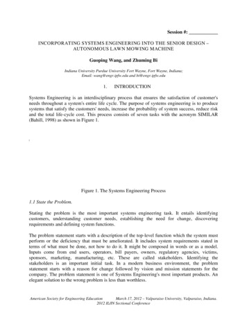
motors, driving wheels assembly, batteries and bumper system implementation and installation,proximity sensor installation, microcontroller wire connections, shaft encoder and limit switchesinstallation, installation of digital compass and emergency stop button, software writing. Apicture of the finished prototype is shown in Figure 4 and Figure 5 describes the flowchart ofsoftware design.Figure 4. Lawn Mowing Machine Picture ShotAmerican Society for Engineering EducationMarch 17, 2012 – Valparaiso University, Valparaiso, Indiana.2012 IL/IN Sectional Conference
STARTInitialize Ports and Variablesint direction 0;Int total sdist 0;Start the wheelchairmotorsIncrement direction by1(direction ;)Read CompassIf Heading erroris greater thanthreshold errorvalueNoRead Proximity sensorYesNoIf Obstacle detectedTurn slight left or rightdepending on the directionand magnitude of errorYesRead Distance fromthe Shaft EncoderStopNoIf Distance Width of lawnPoll limit switchYesNoStop the motors.Reset the BoundaryDistance.Iftotal sdist length oflawnIf bumper switch pressedNoYesLAWN MOWED!StopYesIf direction isan evennumberNoYesTurn Right by 180 Turn Left by 180 Figure 5. Flowchart of Software Design9. TESTING/EVALUATIONThis is the A-stage in “SIMILAR”. During this process, student measure parameters to makesure the designs meet design requirements. The following parameters are measured whichinclude electrical and mechanical ones.Electrical Parameters:Requirement: The mower must be able to make 180 degree turns.Parameter measured: Turn Angle-Requirement: The mower must be able to travel in a straight path usingcompass.Parameter measured: Lateral displacementAmerican Society for Engineering EducationMarch 17, 2012 – Valparaiso University, Valparaiso, Indiana.2012 IL/IN Sectional Conference
-Requirement: The shaft encoder must be used to determine the distance travelledto determine the boundary.Parameter measured: Distance travelled-Requirement: The mower must use the proximity sensor to detect obstacles andstop to avoid collision.Parameter measured: Distance at which it detects obstacles and stopsMechanical Parameters:Motor stall torque: The motor stall torque could not be determined by themanufacturer of the motors. This specification had to be measured.-Bumper system spring stiffness: The bumpers once depressed were returned tothe normal operating position by springs. These springs were purchased from alocal hardware store so their spring constant was not known. The spring constantwas determined by deflecting the spring a measured distance and using a scaledetermined the force required to deflect the spring that distance. This was doneseveral times with different deflection distances and averaged. The springconstant was determined to be 7 lbs./in.-Mower weight: The mower’s total weight was difficult to directly measure, dueto its size and no scale large enough to hold the entire mower at one time.Therefore, each wheel’s reaction force was measure and then summed. Thereaction force was measured using a bathroom scale at each wheel, while usingbooks at the other wheels’ locations to keep the mower level. The total weightwas 160 lbs.Besides running these tests through programmed software and implemented hardware, studentsalso perform mechanical analysis such as drive motor analysis, bumper system analysis, motorkey analysis, drive plate Finite Element analysis, etc. and make sure they meet the desiredobjects.10. RE-EVALUATIONThe evaluations have been integrated through the whole process of SD experience through SDR,PDR, and CDR. Students, faculty members, industrial sponsors provide response/suggestions tothe whole process.11. SUMMARYThe integration of System engineering approach in the SD projects has provided students anexcellent opportunity to the recognition of the methodologies and strategies of systemAmerican Society for Engineering EducationMarch 17, 2012 – Valparaiso University, Valparaiso, Indiana.2012 IL/IN Sectional Conference
engineering approach in their major fields. This approach can prepare students better in theirfuture career after graduation.REFERENCESBahill, A.T. and Gissing, B.(1998), Re-evaluating systems engineering concepts using systemsthinking, In: IEEE Transactions on Systems, Man and Cybernetics, Part C: Applications andReviews, Volume 28, Number 4, pp. 516-527, November 1998.ION Robotic Lawn Mower Competition, WWW: http://www.ion.org/satdiv/alc/American Society for Engineering EducationMarch 17, 2012 – Valparaiso University, Valparaiso, Indiana.2012 IL/IN Sectional Conference
Indiana University Purdue University Fort Wayne, Fort Wayne, Indiana; Email: wang@engr.ipfw.edu and bi@engr.ipfw.edu . 1. INTRODUCTION . Systems Engineering is an interdisciplinary process that ensures the satisfaction of customer's needs throughout a system's entire life cycle. The purpose of systems engineering is to produce