Transcription
2012 Proceedings IEEE INFOCOMSAP: Smart Access Point with Seamless LoadBalancing Multiple InterfacesXi Chen, Yue Zhao, Brian Peck and Daji QiaoIowa State University, Ames, IA 50011{leon6827, yuezh, bpeck, daji}@iastate.eduAbstract—Providing adequate Wi-Fi services to meet user demand in densely populated environments has been a fundamentalchallenge for Wi-Fi networks. In this paper, we explore theemerging OAMI (One-AP-Multiple-Interface) architecture andpropose a unique solution called SAP (Smart Access Point). SAPtakes full advantage of the OAMI architecture to provide seamlesshandoff experience to users, while smartly balancing the networkload across multiple interfaces based on users’ time-varying traffic load conditions. Moreover, we define a Traffic Fulfillment (TF)performance metric to quantify the user experience and aid inassociation scheduling. SAP is an AP-only solution that requirestrivial network modifications and is backwards compatible withlegacy 802.11 stations. We have implemented SAP in the MadWifidevice driver and demonstrated its effectiveness via experiments.I. I NTRODUCTIONWi-Fi hotspot is one of the leading ways for individuals toconnect to the Internet. Clients may use a variety of devices,including smart phones, laptops, tablets, etc., to connect tothe Internet via Wi-Fi hotspots from a variety of commerciallocations, including airports, hotels, retail locations, and coffeeshops. As the popularity of Wi-Fi increases, the demand forbandwidth at each access point also increases. For instance, aWi-Fi network in an airport may need to serve hundreds ofusers and thus a single AP would be insufficient to satisfy thenetwork demand. One possible solution is to deploy multipleAPs throughout the airport terminals so that each AP servesa fewer number of users. However, this solution may havethe following issues. Firstly, in order to maximize the systemperformance, frequent user handoff between APs may beneeded, which is a time-consuming process as a user stationmust disassociate from its current AP and then authenticateand reassociate with a new AP. Secondly, the APs may need toexchange information regarding the connected users to aid inassociation scheduling, which adds a communication overheadto the system. Finally, such a system may have issues routingdownlink traffic to stations which perform a reassociation,causing packets to be delayed or lost.An alternative solution is to equip each AP with multipleWi-Fi interfaces operating on different channels. Such an AParchitecture is called OAMI (One-AP-Multiple-Interface). Inthis paper, we propose a unique SAP (Smart Access Point)architecture based on OAMI, which migrates seamless theconnected stations between multiple interfaces to balance thenetwork load. Specifically, SAP has the following features: SAP introduces an Interface Unification Layer to unifythe appearances of multiple interfaces, which makesseamless handoff a possibility. SAP utilizes a Shared Node Table to facilitate fast reassociation between interfaces. Reassociation can be per-978-1-4673-0775-8/12/ 31.00 2012 IEEEformed simply by copying the station context to anotherinterface and alerting the station of a BSS channel switch. SAP mitigates issues with downlink traffic via a BridgeForwarding Module which allows packets to be forwardedto the correct interface and their final destination. SAP has a Monitoring & Execution Module which monitors various statistics for each connected station (including the traffic rate) and reports them to a CoordinationModule to determine association scheduling. SAP is an AP-only solution without the need of anymodifications at the stations or external routers.The rest of the paper is organized as follows. Observationsmotivating SAP are described in Section II, along with accompanying design goals. The design of the SAP architectureis detailed in Section III. Section IV introduces a networkmodel to calculate the maximum service rate of a station. Wepresent experimental based performance evaluation results inSection V. Related work is discussed in Section VI and weconclude the paper in Section VII.II. M OTIVATIONS AND D ESIGN G OALSIn this section, we discuss the emerging One-AP-MultipleInterface architecture for Wi-Fi networks and present a fewinteresting observations from experiments regarding the stationbehaviors in Wi-Fi networks, which motivate us to design andimplement the proposed SAP architecture. Experiments areconducted with Dell Optiplex desktop and Latitude laptopsequipped with wireless adapters which embed Atheros 5212chipset. Each machine is loaded with a MadWifi devicedriver [1] to collect the experimental data.A. Motivations and Observations1) One-AP-Multiple-Interface Architecture: As Wi-Fi becomes more ubiquitous, in order to serve more Wi-Fi stationsin a network, it is a more cost-effective solution to equip an APwith multiple interfaces operating on different channels thanto deploy multiple APs in the network. However, by simplyadding more interfaces to an AP without carefully planninghow the interfaces shall work together to serve the stations,the OAMI (One-AP-Multiple-Interface) architecture is merely“multiple APs in the same box,” which is shown in Fig. 3(a).Innovations are needed to coordinate between multipleinterfaces so stations can truly enjoy the benefits that OAMIoffers over the conventional OAOI (One-AP-One-Interface)architecture. For example, as multiple interfaces reside on thesame machine under OAMI, the handoff delay of moving astation from one interface to another under OAOI (which willbe discussed next) could be minimized. In another example,1458
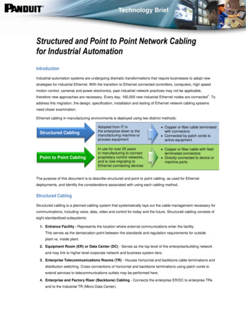
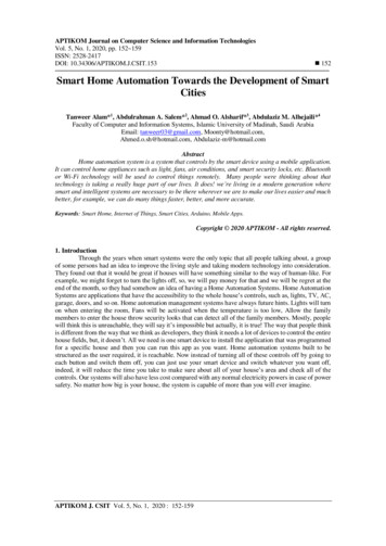
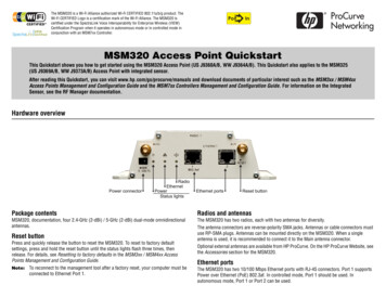
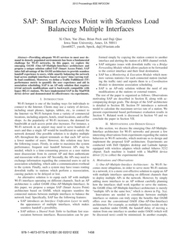
30Throughput (Mbps)the coordination between interfaces under OAMI could beaccomplished internally without introducing extra communication overhead to the backbone network (such as Ethernet)that connects the interfaces (on different APs) under OAOI.2) Long Handoff Delay under OAOI: The IEEE 802.11handoff process (to move a station from an AP to another)could be very time-consuming [2], [3]. During the process,the station needs to perform channel scanning, authenticationand reassociation. Moreover, additional procedures that maybe needed at higher layers such as DHCP discovery couldrender the entire process even longer.We examine how large the handoff delay could be with asimple experiment that uses two APs and one station. Thestation keeps sending Ping packets to a remote server, onceevery 200 ms. At the 8-second mark, the station starts thehandoff process to associate with the other AP. Fig. 1 plotsthe RTT (Round Trip Time) of the Ping packets. As shown inthe figure, the entire handoff process takes about six seconds tocomplete, during which the station experiences severe servicedisruption; this is evidenced by the drastically increased RTTsof Ping packets during the process.Low rate STAHigh rate STA2010005001000Traffic Rate (Kbps)2000Fig. 2. Throughput comparison when the low-rate (1 Mbps) station is underdifferent loads. Two stations are used in the experiment and the high-rate(54 Mbps) station is always saturated.as the low-rate station only contends for the channel sporadically. As the load of the low-rate station increases, theperformance anomaly becomes more apparent. When the lowrate station becomes saturated with a load of 1000 or morepackets per second, the classic performance anomaly appearswith two stations receiving an equal throughput and the overallsystem throughput suffering a significant drop.In practice, as stations could be very diverse in terms oftheir traffic loads, it is important to consider the actual loadcondition of each station (whenever possible) when makingthe association scheduling decisions.RTT (ms)1005000Fig. 1.2468Time (sec)10121416Large RTT of the Ping packets during the legacy handoff process.In practice, it is always desirable to have a seamless handoffprocess with minimal handoff delay and thus eliminate theservice disruption, which could be critical to many userapplications such as real-time video streaming.3) Revisit of Performance Anomaly: Performance anomalyis a well-known phenomenon in 802.11 networks [4]. It iscaused by the transmission rate diversity between all stationsassociated with the same AP. With rate diversity, the high-ratestation is “slowed down” by the low-rate station because the802.11 protocol is designed to allow all contending stations toaccess the channel with an equal probability. Due to throughput loss of performance anomaly, many association schedulingschemes try to avoid it by considering the transmission rateswhen making association decisions. For example, stations maybe grouped according to their transmission rates; all the highrate stations are associated with one AP while another APserves all the low-rate stations.One of the key assumptions in the performance anomalystudy is that all contending stations are saturated or heavilyloaded. We now revisit the performance anomaly in practicalscenarios where the low-rate station may be under variousloads. In the experiment, we associate two stations with thesame AP; one of them communicates with the AP at the low1 Mbps rate while the other at the high 54 Mbps rate. The highrate station is always saturated while the load of the low-ratestation increases gradually from 10 Kbps to 2000 Kbps.As shown in Fig. 2, when the low-rate station is lightlyloaded, the throughput of the high-rate station is less affectedB. Design GoalsBased on the above observations, we propose in this worka SAP (Smart Access Point) realization of the OAMI architecture. With SAP, the AP shall be able to: adjust the association scheduling decisions between multiple interfaces dynamically based on stations’ actual andvarying traffic load conditions; and execute the association scheduling decisions with seamless handoff of stations between interfaces with minimalhandoff delay, by taking full advantage of the OAMIarchitecture.Moreover, SAP shall be an AP-only solution. It shall notrequire any modification at the client side and shall work withall legacy stations, thus facilitating its practical deployment.III. T HE P ROPOSED SAP A RCHITECTUREIn this section, we first present an overview of the proposedSAP architecture, then describe each SAP module in detail.A. SAP OverviewThe overall structure of the proposed SAP architectureis shown in Fig. 3(b). In comparison to the basic OAMIarchitecture in Fig. 3(a), SAP has the following additionalfunction blocks: (i) Interface Unification Layer; (ii) SharedNode Table; (iii) Bridge Forwarding Module; (iv) Monitoring& Execution Module; and (v) Coordination Module. All thesemodules are implemented at the AP only, without the need ofany modifications at the stations or external routers.(i) Interface Unification Layer. SAP creates an InterfaceUnification Layer to unify the appearances of multipleinterfaces, which makes the handoff process transparentto the stations and thus seamless handoff a possibility.Details will be discussed in Section III-B1.(ii) Shared Node Table. Different from OAMI, where eachinterface maintains a separate table of the stations thatare associated with it, SAP allows multiple interfaces to1459
discussed above. It accepts the statistics reported by theMonitoring & Execution Modules of multiple interfaces,and runs an association scheduling algorithm periodicallyto determine which station should be moved to anotherinterface. Based on the output of the algorithm, it issuescommands to the Monitoring & Execution Module, andupdates the Bridge Forwarding Table accordingly. Detailswill be discussed in Section III-B5. (a) The basic OAMI architecture.-(( . # ( /(.0!/# # 123 3 456768 9( #)& # ( : ;.# . 9( # . # ! :% 9( ?# () # ( )& .0! #! ( &?; (. )#!!@: !! *ABC & D &EF' G . D EF' 9#) I D# &EF/( ( KCL )0 ( /(.0!' 9#) J D# &IFH&# ./( ( K*(.CL )0 ( /(.0!B# !' 9#) 9 )# ( 4#@HBA I"# # %# &HBA J'() !HBA M* ! ,(b) Our proposed SAP architecture.Fig. 3. Comparison of our proposed SAP architecture and the basic OAMIarchitecture. Function blocks added in SAP are marked in bold.share a single node table. This simplifies significantly thecontext transfer procedure that is required by the handoffprocess. Details of the Shared Node Table structure willbe discussed in Section III-B2.(iii) Bridge Forwarding Module. In OAMI, after handoff, tomake sure proper forwarding of a station’s downlinktraffic through the new interface to reach the station, therouting table at an external router needs to be updated.In comparison, SAP sets up an internal bridge for thispurpose. Details of the Bridge Forwarding Module willbe discussed in Section III-B3.(iv) Monitoring & Execution Module. In SAP, each interfacemonitors the statistics of all the stations that are associated with it, including the physical transmission rates, thetraffic rates, and the data payload sizes. Collected statistics are reported to the Coordination Module that usesthem as inputs to its association scheduling algorithm.Meanwhile, the Monitoring & Execution Module alsoaccepts commands from the Coordination Module andexecutes them by sending the corresponding managementframes to the station if needed. Details of this module willbe discussed in Section III-B4.(v) Coordination Module. The Coordination Module in theuser space coordinates the behaviors of all modulesB. SAP ModulesThis section describes the five modules of SAP in detail.1) Interface Unification Layer: In the basic OAMI architecture, different interfaces (i) have different MAC addresses,(ii) operate on different non-overlapping channels, and (iii)may have different BSSIDs. Therefore, in order for a stationto continue receiving services from the AP via a differentinterface than the current one it is associated with, it needsto not only switch to the channel that the new interfaceoperates on, but also use the BSSID and MAC address ofthe new interface when preparing its packets; otherwise, allits packets will simply be discarded by the new interface dueto mismatch of information. For this reason, the conventionalhandoff process typically consists of the following steps [5]:(i) The station performs channel scanning;(ii) The station extracts the BSSID and MAC address of thenew interface from Beacon/Probe Response frames;(iii) The station switches to the channel that the new interfaceoperates on;(iv) The station exchanges management frames with the newinterface to complete authentication and reassociation;(v) The station prepares its packets using the BSSID andMAC address of the new interface and starts communicating with the AP via the new interface.As we can see, the station is required to participate activelyin the entire handoff process, where various delays occur atvarious steps of the process.To simplify the handoff process and reduce the handoffdelay, SAP introduces an Interface Unification Layer (IUL).It unifies all interfaces and makes them appear the same(except that they operate on different non-overlapping channels) to the stations by setting the same BSSID and thesame MAC address for all interfaces. This could be done via,for example, the ioctl command (to set the BSSID) andthe ath attach() function (to set the MAC address) inMadWifi. As a result, Step (v) of the handoff process couldbe avoided completely. As we will discuss next, with thehelp from the Shared Node Table structure and the BridgeForwarding Module, which help remove Step (iv), and theMonitoring & Execution Module together, which help removeSteps (i) and (ii), the handoff process is simplified to achannel switch operation, thus reducing the handoff delay tothe minimum.2) Shared Node Table: As we mentioned in Section III-B1,in the basic OAMI architecture, a station has to performauthentication and reassociation before being served again bythe new interface. The root reason for this requirement isthat, under OAMI, each interface maintains a separate nodetable that keeps track of only the stations that are associatedwith it, as shown in Fig. 4(a). Therefore, the context transfer1460
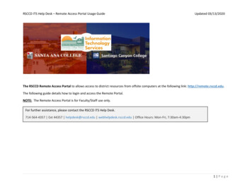
procedure during the handoff process under OAMI consists ofthe following steps: Firstly, the station disassociates from the current interfacewhich then removes the corresponding entry from its nodetable; Then, the station scans, authenticates (e.g., key exchanges) and reassociates with the new interface; Finally, the new interface creates a new entry in its nodetable, which is populated by the context informationof the station, such as security information, associationinformation, and so on.As we can see, the station has to go through the timeconsuming authentication and reassociation in order to createan entry in the new interface’s node table.NOPQRSTUQ V WTPXYZ] Q PT aQbOVO[O\NOPQRSTUQ c WTPXVZ] Q PT aQbOcOd(a) Default node table structure.efghijklh m nkgopqfmtokihu fvuh gkwxhyfm fr fsfz f{ne mq ne rq ne rq ne mq ne mqfry }vuh x f x g f goh fvuh gkwxhefghijklh r nkgomq f jklh gokg goh fvuh ne mqy l ohiihfgghix k vl kghu go(b) Shared node table structure in SAPFig. 4. Comparison of the shared node table structure in SAP and the defaultnode table structure.The context transfer procedure described above does nottake advantage of the fact that the interfaces reside on thesame machine under OAMI, which means that they are servedby the same kernel and the same memory space. Hence,it is possible to simplify the context transfer procedure viainternal actions, which is exactly what SAP does. Specifically,SAP maintains a single node table shared by all interfaces,as shown in Fig. 4(b). Each entry in the shared node tablenow has an extra flag to indicate the interface that the stationis currently associated with. With such a shared node tablestructure, the context transfer procedure is simplified to asimple modification of a flag in the shared node table. As aresult, authentication and reassociation are avoided completely.3) Bridge Forwarding Module: In the basic OAMI architecture, upon a successful handoff of a station to a new interface,the external router needs to update its routing table so thedownlink packets for the station could be routed properlytoward the new interface. SAP uses a different forwardingmechanism to achieve this purpose. It is an internal approachthat limits all the modifications within the AP only.Specifically, SAP establishes an internal bridge that interconnects the multiple interfaces at the data link layer, and eachinterface is assigned a bridge port number. The bridge has aforwarding table which contains entries for each station thatis associated with the AP. Each entry contains the followinginformation: (i) the MAC address of the station; and (ii)the bridge port number of the interface that the station isassociated with. As shown in Fig. 3(b), all the downlinkpackets are first routed to the bridge, and then forwarded tothe appropriate interface by looking up the bridge forwardingtable. Upon a successful handoff of a station, SAP updates thecorresponding entry in the bridge forwarding table, in additionto the corresponding entry in the Shared Node Table discussedin Section III-B2.4) Monitoring & Execution Module: In SAP, each interfacemonitors the stations that are associated with it and collectsthe station statistics for facilitating the association schedulingalgorithm in the Coordination Module. The collected statisticsinclude the downlink and uplink traffic rates, the transmissionrate and the data payload length of each station. SAP maintainsa moving average for each statistic, and updates it upon eachpacket transmission/reception.Based on the collected statistics, each interface reports thefollowing information to the Coordination Module periodically: λ, r and Ldata . Here, λ is the overall traffic rate of thestation, and we use the uplink throughput to approximate theuplink
SAP: Smart Access Point with Seamless Load Balancing Multiple Interfaces Xi Chen, Yue Zhao, Brian Peck and Daji Qiao Iowa State University, Ames, IA 50011 {leon6827, yuezh, bpeck, daji}@iastate.edu Abstract—Providing adequate Wi-Fi services to meet user de-mand in densely populated environments has been a fundamental challenge for Wi-Fi networks.