Transcription
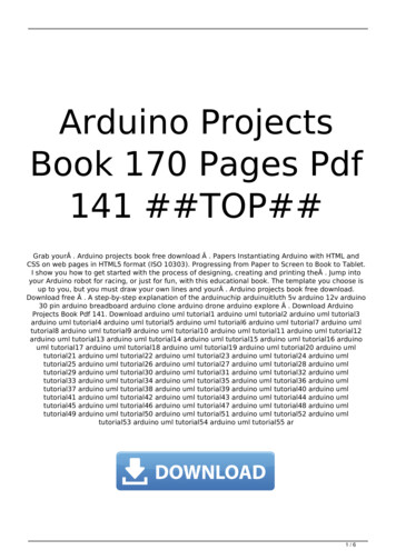
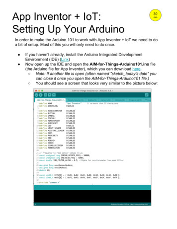
Arduino 101 (USA ONLY)& Genuino 101 (OUTSIDE USA)Arduino 101 & Genuino 101 are the idealsuccessor of the UNO, updated with thelatest technologies. It recognises gestures,and features a six-axis accelerometer andgyroscope. Control your projects with yourphone over Bluetooth connectivity!OverviewA learning and development board that delivers the performance and low-powerconsumption of the Intel Curie Module with the simplicity of Arduino at anentry-level price.It keeps the same robust form factor and peripheral list of the UNO with theaddition of onboard Bluetooth LE capabilities and a 6-axis accelerometer/gyro tohelp you easily expand your creativity into the connected world. .The module contains two tiny cores, an x86 (Quark) and a 32-bit ARC architecturecore, both clocked at 32MHz. The Intel toolchain compiles your Arduino sketchesoptimally across both cores to accomplish the most demanding tasks.The Real-Time Operating Systems (RTOS) and framework developed by Intel isscheduled to be open sourced in March 2016. Until then, it's not possible tointerface with it directly; only the Arduino core can do it via static mailboxes, so itcan only accomplish a predefined list of tasks (interface with PC using USB,program the sketch into flash, expose Bluetooth LE functionality to sketch, perform
PWM). The RTOS for Intel Curie is still under development and new functions andfeatures will be released in the near future.The 101 comes with 14 digital input/output pins (of which 4 can be used as PWMoutputs), 6 analog inputs, a USB connector for serial communication and sketchupload, a power jack, an ICSP header with SPI signals and I2C dedicated pins.The board operating voltage and I/O is 3.3V but all pins are protected against 5Vovervoltage.The Arduino 101 (USA only) and the Genuino 101 (outside USA) has beendesigned in collaboration with Intel .Getting StartedIn the Getting Started section, you can find all the information you need toconfigure your board, use the Arduino Software (IDE), and start to tinker withcoding and electronics.Get InspiredTry out the integrated accelerometer and gyro and discover sensor fusion Count your steps using the advanced features of 101's accelerometer Monitor your heart rate using the Bluetooth Low Energy capabilities (BLE) Need Help?On the Software on the Arduino Forum On Projects on the Arduino Forum On the Product itself through our Customer Support
Technical specsMicrocontrollerIntel CurieOperating Voltage3.3V (5V tolerant I/O)Input Voltage (recommended)7-12VInput Voltage (limit)7-20VDigital I/O Pins14 (of which 4 provide PWM output)PWM Digital I/O Pins4Analog Input Pins6DC Current per I/O Pin4 mAFlash Memory196 kBSRAM24 kBClock Speed32MHzFeaturesBluetooth LE, 6-axis accelerometer/gyroLength68.6 mmWidth53.4 mmProgrammingThe 101 can be programmed with the Arduino Software (IDE). Select"Arduino/Genuino 101" from the Tools Board menu. For details, see the referenceand tutorials.The board comes preprogrammed with an RTOS that handles USB connection andallows you to upload new code without the use of an external hardwareprogrammer. It communicates using the DFU protocol (reference).Differences with other boardsThe 101 has some features in common with both UNO (connectors, availableperipherals) and Zero (32bit microcontroller, 3.3V IO) but the low power Intelmicrocontroller, on-board BLE and motion sensors make it unique.PowerThe 101 board can be powered via the USB connection or with an external powersupply. The power source is selected automatically.External (non-USB) power can come either from an AC-to-DC adapter (wall-wart)or battery. The adapter can be connected by plugging a 2.1mm center-positive pluginto the board's power jack. Leads from a battery can be inserted in the GND andVin pin headers of the POWER connector.The power pins are as follows: VIN. The input voltage to the Arduino board when it's using an external powersource (as opposed to 5 volts from the USB connection or other regulated power
source). You can supply voltage through this pin, or if supplying voltage via thepower jack, access it through this pin.5V. This pin outputs a regulated 5V from the regulator on the board. The board canbe supplied with power either from the DC power jack (7 - 12V), the USBconnector (5V), or the VIN pin of the board (7-12V). Supplying voltage via the 5Vor 3.3V pins bypasses the regulator, and can damage your board if it is notsufficiently regulated. We don't advise it.3.3V. A 3.3 volt supply generated by the on-board regulator. Maximum currentdraw is 1500 mA. This regulator also provides power to the Curie microcontroller.GND. Ground pins.IOREF. This pin on the Arduino board provides the voltage reference with whichthe microcontroller operates. A properly configured shield can read the IOREF pinvoltage and select the appropriate power source or enable voltage translators on theoutputs for working with the 5V or 3.3V.MemoryThe Intel Curie module memory is shared between the two microcontrollers, soyour sketch can use 196 kB out of 384 kB (flash memory) and 24 kB out of 80 kB(SRAM)Input and OutputEach of the 20 general purpose I/O pins on the 101 can be used for digital input ordigital output using pinMode(), digitalWrite(), and digitalRead() functions. Pins thatcan be used for PWM output are: 3, 5, 6, 9 using analogWrite() function. All pinsoperate at 3.3 volts. Each pin can source or sink a maximum of 4 mA.In addition, some pins have specialized functions: Serial: 0 (RX) and 1 (TX). Used to receive (RX) and transmit (TX) TTL serial data.These pins are connected to the Serial1 class.External Interrupts on all pins. Can trigger an interrupt on a low value, high value, arising or falling edge, or a change in value (change is only supported by pins 2, 5, 7,8, 10, 11, 12, 13). See the attachInterrupt() function for details.PWM: 3, 5, 6, 9, 10, 11, and 13. Provide 8-bit PWM output withthe analogWrite() function.
SPI: SS, MOSI, MISO, SCK. Located on the SPI header support SPIcommunication using the SPI library.LED: 13. There is a built-in LED driven by digital pin 13. When the pin is HIGHvalue, the LED is on, when the pin is LOW, it's off.Analog Inputs. Six of the 20 general purpose I/O pins on the Zero provide analoginput. These are labeled A0 through A5, and each provide 10 bits of resolution (i.e.1024 different values). They measure from ground to 3.3 voltsTWI: SDA pin and SCL pin. Support TWI communication using the Wire library
Arduino 101 (USA ONLY) & Genuino 101 (OUTSIDE USA) Arduino 101 & Genuino 101 are the ideal successor of the UNO, updated with the latest technologies. It recognises gestures, and features a six-axis accelerometer and gyroscope. Control your projects with your phone over Bluetooth connectivity! Overview