Transcription
ICEM Mesh for CFD Analysis
Index1.2.3.4.5.6.7.8.2Introduction to ICEMGeometry HandlingShell MeshingVolume MeshingPrism MeshingMesh Preparation Before Output to SolverOutput to SolverICEM CFD Hexa
1. Introduction to ICEM3
What is a Mesh? 4Mesh– Volume comprised of elements used to discretize a domain for numerical solution Structural Fluid dynamics Electromagnetics Other– Elements 0D – Node element– Point mass– Constraint, load location 1D – Lines– Bars, beams, rods, springs– 2D mesh boundary 2D – Surface/Shell– Quads– Tris– Thin sheet modeling– 2D volume– 3D mesh boundary 3D - Volume– Tetra– Pyramid– Penta (prism)– Hexa– Solid modeling– 3D fluid modeling Formats– Unstructured– Block Structured– Nodes Point locations of element corners
Ansys ICEM CFD Features Geometry Creation/Repair/Simplification– Including Mid-Plane Extractions/Extensions– Most geometry intended to be imported Powerful Meshing tools– Tetra/Prism from CAD and/or existing surfacemesh– Shell meshing: structured, unstructured– Hex-dominant, swept, Structured hexa, Extrudedquads, Body-fitted and stair-step Cartesian– Hybrid meshing (merging, multi-zone) 5Advanced mesh editingSolver SetupOutput to 100 SolversScripting and much more
GUI and LayoutUtility MenuUtilityIconsFunction TabsSelection ToolbarModelTreeDisplay TriadData EntryPanel6MessageWindowHistogramWindow
File and Directory Structure Use of many files All files can optionally be associated within a Project Primary file types:– Not one large common database– For faster input/output– Establishes working directory– Settings (*.prj) file contains associated file names– Tetin (.tin): Geometry Geometry entities and material pointsPart associationsGlobal and entity mesh sizesCreated in Ansys ICEM CFD or CAD Interface.prj– Domain file (.uns) Unstructured mesh.tin– Blocking file (.blk).blk Blocking topology.uns– Attribute file (.fbc, .atr) Boundary conditions, local parameters & element types– Parameter file (.par) solver parameters & element types.fbc– Journal and replay file(.jrf, .rpl) Record of performed operations (echo file)7.rpl.par.jrf
Mouse Usage ‘Dynamic’ viewing mode (click and drag)– left:rotate (about a point)– middle:translate– right:zoom (up-down)screen Z-axis rotation (sideways)– WheelzoomSelection mode (click)– left:select (click and drag for box select)– middle:apply operation– right:unselect last selection 8F9 toggles the mouse control to Dynamic mode while in Selectmode– Toggle Dynamics button also–does thisSpaceball allows for dynamic motion even while in select mode
Utility MenusFile Menu(file i/o)9Edit MenuView MenuInfo MenuSettingsMenu(preferences)Help Menu
File menu To open/save/close– Projects Will open/save/close all associated files including Geometry (*.tin) Mesh (*.uns) Attributes (*.fbc, *.atr)– All file types can be opened/saved/closed independentlyAlso to– Import/Export Geometry/Mesh– Invoke scriptingExitSave frequently!10 Several common functionsare duplicated as utilityicons:Open ave ProjectOpen/Save/CloseBlocking
Other Commonly Used Utilities Edit Undo/RedoAlso here View– Fit Fit visible entities into screen– Box Zoom– Standard views Top, Bottom, Left, etc. Can also select X, Y, Z axis of display triad in lo wer right hand corner of main view screen to orient to standard views, e.g. selecting “X” will orient “right”Isometric – select blue dot within triadMeasure– Distance– Angle– Location11– Local Coordinate System Used by:Select locationMeasuringNode/point movement/creationAlignmentLoadsTransformation– Surface display Wireframe Solid Transparent
Help Bubble explanation with cursorpositioning12Menu Driven– Searchable– Includes tutorials– Programmers guide (for ICEMCFD/Tcl scripting procedures)Hyper-link to specific topic
Common Function TabsGeometryMeshBlockingCreate/Modify geometrySet mesh sizes, types and methodsSet global mesh optionsAuto create Shell, Volume, Prism meshesInitialize blockingSplit/modify blocksGenerate structured hexa meshEdit MeshCheck errors/problems, Smooth, Refine/Coarsen,Merge, repair mesh, Transform, etc.Output13Set Boundary Conditions and ParametersWrite mesh for 100 solvers.
Structural Function Tabs Only available when solver is set to Abaqus, Ansys, Autodyn, LS-Dyna, or Nastran Settings- Product must also be set to an FEA versionPropertiesCreate, read, write out materialpropertiesApply to geometry/elementsSet constraints,displacements, definecontacts, initial velocity,rigid wallsConstraintsLoadsSolveoptions14Set force, pressure andtemperature loadsSet parameters, attributes,create subcases, write outinput file, run solver
Selection Toolbar During select mode, popup selection toolbar appears– Some tools are common to all, others are contextual– Linked to select mode hotkeys– Filtering of entities and mass-selection methodsSelect By PartGeometryPolygonSelect allCancelFlood fill to AngleOnly visibleEntity FilterFlood fill to CurveMesh attached to GeometryMeshCircleEntire/Partial toggleBlocksToggle DynamicMode (F9)15By SubsetFromCornersSet Flood FillAll ShellsangleToggle between mesh and geometryFacetedGeometrySegmentsIn betweensegments
Model Tree To toggle on/off various sections of the modelMain Categories are:– Geometry, Mesh, Blocking, Parts– Local Coord Systems, Element Properties,Connectors, Displacements, Loads and Material PropertiesToggle check boxes to blank/unblank– Blanked/inactive– Visible/active 16– Partially visible/active: some sub membersturned on, some turned offClick on plus sign to expand tree– Expose sub membersRight mouse click for display options
Model Tree: Parts 17Parts– Grouping of mesh, geometry, and blocking entities Based on boundary condition/property Based on mesh size (can set mesh size by part) Based on material property Just to partition large model– Select to blank/unblank all entities within part– Color coded: Part name matches entity screen display– Right Mouse Button on Parts to access: Create Part Create Assembly Delete Empty Parts Etc.RMB on specific part names allows options to modify or delete the partsProperties are shown as a sub branch of the part– Double Left Click or RMB Modify to modify element properties
WorkflowTypical ICEM CFD Workflow:Create/open new projectImport/Create geometryBuild topology/Clean geometry/Create geometryMesh model (Possibly Hex Blocking)Check/edit meshOutput to SolverGeneral Order of Workflow18
Accessing from Workbench Ansys ICEM CFD 14.0 is not fully linked inside Workbench– Export files from Mechanical Model (Simulation) or Meshing Application to open in ICEM CFD Some ICEM CFD capabilities havebeen integrated into the MeshingApplication– Tetra octree (patch independent)– 3D blocking fill (Multizone)– Autoblock (2D, uniform quad)– Body fitted cartesian19
Workbench Interactive Link Ansys ICEM CFD can be accessed from Workbench from certain mesh methods Insert a meshing method– MultiZone– Patch Independent tetrahedrons Set Write ICEM CFD Files to Interactive Generate mesh Edit or remesh within ICEM CFD,save project, then exit ICEM CFD– Don’t edit geometry in ICEM CFD20
2. Geometry Handling21
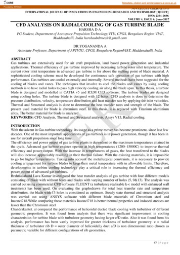
Geometry handlingANSYS ICEM CFD was designed to mainly import geometry, not createcomplicated geometries, although many geometry tools are providedAn accurate solution reflects the underlyinggeometry. To get such, ICEM CFDprovides: Geometry import– From CAD package– 3rd party formats (step, acis, etc )– Via Workbench/ Design Modeler Surface geometry kernel– Imported solids are converted tosurfaces Many internal CAD tools– Geometry creation– Geometry modification– Geometry fixing22This Jet engine model was built solely withICEM CFD geometry tools
Geometry ImportCAD from just about any source Workbench Readers – for most CAD imports– Anything that Workbench can import can also be imported into ICEM CFD using Workbench readers– Requires a Workbench installation! 3rd-party import Parasolid– ACIS (.sat) STEP/IGES GEMS– DWG/DXF Direct CAD Interfaces– Legacy interfaces which are not updated. Use Workbench Readers instead for current CAD versions– Set up ICEMCFD/AI*E meshing requirements within CAD environment Saved within CAD part for parametric geometry changes– Directly write out ICEM formatted geometry (tetin file) No 3rd party exchange (clean!)– ProE, Unigraphics, Solidworks, Catia V4, IDEAS (IDI)– ProE, UG, and Solidworks imports require CAD libraries; CAD software and licensing must be available23
Geometry Import - other sourcesWhen CAD is not available, an old legacy model or x-ray scanof the part can be imported as geometry. This input is a collection of facets (triangulated surfaces). Faceted Data– Nastran– Patran– STL (most common)– VRML– Other solver formats (indirectly from mesh conversion) Formatted Point Data– Auto curve/surface creation from regular table of points24
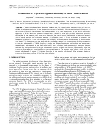
Open Geometry Geometry saved as “tetin” (*.tin file)– Legacy name as an abbreviation of “tetrainput.”– Surface geometry kernel Any imported solid models are represented as aseries of watertight surfaces– Surfaces are internally represented astriangulated data Resolution or approximation of true bsplinesurface data set by Triangulation Tolerance insettings model Smaller value better resolution 0.001 works best for most models Use a high tri tolerance to work with a largemodel, but lower the tolerance when it comestime to compute the mesh Not used if surfaces are already facetized (e.g.STL, VRML)25Tri tolerance 0.1Tri tolerance 0.001
Geometry Creation ToolsFirst 3 icons tocreate geometry 26Screen SelectExplicit CoordinatesBase Point and DeltaCenter of 3 Points/ArcBased on 2 LocationsCurve EndsCurve-Curve IntersectionParameter along a CurveProject Point to CurveProject Point to Surface From PointsArc Through 3 PointsArc from Center Point/2 Pointson PlaneSurface ParameterSurface-Surface IntersectionProject Curve on SurfaceSegment CurveConcatenate CurvesSurface Boundary ExtractionModify CurvesCreate MidlineCreate Section Curves Untrim SurfaceCurtain SurfaceExtend SurfaceGeometrySimplification––From CurvesCurve DrivenSweep SurfaceSurface of RevolutionLoft Surface OverSeveral CurvesOffset SurfaceMidsurfaceSegment/Trim SurfaceMerge/ReapproximateSurface Convex HullCartesianShrinkwrapCreate eDiscTrim normal tocurve
Create Body Material point and body– Material point used by tetra octree to instruct which volumeregions to keep Volume elements will be in the same part as the materialpoint– Used in hexa blocking as a part for placing blocks– Material point method is most robust– By Topology method automatically creates a material point inevery closed volume Requires build diagnostic topology first to determineconnectivity Can save you the work of creating a lot of materialpoints for each region Any regions not completely closed (yellow curvesindicating gaps/holes) will not get a material point sothis is less robust27
Faceted Geometry HandlingCreate/Modify Faceted Convert from BsplineCreate CurveMove nodesMerge nodesCreate segmentDelete segmentSplit segmentRestrict segmentsMove to new curveMove to existingcurve Convert from B-spline Coarsen SurfaceCreate new Surface Merge Edges Split Edges Swap Edges Move NodesMerge Nodes 28Create TrianglesDelete TrianglesSplit Triangles Align Edge to CurveClose Faceted HolesTrim by Screen LoopTrim by Surface LoopRepair SurfaceCreate CurveRestrict TrianglesDelete TrianglesMove to new SurfaceMove to new SurfaceMerge SurfacesFacetted (triangulated)surfaces
Geometry HandlingRepair GeometryTransformation Tools 29Build DiagnosticTopologyCheck GeometryClose HolesRemove HolesStitch/Match EdgesSplit Folded SurfacesAdjust varying ThicknessModify surface normalsBolt hole detectionButton detectionFillet detection TranslateRotateMirrorScaleTranslate & Rotate––Three PointsCurve to CurveRestore DormantEntity Curves/pointsoriginally madeinactive - ignoredby meshing tools Restore to activateagain -seen asconstraints bymeshing tools DeletePointsCurvesSurfacesBodiesAny EntityBuildtopologywithfiltering
Building Topology – Determine Connectivity Geometry - Repair Geometry - Build Diagnostic TopologyTo diagnose potential geometry problems––––Shows potential leakage (tetra octree) before meshingShows where surface mesh may not be connectedPatch dependent surface mesher requires build topologyTolerance Specifies allowable gap between surfaces Size should be set reasonably to ignore small gaps, but not ignore leakage (tetra octree) or remove important features Default is 1/2500th of the diagonal of the bounding box Connectivity is set up between surface edges that meet within the tolerance Filtering should be off when using to determine connectivityEdge 1Edge 2Tolerance30
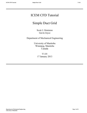
Building Topology – Color CodingColor coding Topology curves are color coded to indicate their surface connection status– green unconnected, yellow single, red double, blue multiple, Grey dormant (filtered out)– Turn color coding off/on in Model tree Geometry Curves Color by count– Red curves indicate two surfaces meet within the tolerance, This is what you want for a solid model.– Yellow curves will usually indicate some repair is requiredCan you spot thehole in the solid?Build Topology31Yellow curvesNow you can find the indicate that thesurface is probablyholemissing or the gap isgreater than thetoleranceRed curves indicate thatsurfaces meet withinthe tolerance setting
Build Topology – Extract Curves and Points Automatically extracts curves and points from thesurfaces– Filter by angle (default 30 degrees) Filter Points: Points between two curves whose tangency is below the feature angle will be “filtered out” (made dormant) Filter Curves: Curves between two surfaces whose tangency is below the feature angle will be “filtered out” (made dormant)NofilteringFilteringTetra octree and patchdependent surfacemesher enforce nodes onthe curvesNeeds smallermesh size atfillets32
Build Topology – Segment Surfaces Automatically segments all surfaces where curveseither make a complete loop on the surface or spanacross the surface Turn Split surface at T-connections off to turn offsegmentingYou can then delete anysurfaces you don’t wantBuildtopologyCheck off to disablesegmenting33
Tolerance setting Set adequate tolerance!– Example: some multiple (blue) edges. This indicates that more then two surfaces meet within the tolerance setting– Turning on the surfaces reveals one surface is now missing.– In this case, the tolerance (0.2) was set to greater than the thickness (0.1). One of the surfaces was seen as a “duplicate” within the tolerance and removed. UNDO– You will need to exercise care not to damage your model with build topology Too small is safer but indicates more gaps Too big can alter the model in bad ways– Rule of thumb: tolerance should be about 1/10th smallest foreseen mesh size or smallest feature that you wish to capture– Build topology will delete duplicate geometry because its tolerance iszero340.1
Building Topology – Other Options– New Part Name Inherit Part: Default: new curves and points will inherit the part names from surfaces they are extracted from– Check off Inherit Part to type a new name or choose from the list– Single curve cleanup Merges single edge curves with a second tolerance while resolving sliver surfaces (normally larger than base tolerance)– Split Surface at T-connections Resulting mesh will conform to common edge even though the surface is not split into two separate surfaces Will also split a surface into separate surfaces ifthe curves form a closed loop or span across the surface– Split Surface at Interior Curves Surfaces trimmed along curves that don’t span surface or form a closed loop Resulting mesh will conform to curve35
Building Topology – Other Options– Method All parts, default method Only visible parts– Build topology is only run on active Parts in the model tree– Inactive Parts are not affected Selection– Build topology on one or more surface entities– Part by part Build topology is run on one part at a time Use with assemblies to keep parts separate Otherwise build topology may fix gaps, create T-connections or remove duplicates across Parts– Delete unattached curves and points Removes unattached curves (green) and points after running build topology Easy clean-up of unwanted curves/points Users may, however, wish to keep these curves/points for construction purposes (turn option off)36
3. Shell Meshing37
Introduction to Shell Meshing Usages of shell meshing:–Thin sheet solid modeling (FEA) – stamped parts–2D cross sectional analysis (CFD)–Input for volume meshing (FEA/CFD) – Delaunay, Advancing Front, T-grid– Filling a surface mesh is faster than tetra octree but requires well-connected geometry Procedure– First need to decide mesh setup parameters Mesh method– Algorithm used to create mesh Mesh type– quad/tri/mix38 Mesh sizes– Small enough to capture physics, important features– Large enough to reduce grid size (number of elements)» Memory limitations» Faster mesh/solver run– Set mesh sizes on parts, surfaces, and/or curves– Based on edge length– Can have different types/methods set on different surfaces
Global Mesh Setup Mesh Setup IconsGlobal Mesh Setup– To change defaults globallyfor size, method and type– For entire model– For Shells– For Volume– For Prism– To set periodicity Mesh tab Global Mesh Size–For entire model–Scale factor Global setting by which many local settings aremultiplied Good for scaling overall mesh– Parameters relative toscale factor– Max size– Min size limit– Max deviation39Global Element Seed Size Maximum possible element size in model Default size if don’t wish to set local sizes–Curvature/Proximity Based Refinement Automatically creates smaller element size tobetter capture geometry Only for Patch Independent method and tetraoctree
Global Shell Meshing Parameters 40Shell Mesh Setup– From Global Mesh Setup tab– Set surface mesh parameters globally Defaults for the selected mesh method– Methods Autoblock Patch dependent Patch independent Shrinkwrap Delaunay– Type All Tri, Quad w/one tri, Quad dominant, All quad– Options for different methods– Global types and methods can be overridden by Surface Mesh Setup– Local settings Compute Mesh
41Part Mesh SetupPart Mesh Setup (pop up spread sheet)– Set mesh parameters on all entities within part– Max. size Multiplied by global Scale Factor actual sizeQuad layers grown from curves (e.g. rings around holes), use these 3parameters:– Height: First layer quad height on curves– Height ratio: growth ratio which determines the heights of eachsubsequent layer– Num layers: Number of rings/inflation layersFor quad layers, the minimum required to be set is height (for 1 layer) ornumlayers (height max. size)Or set onIf done in the Part Mesh Setup spreadsheet you must toggle on Applyindividualinflation parameters to curvescurves
Local Surface Mesh Setup 42Surface Mesh Setup– Same parameters as part mesh setup but alsoincludes: Mesh type Mesh method– Select surfaces first from screen, setsizes/parameters and Apply– Mesh method/type will override global shellmesh settings for selected surface(s)– Will override Part Mesh Setup settings if setafterward– Display Right mouse, select in Model tree onSurfaces Tetra/Hexa Sizes– 1 Icon appears for each surface– Gives you a visual estimate ofprescribed max. size
Local Curve Mesh Setup – General Curve Mesh Setup– General Same as Surface Mesh Setup But also can prescribe Number of nodes– Instead of element size Also includes node biasing along curves– Initial spacing from either curve end– Bunching lawsSide 1 – Expansion ratios from either curveend– Matching of node spacing toadjacent curves– For a better description, refer to theSide 2Hexa chapter – Edge ParametersArrow Select curves first, middle mouse toshows sideaccept selection, then type in parameters/1 and sidesizes - ApplyDisplay Right mouse selectin Model Tree,Curves - CurveTetra/Hexa Sizesor Curve NodeSpacingTetra sizes243Node spacing
Local Curve Mesh Setup – Dynamic and Copy 44Curve Mesh Setup– Dynamic Adjust mesh parameters onscreen Interactively toggledisplayed values near curvewith left (to increase)/rightmouse (to decrease) keys– Copy Parameters Copy parameters set on onecurve to others e.g. parallel curvesdownstream– Curve Mesh Setup will overridePart Mesh Setup parameters ifset afterwardLeft mouse toincreaseRight mouse todecrease
Mesh MethodsAlgorithm used to create mesh Patch Dependent– Based on loops of curves surrounding patches– Best for capturing surface details and creating quaddominant mesh with good quality Patch Independent– Robust octree algorithm– Good for dirty geometry, ignoring small features,gaps, holes Autoblock– Based on 2D orthogonal blocks– Best for mapped meshing, mesh follows contours ofgeometry Shrinkwrap– Automatic defeaturing– Quick Cartesian algorithm– Allows ignoring of larger features, gaps and holes Delauney (beta options)– Allows for transition in mesh size Coarser towards surface interior– Tri only45 Set in GlobalMesh Setupor locallyusing SurfaceMesh Setup
Patch Dependent Method Patch defined by a closed loop of curves– Typically each surface defines a patch Loop defined by boundary curves Curves automatically created by BuildDiagnostic Topology - a must!loop 3loop 2– Can remove or filter out curves to define multisurface patches Delete curves Turn on filter points/curves when buildingtopology Only uses curve sizes (curve nodes seed loopperimeter)loop 1Filtered ordeleted curves(dormant) Paving algorithm used to fill interior of loop– Interior nodes typically projected to surface– Adjacent loops share nodes at common edgemaking mesh conformal throughout Default method, fastest methodBuild topology MUST be done first to buildsurface connectivity and curves46
Patch Dependent – Common Options Surrounding mesh done afterwards isconformal to existing mesh47All method options set from GlobalMesh Setup - Shell MeshingParameters sectionGeneral– Ignore Size Small features, such assliver surfaces smallerthan defined value areignored. Merges loopsbehind the scenes Will override max. sizesetting if smaller– Respect line elements Line elements (bars) onexisting mesh are respected Maintains conformal meshbetween newly created mesh and existing mesh on adjacent surfacesSliver Surface,0.6 mm wideIgnore size 1,Sliver surface is ignored
Patch Dependent Mesher - Boundary option 48Boundary– Protect given line elements Keeps existing line elements which are smaller than the Ignore size Grayed out unless Respect line elements is on– Smooth boundaries Smoothes the mesh boundaries after mesh generation. May not respect the initial node spacing set on curves– Offset typeInterior– Force mapping Forces mapped mesh on regular (4 sided) surfaces to desired degree (0-1) Adjusts the number of nodes on opposite sides (0.2 change number nodes by 20%)– Project to surfaces Interior nodes project to surface rather than interpolate position– Adapt mesh interior Allows transition to larger element size in theinterior of the surface (uses surface max size)StandardSimpleWould require too manynodes increased fromoriginal setting based onforce mapping setting
Patch Dependent Mesher - Repair option Repair– Try harder For loops that fail with requested paving algorithm Levels (0-3) to make further attempts to create grid 0 - No further attempts, failed surface(s) marked and put into asubset 1 - Simple triangulation of surface, converted to requested type 2 - Same as 1, but dormant curves activated 3 - Run octree, same as patch independent– Improvement Level 49Levels (0-3) to improve mesh quality0 - Laplace smoothing only1 - STL tri mode, with conversion to quads (if requested)2 – tri to quad conversion, splitting of bad quads3 - allow nodes to move along boundaryOther options and fuller descriptions may be found in the Help menu.
Patch Independent Uses robust Octree method–––– Volumetric tetra elements created around geometryFaces mapped to surfacesOnly surface mesh is retainedDiscussed in more detail in Volume Mesh lectureMesh sizes defined on surfaces and curvesCan walk over details, thin gaps, small holes– Relative to mesh sizeNodes and edges don’t have to be lined up withsurface edges– Only lined up where curves existMatches up withpreviously meshedsurfaces50Volumearound isfirstmeshedNearest nodes projectedto surface and onlysurface mesh is left
Autoblock Surface (2D) blocks are created automaticallyfrom each surface–– Blocks structurally connected– Internal, blocks aren’t recognized or visibleFor further description of blocking, refer to HexachapterConformal mesh between blocks and surfacesStructured blocks result from 4-sided surfaces–For regular or four-sided blocks, structured(mapped) mesh follows contours of geometry Best for recognizing rounds or filletsIrregular (non-4 sided) or trimmed surface patchesmay be unstructuredMesh sizes set on surfaces or curves Options–– 51Ignore sizeMapped or free (unstructured as in patch dependent)Build Topology MUST be run beforehand
Shrinkwrap 52Cartesian (rectilinear) method– Can ignore larger features, gaps, holesCube faces partially projected to geometryQuickest method for creating surface meshCan’t recognize sharp features– Currently in development phaseBest for “wrapping” geometry– Quick and dirty surface meshing of complex geometriesFor “solid” models– Not recommended for thin sheet solidsOptions– No. of smooth iterations To improve grid quality– Surface projection factor To fully project to original geometry (1.0), to not project at all (0.0), or partially (0.0 factor 1.0)
Mesh Types Mesh Types– Set in Global Mesh Setup Shell Mesh Parametersor Surface Mesh Setup (local upon selected surfaceentities Global defaults overridden by local settings orCompute Mesh options– All Tri– Quad w/one Tri Almost all quad except with one tri per surfaceGlobal Single tri allows transition between unevensettingsmesh distribution on loop edges Where pure quad will fail– Quad Dominant Allows for several transition triangles Very useful in surface meshing complicatedsurfaces where a pure quad mesh may have poorLocalqualitysurface– All Quadsettings These mesh types will look different with the differentmesh methodsAll quad,autoblock53Examplesdone withpatchdependentmesher
Compute Mesh 54Once sizes, methods and types are set – ready to compute!Select Mesh Compute Mesh Surface Mesh Only– Most of the time can just select Compute at bottom ofpanel which will create shell mesh for entire model (Input All)– Other options– Overwrite Surface Preset/Default Mesh Type/Method To quickly override global and local settings Avoid going back to other Mesh Setup menus tochange parameters– Input Can mesh All (default – entire model) Visible – only visibly displayed surfaces/geometry Part by Part– Parts meshed separately– Mesh will be non-conformal between parts From Screen– Select entities to mesh from screen
4. Volume Meshing55
Introduction to Volume Meshing To automatically create 3D elements to fill volumetricdomain– Generally termed “unstructured” Mainly tetra– Full 3D analysis Where 2D approximations don’t tell the fullstory– Internal/External flow simulation– Structural solid modeling– Thermal stress– Many more! Standard procedures– Both geometry and shell mesh– Start from existing shell mesh– Start from just geometry Delauney/T-grid Octree tetra Octree tetra– Quick– Portions of model– Robust Advancing Frontalready meshed– Smoother gradients, size transition– Walk over features– Set sizes on rest Hex Core Cartesian– Prism layers HexDominant– Fastest “Prism” Have to set sizes56
General Procedure First decide volume meshparameters– Global Mesh Setup Volume MeshingParameters– Select Mesh Type– Select Mesh Method forselected Type– Set options for specificMethods Set mesh sizes– Globally As in Shell Meshing– Locally Part/Surface/Curve MeshSetup As in Shell Meshing For From geometry:– Octree– Cartesian Define volumetric region– Typically for octree oncomplex models– Multiple volumes possible Define density regions(optional) Applying mesh sizewithin volume wheregeometry doesn’texist57 Load/create surface mesh– As in Shell Meshing chapter– For Delauney, Advancing Front,ANSYS TGrid, Hex-Dominant Either of these types run fromgeometry will automaticallycreate surface mesh usingglobal and local Shell Meshsettings without any userinput/editing If in doubt, run Shell Meshfirst, then from existing mesh Compute Mesh– Mesh ComputeMesh Volume Mesh Compute Prism (optional)– As separate process– Also option to run automaticallyfollowing tetra creation
Body/Material Point ––––Define Volumetric DomainOptional Recommended for complex geometries Or multiple volumesGeometry - Create BodyMaterial Point Centroid of 2 points– Select any two locations whose mid-point is within volume– Preferred, because more robust than By Topology method At specified point– Define volume region at a “point” within volumeBy Topology Defines volume region by set of closed surfaces Must first Build Diagnostic Topology to determine connectivity– Will fail if gaps/holes in body Entire model– Automatically define all volumes Selected surfaces58– User selects surfaces that form a closed volume
Mesh Types Tetra/mixed– Most used type– Pure tetra– With prism layers Prisms from tri surface mesh Hexas from quad surface mesh Tetra and/or hex core fill
Ansys ICEM CFD 14.0 is not fully linked inside Workbench - Export files from Mechanical Model (Simulation) or Meshing Application to open in ICEM CFD Some ICEM CFD capabilities have been integrated into the Meshing Application - Tetra octree (patch independent) - 3D blocking fill (Multizone) - Autoblock (2D, uniform quad)