Transcription
M&C 2017 - International Conference on Mathematics & Computational Methods Applied to Nuclear Science & Engineering,Jeju, Korea, April 16-20, 2017, on USB (2017)CFD Simulation of a 61-pin Wire-wrapped Fuel Subassembly for Sodium Cooled Fast ReactorJing Chen , Dalin Zhang, Xinan Wang, Suizheng Qiu, G.H. Su, Yapei ZhangSchool of Nuclear Science and Technology, State Key Laboratory of Multiphase Flow in Power Engineering, Xi’an JiaotongUniversity, No.28 Xianning West Road, Xi’an, P.R. China, 710049, Corresponding email: c.j.8902199@stu.xjtu.edu.cnAbstract - China Experimental Fast Reactor(CEFR) is the first step of China sodium cooled fast reactors(SFRs) development followed by the demonstration reactor CFR600. The thermal hydraulics behavior ofthe coolant in helical wire-wrapped fuel subassemblies is of great significance in the design and safetyoperating of SFRs. However, geometric complexities created by wire spacers bring significant modelingdifficulties. In the present study, structured mesh for the wire-wrapped fuel bundle is generated using aspecial mesh marked and separated method. A validation study is firstly performed to compare thenumerical results of a 19-pin wire-wrapped fuel assembly with experiment data reported in the literature.And then CFD simulation with the realizable k–ε turbulence model, for investigating the heat-generating61-pin fuel subassembly of CEFR, has been carried out. Three-dimensional sodium flow and temperaturenonuniformity phenomena in the fuel subassembly were obtained and quantitatively analyzed. Resultsindicate that the coolant velocity in the subassembly exhibits periodic oscillations. The complex axial andtransverse flow behaviors vary in different types of subchannels. The average axial velocity in the edge andcorner subchannels is about 23% higher than that in the interior subchannel. Wire wrappers induce atransverse flow of up to about 30% of the axial velocity.I. INTRODUCTIONThe global economic development brings increasingenergy demand. Meanwhile, much attention has beendevoted to environmental issues caused by the slather oftraditional fossil resources, such as serious air pollution andgreen house effect. Nuclear power plays an important role inthe solution of long term and clean energy requirements.Sodium cooled fast reactor (SFR), which is one of the fourthgeneration reactor systems, has remarkable advantages inthe utilization of natural uranium, management of high-levelwastes and transmuting long-lived actinides, as well as goodeconomic benefit. The SFR is recommended as priordevelopment reactor in the Generation IV InternationalForum (GIF).The SFRs development strategy in China follows threesteps: experimental fast reactor, demonstration fast reactorand commercial fast reactor[1]. As the first step, ChinaExperimental Fast Reactor(CEFR) was launched conceptualdesign in 1990 and achieved the first physical criticality in2010[2]. CEFR is a 65MWth and 20MWe pool-type SFRfirstly loaded with uranium oxide fuel and then mixeduranium-plutonium oxide. The demonstration reactorCFR600 is followed and designed on the basis of safetyrequirements of the Generation-IV reactor system [3]. Fuelsubassemblies, featured with a large number of closelypacked fuel pins and helical wire-wrapped spacers, arepredominantly adopted in SFRs. Determination of the peakcladding temperature depends on accurate simulation of thecoolant velocity and temperature distribution in the fuelsubassembly. The complex radial and axial flow effectshighly dependent on the geometry of wire-wrapped bundles.However, in the dense and elongated bundle subchannels,helical wire-wrapped spacers are nearly tangent to fuel pinsurfaces, which brings significant modeling difficulties[4].There has been an increasingly growth in the number ofCFD investigations on the flow and temperature fields in thesubassemblies of SFRs recently. Pointer et al. (2009) [5]predicted flow fields and temperature profiles for differentpin fuel assemblies utilizing the RANS models andconsidered impacts of alternate meshing methods. Kurt D.Hamman and Ray A. Berry (2010)[6] investigated a CFDmodeling and simulation (M&S) process of a 19-pin fastreactor fuel assembly with an effort to resolve themomentum boundary layer. T. Sreenivasulu and BVSSSPrasad (2011)[7] identified sweeping , mixing flows and hotspots regions of a seven bundle and presented geometricparametric investigations for a wide Reynolds number rangeusing commercial CFD code. Jae-ho Jeong et al. (2015)[8]analyzed complicated and vortical flow phenomena in awire-wrapped 37-pin fuel bundle for SFR using CFX. Theyalso discussed the effects of the driving forces on the wirespacer. M. Naveen Raj and K. Velusamy (2016)[9] studiedtransverse and axial flow pattern and heat transfercharacteristics in different subchannels of a 217 pin wirewrapped bundle by CFD solver. However, the research onthe complex flow and heat transfer in the wire-wrappedsubassembly is still limited. The mesh modeling andcomputation resource are challenges in most of thenumerical simulations.In the present study, with an effort to reduce therequired computational grids and modeling time, a newstructured mesh generation method is developed for thewire-wrapped fuel bundle using special mesh marked andseparated strategies. The simulation method was firstly
M&C 2017 - International Conference on Mathematics & Computational Methods Applied to Nuclear Science & Engineering,Jeju, Korea, April 16-20, 2017, on USB (2017)validated through the 19-pin wire-wrapped fuel assemblyexperimental data. And then three-dimensional flow andheat transfer fields of the 61-pin fuel subassembly for CEFRwere numerically investigated using the commercial CFDcode, Fluent. Complicated local axial and transverse flowphenomena in the interior, edge and corner subchannelswere quantitatively analyzed. ( ) ( u j ) [( t )] t x j x j x j C1S C2 2k v C1 (7)C3 Gb S kwhereII. NUMERICAL METHODC1 max[0.43,1. Governing equationsThe three-dimensional conservation equations thatgovern steady and incompressible flow and heat transfer areemployed and expressed as follows[10]: S 5](8)k(9) S 2Sij SijContinuity: ( v) 0(1)(10)where Gk is the generation of turbulence kinetic energy dueto the mean velocity gradients, Gb indicates the generationMomentum: kk and ,of turbulence kinetic energy caused by buoyancy, ( vv) p ( ) g F(2)where are the turbulent Prandtl numbers forrespectively,T23 [( v v ) v I ]andS k and S represent user-defined sourceterms.(3)The standard wall functions is adopted in the presentsimulation as follows:Energy:U* (v( E p)) (keff T h j J j j1 ln( Ey* )(11)(4)( eff v)) Shwhere U * is the dimensionless velocity given as:whereU *v2E h 2p(5)andTurbulence is modeled by the realizable k–ε model andthe transport equations are:U PC 1 4 P1 2(12) w y * indicates the dimensionless distance from the wall C 1 4 P1 2 yP(13)y* Turbulent kinetic energy (k): k ( k ) ( ku j ) [( t )] t x j x j k x j (6) Gk Gb YM SkTurbulent dissipation rate ( ):The non-dimenaional wall distancefollows:y y is defined as u y y w (14)
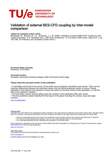
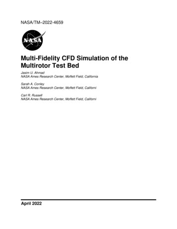
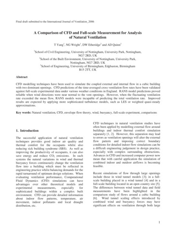
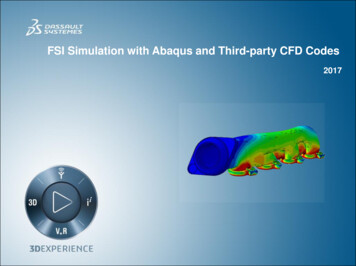
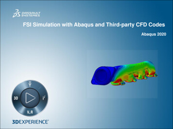
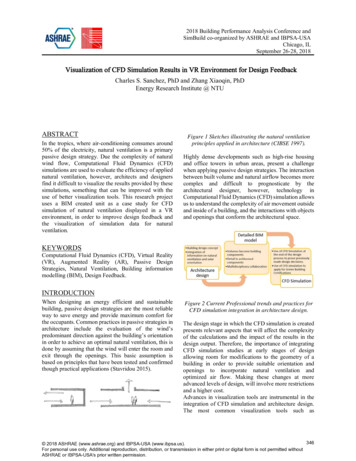
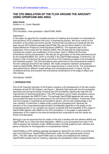
M&C 2017 - International Conference on Mathematics & Computational Methods Applied to Nuclear Science & Engineering,Jeju, Korea, April 16-20, 2017, on USB (2017)On the basis of the recommended guidance in the CFDcode theory guide, when the y lies higher than laminarsub-layer limit of 30, the wall function is suitable. For themesh chosen in the present simulation, the average near wally is 63.2. Geometry and mesh generationThe 61-pin wire-wrapped fuel assembly of CEFR issimulated in the present work as shown in Fig.1., whichconsists of triangular-arrayed fuel pins, helical wirewrappers and hexagonal duct. Table I. lists the Geometricparameter values of computational model. The fuelassembly has an active portion that is 450mm long, with ahexagonal duct of 56.6mm in width across flat[11]. Fuel pinis 6 mm in diameter and 6.95mm in pitch, which is helicallywrapped by wire spacers (0.95 mm in diameter and 100mmin a wire pitch). These wire wrappers nearly tangent to fuelpin surfaces provides fastening and spacing, as well asincreasing the flow mixing between gaps formed by the fuelpins. The simulation contains 4.5 pitch heights of the pinbundle.Due to the intricate geometry of the wire-wrappedassembly, a huge number of mesh cells is required, as wellas much computational time. For the adequate prediction offield variables such as secondary flows, high performancecomputers are generally demanded to generate the mesh. Inthe present study, a new mesh generation method wasdeveloped to employ high quality hexahedral mesh withnonuniform density, so as to avoid a large amount oftetrahedral mesh and reduce the modeling time.Firstly, the structured hexahedral mesh of the fuelsubassembly without wire wrappers has been generatedusing the software ICEM CFD. According to the geometricperiodicity, six topologically blocks associated to the spacearound a fuel pin can be rotated and copied to cover all thebundle region or the mesh around one pin can also be pastedto obtain the entire domain mesh. The blocks andhexahedral mesh are shown in Fig. 2, where the dense meshareas are concentrated near the pin walls. The structuredhexahedral mesh shows a good quality of greater than 0.65and a relatively rapid generating speed. The second step isdealing with the mesh of helical spacer wires by sometechniques and functions provided in the CFD code Fluent.Locus equations of wire wrappers are written in the userdefined functions as follows:x A cos (15)y A sin (16)z H 2 (17)where y 2 HFig. 1. Geometry configuration of 61-pin wire-wrapped fuelassembly.Table I. Geometric parameter valuesParameterLength(mm)Lead-to-diameter ratioH/D16.667Pitch-to-diameter ratioP/D1.158Outer diameter D6Triangular Pitch P6.95Length L450Wire diameter Dw0.95Wire pitch H100Width acrossflats Af56.6Width W4.224(18)And then the wire spacers mesh can be marked in theuser defined memory and separated from the whole meshdomain. Fig. 3. presents the separated mesh of all the wirewrappers. In the most previous research, the wire wrapper ischanged to be linearly attached to the pin wall by movingthe wire location or increasing the wire diameter to avoidpoint contact in two dimensions. Due to the wire wrapper ismarked by locus equations and separated from the mesh, thereal geometry of wire-wrapped fuel subassembly could bemaintained as far as possible in the present simulation. Thefinal required calculational mesh with spacer wires deletedis shown in Fig. 4. This mesh technique is obviouslydifferent from the conventional mesh method. With no needto create geometry and generate mesh with the wire wrapper,the new method can easily obtain the complex mesh of wirewrappers and change the geometric parameters in the locusequations to perform the fuel assembly design study.
M&C 2017 - International Conference on Mathematics & Computational Methods Applied to Nuclear Science & Engineering,Jeju, Korea, April 16-20, 2017, on USB (2017)(a) Original mesh distribution in a cross-section planeFig. 4. Final mesh distribution in a cross-section plane of61-pin wire-wrapped fuel subassembly3. Boundary conditions and simulation modelsFig. 2. Original mesh distribution without wire wrappers of61-pin wire-wrapped fuel subassemblyBoundary conditions are present in Fig.5. Sodiumproperties at an averaged temperature744K were specified.Inlet temperature and velocity were specified at 633.15 Kand 4.5 m/s, respectively. A static pressure 0 Pa was set atthe bundle outlet. Constant heat flux of 1872.559 kW/m2was imposed on the fuel pin walls ,while the wire wrapperand hexcan surfaces were taken to be adiabatic. No slipboundary condition is applied on all solid walls. Theturbulence parameters in boundary conditions, 2.655mm forhydraulic diameter and 4.34% for turbulence intensity, werecalculated and adopted.Fig. 3. Separated mesh of all the wire wrappersFig. 5. Calculational boundary conditions(b) Mesh distribution between two pin wallsThe SIMPLE scheme was selected for pressure-velocitycoupling. Second-order scheme was used for thediscretization of governing equations. Reynolds number was33880 and the realizable k–ε model with standard wallfunctions was applied in the simulation. The average outlet
M&C 2017 - International Conference on Mathematics & Computational Methods Applied to Nuclear Science & Engineering,Jeju, Korea, April 16-20, 2017, on USB (2017)temperature and mass flow rates of different cross sectionsincluding inlet and outlet were monitored in the iterativeprocess. When the residual values for the continuity,momentum and transport equations reach 10 -7, 10-8 and 10-6,respectively, and all the monitor variables were constant, theconvergence is declared.4. Grid independency studyAs shown in Table II, the grid independency study wasperformed for the 61-pin wire-wrapped fuel subassemblywith 4.5 helical pitches in two steps . Firstly, the number ofradial mesh between two adjacent fuel pin walls was set tobe 26. Three different axial grid configurations (named A1,A2, A3) were chosen. The averaged outlet temperature wastaken as the target variable and deviations were made bycomparing the result with that of the fine mesh A3.Similarly, the number of axial mesh points was fixed at 151in all different radial meshes R1, R3 and R3 in the next step.It can be seen that results of mesh configuration A2 and R2were very close to those of fine mesh A3 and R3,respectively, which can be considered as a nearly gridindependent solution. Therefore, the mesh with 151 axialpoints and 26 divisions around the adjacent radial distanceof two fuel pin walls was selected in the present simulation,which has a total cells number of 19.35 millions .Table II. The grid independency study for the 61-pin wirewrapped subassemblyThe axial grid was changed (the number ofradial mesh was fixed at 26)Grid name No. of axialNo. of meshmesh eragedDeviation withoutletfine mesh 73--The radial grid was changed (the number ofaxial mesh was fixed at 151)Grid name No. of radial No. of meshmesh ragedDeviation withoutletfine mesh 8---5. Validation calculationIn order to check the accuracy, the numerical method isvalidated by calculating 19-pin wire-wrapped fuel assemblyexperiment performed by Moon-Hyun Chun[12]. The testsection B2 of the 19-pin assembly was 1300mm in lengthwith a helical pitch height of 200mm. Pins of 8mm indiameter were arranged in triangular configuration with apitch of 10.04mm and the wire diameter was 2 mm.Pressure drops were measured and a series of friction factorswere obtained in the water experiment. As shown in TableIII, the predicted friction factors agree well withexperimental data in a wide range of Reynolds number. Forthe laminar region (defined by the Cheng and Todreascorrelation[13]), the CFD predicted values generally lowerthan the experimental data, contrary to results for theturbulent region. It is seen that the maximum deviation is6.66% .Table III. Comparison of friction factors from experimentand CFD calculationReynoldsfexperimental fCFD%error356.520.265473 0.263908 -0.59723.390.145954 623 0.033729 6.6635651.950.030227 0.031201 3.22III. RESULTSTo quantitatively analyze the complex local flowfeatures, the subassembly has to be divided into variousregions. As depicted in Fig. 6., three types of subchannelswere chosen, named interior , edge and corner subchannel,respectively.Fig. 6. Location of three types of subchannels chosen in thepresent study1. Three-dimensional temperature field
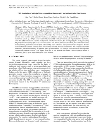
M&C 2017 - International Conference on Mathematics & Computational Methods Applied to Nuclear Science & Engineering,Jeju, Korea, April 16-20, 2017, on USB (2017)As shown in Fig. 7., the temperature in different crosssectional planes increases with axial height. In the samecross-sectional plane, the sodium temperature is higher ininterior zones compared with that in peripheral and cornerregions. The reason can be attributed as follows: the heat isapplied on the fuel pin walls, while hexagonal duct surfacesare set to be adiabatic. The average outlet temperature of theentire subassembly is 831.6K. Fig. 8. depicts area-averagedtemperature distribution at various axial positions. It can beseen that the average temperature in the edge and cornersubchannels presents nonlinear variation with axial height.The average outlet temperature of the interior , edge andcorner subchannel is 908.2K, 773.7K and 762.8K,respectively.(c) y 0.35m(a) y 0.05m(d) y 0.45mFig. 7. Temperature distribution in different cross-sectionalplanes(b) y 0.15mFig. 8. Average temperature distribution along axial heightsin different subchannels
M&C 2017 - International Conference on Mathematics & Computational Methods Applied to Nuclear Science & Engineering,Jeju, Korea, April 16-20, 2017, on USB (2017)2. Three-dimensional flow fieldFig. 9 shows velocity distribution in different crosssectional planes of y 0.35 m, 0.375 m, 0.4 m and 0.425 m.Since the spacer wires are helically wrapped on the fuel pinsalong the axial direction, periodic velocity variation hasbeen observed in different cross-sectional planes. As thecoolant flows upward in the bundle, the region of maximumvelocity shifts from one cross section to the subsequent one.Furthermore, owing to the differences in flow area,hydraulic resistance and orientation of wire spacers, velocitydistribution in the same plane is nonuniform. The velocity inthe edge and corner zones is higher than that in the interiorregion. Different subchannels have a relative positionrelated to the wire wrappers and hexagonal duct surfaces,which imposes an effect on the three-dimensional flowcharacteristics.(c) y 0.4m(a) y 0.35m(d) y 0.425mFig. 9. Velocity distribution in different cross-sectionalplanesAs depicted in Fig. 10., obvious spatially oscillatingflow exists within each subchannel, which results from thepresence of helical wire wrappers. The phase and amplitudeof flow oscillations in the corner and edge subchannelspresent similar distribution, while the flow in interiorsubchannel has smaller phase and amplitude. The peakaverage velocity magnitude in the edge subchannel reaches6.35 m/s. The average velocity magnitude in the corner,edge and interior subchannel is about 1.178, 1.176 and 0.98times of the inlet velocity 4.5 m/s, respectively.(b) y 0.375m
M&C 2017 - International Conference on Mathematics & Computational Methods Applied to Nuclear Science & Engineering,Jeju, Korea, April 16-20, 2017, on USB (2017)Fig. 10. Average velocity magnitude at various axiallocations in different subchannelsFig.11 and Fig.12 show pressure distributions in theplane y 0.325m and x 0m, respectively. Since fuel pins arehelically wound with wire wraps, the pressure displaynonuniform distribution in both cross section and axialdirection section. The average pressure drop in the wholebundle domain is 46.8 kPa.Fig. 12. Pressure distribution in the plane x 0mFig. 13 depicts vector contour of velocity component zin different subchannels. It can be seen that there exists aclockwise transverse swirl flow around the pin walls, whichis in the direction same as that of wire wrappers rotation.Fig. 13. Vector contour of velocity component z in differentsubchannels3. Different subchannel flow behaviorsFig. 11. Pressure distribution in the cross-sectional planey 0.325mThe axial and transverse flow behaviors in the interior,edge and corner subchannels have been investigated in thepresent simulation. The average axial velocity v within 1.4pitch heights in different subchannels is plotted in Fig. 14.Axial flow characteristic of spatially oscillating in the edgesubchannel is nearly similar to that of the corner subchannel,which has a periodicity of one pitch height. The averageaxial velocity in the edge and corner subchannels is about23% higher than that in the interior subchannel. In addition,it can be noted that within an axial length of one pitchheight, the interior subchannel is formed with three wire
M&C 2017 - International Conference on Mathematics & Computational Methods Applied to Nuclear Science & Engineering,Jeju, Korea, April 16-20, 2017, on USB (2017)wrappers wrapped on three fuel pins. Hence, the averageaxial velocity in the interior subchannel periodicallychanges and attains three peak values within one pitch.Fig.16. Average velocity component w within 1.4 pitchsheight in different subchannelsFig. 14. Average axial velocity v within 1.4 pitch heights indifferent subchannelsAverage velocity component u and w (transverse flow)also exhibit spatial fluctuation phenomena shown in Fig.15and Fig.16 . The amplitude and phase shift of flowfluctuation is quite distinct in the interior, edge and cornersubchannels. Transverse flow behaviors of differentsubchannels are closely related to the rotation direction ofwire wrappers and relative position between the wires andhexagonal walls. The cross flow mixing induced by helicalwires has a positive effect on uniform temperaturedistribution in the subassembly. This cross flow effect couldpromote the convective heat transfer and reduces the peakcoolant temperature.Fig. 15. Average velocity component u within 1.4 pitchsheight in different subchannelsThe area-averaged transverse velocity Ut can benormalized by the the inlet axial velocity 4.5 m/s as:UN Utu 2 w2 vinvin(19)The normalized average transverse velocity UN within1.4 pitch heights in different subchannels is depicted inFig.17. The transverse velocity fluctuation is more dominantin the corner subchannel. Wire wrappers induce a maximumtransverse flow velocity of about 30% of inlet axial velocity.The transverse flow effect in the corner and edgesubchannels is stronger than that in the interior subchannel.Fig.17. Normalized average transverse velocity within 1.4pitch heights in different subchannelsIV. CONCLUSIONS
M&C 2017 - International Conference on Mathematics & Computational Methods Applied to Nuclear Science & Engineering,Jeju, Korea, April 16-20, 2017, on USB (2017)Three-dimensional numerical analysis of a 61-pin wirewrapped fuel subassembly has been carried out. In thepresent study, a reliable new mesh generation method wasproposed with reasonable cost and local flow characteristicsin the subassembly were captured. The followingconclusions can be drawn:The average temperature in the edge and cornersubchannel exhibits nonlinear variation with axial height.Periodic velocity variations have been observed in thesubassembly. The velocity magnitude in the edge and cornerzones is higher than that in the interior region.Distinct axial and transverse flow characteristics indifferent subchannels result from the flow area, hydraulicresistance and orientation of wire spacers. The average axialvelocity in the edge and corner subchannels is about 23%higher than that in the interior subchannel. The maximumtransverse flow velocity is about 30% of inlet axial velocity.The transverse flow in corner and edge subchannels isstronger than that in the interior subchannel. Further, thereare one oscillation peak of the average axial velocity in theedge and corner subchannels within one pitch, while threeaxial velocity peaks occur in the interior subchannel.This simulation approach with special mesh techniquescould be extended to investigate the flow and heat transferfeatures and perform design analysis of 217-pin wirewrapped fuel subassembly in the future work.NOMENCLATUREA distance between the center of the fuel fin and wirewrap centerH wire pitchu velocity component in the x directionUN normalized average transverse velocityUt transverse velocityv velocity component in the y direction (axial velocity)vin inlet axial velocityw velocity component in the z directionACKNOWLEDGMENTSThis work was supported by National Natural ScienceFoundation of China (Grant No. 11605131).REFERENCES1. Wei Wang. The introduction of chinese demonstrationfast reactor project[J]. Nuclear safety, 2011, 2:76-78.2. IAEA. Status of Fast Reactor Research and TechnologyDevelopment [R]. IAEA-TECDOC-1691. Vienna :International Atomic Energy Agency, 2012.3. Kazumi Aoto, Philippe Dufour, Yang Hongyi, et al. Asummary of sodium-cooled fast reactor development[J].Progress in Nuclear Energy,77(2014):247-265.4. Raza W, Kim K Y. Comparative analysis of flow andconvective heat transfer between 7-pin and 19-pin wirewrapped fuel assemblies[J]. Journal of Nuclear Scienceand Technology, 2008, 45(7): 653-661.5. Pointer W D, Thomas J, Fanning T, et al. RANS-basedCFD simulations of sodium fast reactor wire-wrappedpin bundles[J]. Proceedings of M&C, 2009, 9.6. Hamman K D, Berry R A. A CFD simulation process forfast reactor fuel assemblies[J]. Nuclear Engineering andDesign, 2010, 240(9): 2304-2312.7. Sreenivasulu C T, Prasad C B. Flow and heat transfercharacteristics in a seven tube-bundle wrapped withhelical wires[J]. International Journal of Advancementsin Technology, 2011.8. Jeong J H, Yoo J, Lee K L, et al. Three-dimensionalflow phenomena in a wire-wrapped 37-pin fuel bundlefor SFR[J]. Nuclear Engineering and Technology, 2015,47(5): 523-533.9. Raj M N, Velusamy K. Characterization of velocity andtemperature fields in a 217 pin wire wrapped fuel bundleof sodium cooled fast reactor[J]. Annals of NuclearEnergy, 2016, 87: 331-349.10. ANSYS, 2009. Ansys Fluent 12.0 Theory Guide. FluentInc., Lebanon, NH.11. Yizhe Liu, Yu Hong. Thermal-hydraulic analysis of fuelsubassemblies for sodium cooled fast reactor [J]. AtomicEnergy Science and Technology, 2008, 42(2): 128-134.12. Chun Moon-Hyun, Kyong-Won Seo. An experimentalstudy and assessment of existing friction factorcorrelations for wire-wrapped fuel assemblies [J].Annals of Nuclear Energy, 17 (2001): 1683-1695.13. Cheng S K, Todreas N E. Hydrodynamic models andcorrelations for bare and wire-wrapped hexagonal rodbundles—bundle friction factors, subchannel frictionfactors and mixing parameters[J]. Nuclear engineeringand design, 1986, 92(2): 227-251.
using the software ICEM CFD. According to the geometric periodicity, six topologically blocks associated to the space around a fuel pin can be rotated and copied to cover all the bundle region or the mesh around one pin can also be pasted to obtain the entire domain mesh. The blocks and hexahedral mesh are shown in Fig. 2, where the dense mesh