Transcription
International Journal of Advanced Mechanical Engineering.ISSN 2250-3234 Volume 8, Number 1 (2018), pp. 251-262 Research India Publicationshttp://www.ripublication.comCFD Analysis of Semi-Circular Rib Roughened SolarAir HeaterYadaba Mahanand 1, Abhijit Mahato 2 and Debanshu Shekhar Khamari312Government College of Engineering Kalahandi,Abacus Institute of Engineering and Management, Mogra,3Government College of Engineering Kalahandi,ydb.gcek2016@gmail.com, mahatoa79@gmail.com, debanshushekhar@gmail.comAbstract:The 2D heat transfer and fluid flow phenomenon through an artificially roughenedsolar air heater is investigated by means of a numerical model at a constant heat fluxof 1000 W/m2. A modern CFD code ANSYS FLUENT v 14.5 is used to simulatefluid flow and heat transfer through the solar air heater. The duct wall, Absorber plateand roughness materials are assumed to be homogeneous & isotropic and also thethermal conductivity is independent of temperature. The present work show that theRenormalization-group k-epsilon model provides the results close to those, workedout from available empirical co-relation for two-dimensional steady flow solar airheaters. The maximum enhancement of average Nusselt number has been found to be2.3104 times that of smooth duct for relative roughness pitch of 7.14 and for relativeroughness height of 0.042.Keywords: CFD Analysis; Absorber plate; Solar air heaters; Nusselt number;Friction factor; Reynolds number.Nomenclature:DHydraulic diameter of duct, mmPhWetted perimeter, mmACross-sectional area, m2hHeat transfer coefficient, W/m2KkThermal conductivity of air, W/mKmMass flow rate, kg/sfFriction factor
252Yadaba Mahanand, Abhijit Mahato and Debanshu Shekhar KhamariNuNusselt numberPrPrandtl numberReReynolds numberL1Entrance length of duct, mmL2Test length of duct, mmL3Exit length of duct, mmWWidth of duct, mmHDepth of duct, mmeRib height, mmPRib Pitch, mmW/HDuct aspect ratioI. INTRODUCTION AND LITERATURE SURVEYSolar air heaters with artificial roughness in the form of fine wires of differentshapes, sizes and orientations on the underside of the absorber plate is one of theimportant and effective design improvement that have been proposed to improve thethermal performance. Artificial roughness has been used to enhance the heat transfercoefficient by creating turbulence in the flow. However it would also result in anincrease in friction losses and hence greater pumping power requirements for airthrough the duct. In order to keep the friction losses at a low level, the turbulencemust be created only in the region very close to the duct surface .i.e. in the laminarsub-layers.The concept of artificial roughness was first applied by Joule [1] to enhance heattransfer coefficients for in-tube condensation of steam and since then manyexperimental investigations were carried out on the application of artificial roughnessin the areas of cooling of gas turbine, electronic equipment, nuclear reactors, andcompact heat exchangers etc. Nunner [2] was the first who developed a flow modeland likened this model to the temperature profile in smooth tube flow at increasedPrandtl number. The proposed flow model predicts that roughness reduces the thermalresistance of the turbulence dominated wall region without significantly affecting theviscous region. A friction correlation for flow over sand-grain roughness wasdeveloped by Nikuradse. Based on law of the wall similarity, Nikuradse [3] presentedthe pressure drop results in terms of roughness function R and roughness Reynoldsnumber e . Dipprey and Sabersky [4] developed a heat-momentum transfer analogyrelation for flow in a sand-grain roughened tube and achieved excellent correlation oftheir data. The concept proposed by Dipprey and Sabersky was so common and it canbe applied to any roughness for which law of the wall similarity holds. Prasad andMullick [5] were the first who introduced the application of artificial roughness in theform of small diameter wire attached on the underside of absorber plate to improve
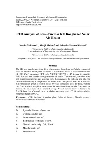
CFD Analysis of Semi-Circular Rib Roughened Solar Air Heater253the thermal performance of solar air heater for drying purposes.II. CFD INVESTIGATION:The CFD code ANSYS ANSYS FLUENT v 14.5 has been used to simulatefluid flow and heat transfer, and also to solve the various conservation equations formass, momentum and energy. Computational domain, mesh generation, governingequations, boundary conditions, selection of suitable turbulence model and solutionprocedure is discussed in details to the following sub-sections.a. Computational domainThe computational domain (2D model) design and simulation for the study ofartificial roughness in solar air heater is in accordance with the ASHRE 93-2003.According to these standard entire flow field is divided into three sections i.e. Entrysection, Test section and Exit section respectively. The first section is the entrysection and is provided so that the flow will be fully developed before test section.The exit section which is provided to make sure that the effect of flow exit is notaffecting the test section. The geometric model developed for current study is asshown below.Fig. 1 Computational domain for smooth absorber plate solar air heaterFig. 2 Computational domain for roughened absorber plate solar air heater
254Yadaba Mahanand, Abhijit Mahato and Debanshu Shekhar KhamariTable 1 Geometrical and operating parameters for computational analysisEntrance length of duct, L1Test length of duct, L2Exit length of duct, L3Width of duct, WDepth of duct, HHydraulic diameter of duct, DDuct aspect ratio, W/HRib height, eRib Pitch, PReynolds number, b. Mesh generationNon-uniform grids are generated for all numerical simulations performed inthis work. Non-uniform grids are commonly used in modeling when large gradientsare expected, local details are desired, or complex geometries are encountered.Automatic (patch conforming) non-uniform grids are generated for all numericalsimulations performed in this work. Grids are generated using ANSYS ICEM CFDV14.5 software. A non-uniform mesh with very fine mesh size is used to resolve thelaminar sub-layer and is shown in fig.2. Since low-Reynolds-number turbulencemodels are employed, the grids are generated so as to be fine. Present non-uniformquadrilateral mesh contained 95,483 quad cells with cell size of0.2mm. This size is suitable to resolve the laminar sub-layer. For grid independencetest, the number of cells is varied from 54,272 to 1, 93,288 in five steps.Fig. 3 2D closed mesh view
CFD Analysis of Semi-Circular Rib Roughened Solar Air Heater255c. Governing EquationThe phenomenon of flow for an artificially roughened solar air heater duct is ruled bythe steady 2-dimensional form of continuity, Navier-Stokes equation and energyequation. In Cartesian co-ordinate system these equations can be written as(i)Continuity Equation: (𝜌𝑢𝑖 ) 0 𝑥𝑖(ii)(2.1)Momentum Equation: 𝑥𝑖 𝑝 𝑢 𝑢 (𝜌𝑢𝑖 𝑢𝑗 ) 𝑥 𝑥 [𝜇 ( 𝑥 𝑖 𝑥𝑗)] 𝑥 ( 𝜌𝑢𝑖′ 𝑢𝑗′ )𝑖𝑗𝑗𝑖(2.2)𝑗(iii) Energy Equation: 𝑥 (𝜌𝑢𝑗 𝑇) 𝑥 (( 𝑗 𝑇) 𝑥 )(2.3)𝑗Whereandare molecular thermal diffusivity and turbulent thermaldiffusivity, respectively and are given by𝜇 𝑃𝑟And𝜇 𝑃𝑟𝑡(2.4)𝑡d. Boundary ConditionThe inlet velocity of the flow is calculated by using Reynolds number. Theoutlet boundary condition is specified at the exit of the computational domain. At exitoutlet boundary condition is applied atmospheric pressure (1.013 x 10⁵ Pa). Table 2shows the Thermo-physical properties of air and aluminium absorber plate. Table 3shows Boundary condition of study domain.Table 2 Thermo-physical properties of air and aluminium absorber plate forcomputational analysisPropertiesWorking fluid(air)Absorber plate(aluminium)Density (ρ) (kg/m3)1.2252719Specific heat (Cp) (J/kg-K)1006.43871Thermal conductivity (k) (W/m//K)0.0242202.4Viscosity (µ) (N/m2)1.7894*10-5-
256Yadaba Mahanand, Abhijit Mahato and Debanshu Shekhar KhamariTable 3 Boundary condition of study domainSurfaceBoundary ConditionValueInletInlet VelocityCalculated from ReOutletOutlet PressureAtmospheric PressureTop SurfaceAbsorber plateHeat Flux of 1000w/𝑚2Bottom SurfaceWallInsulatedIII. RESULTS AND DISCUSSIONSa.Validation of CFD modelThe selection and validation of turbulence model is carried out by comparing theNusselt number predicted by different turbulence model such as standard k-𝜀 model,Renormalized group k-𝜀 model (RNG) with empirical correlation available forsmooth duct of the solar air heater i.e. Dittus-Boelter correlation.Fig.4 compare the variation of Nusselt number with Reynolds number usingdifferent turbulence model and results obtained from Dittus-Boelter empiricalcorrelation for a smooth duct of solar air heater. For low Reynolds number (relevantin solar air heater), it has been observed that the results obtained by theRenormalization Group (RNG) k- 𝜀 model are good agreement with the DittusBoelter empirical correlation results. This ensures the accuracy of the numerical dataobtained from the present work.Fig.4 Comparison between Nusselt number predictions using different turbulencemodel with Dittus-Boelter correlation for smooth duct.
CFD Analysis of Semi-Circular Rib Roughened Solar Air Heater257The Table 4 and 5 show that how the Nusselt Number enhancement factor changeswith respect to Reynolds number for different values of P/e and e/D ratio and theFriction factor enhancement ratio Respectively which is predicted from CFDinvestigation.Table 4 Nusselt number Enhancement ratio predicted by CFD analysisNusselt Number Enhancement Ratioe/D P/e Re 3800 Re 5000 Re 8000 Re 12000 Re 15000 Re 1800014.29 1.45111.4790231.49411.523891.538171.55530.021 21.43 1.42059 1.450298 1.475691.500081.528781.5241228.57 1.408891.433391.45461.472781.5116681.458235.71 1.35732 1.402158 1.408824 1.446391.460371.408410 1.783717 1.7959781.83281.85601.873981.88480.03 151.73871.767891.78651.81621.851091.8656201.71795 1.7415688 011.80751.8197.14 2.20972.25312.26742.27392.290672.31040.042 10.71 2.086542.109072.17992.194832.050732.1755514.29 2.03342.07322.11932.13842.03362.100917.85 1.9802.03352.09062.09062.04372.0708Table 5 Friction factor enhancement ratio predicted from CFD 71101520257.1410.7114.2917.85Re 3682.43223.12062.70152.44592.350Re 2.417053.10872.67142.425632.309Friction factor enhancement ratioRe 8000 Re 12000 Re 15000 Re 2.11091.96439 1.978022.04391.906561.867588 1.9192 2.46772.44862.44492.45752.44912.42352.41099 2.419592.39862.380693.07156 3.04832 3.014093.012972.66512.6593 130932.2552
258Yadaba Mahanand, Abhijit Mahato and Debanshu Shekhar KhamariThe effect of Relative roughness pitch P/e on Heat transfer has been shown typicallyin Fig.5 and Fig.6. Fig.5 (a, b and c) shows that the Nusselt number increases withincrease in Reynolds number for all cases. It can be seen from Fig6 (a, b and c) showsthat the Nusselt number as a function of Relative roughness pitch (P/e) for differentvalues of Reynolds number and for fixed (a) e/D 0.021,(b)e/D 0.03 and(c)e/D 0.042. It can be seen that for a given Relative roughness height Nusseltnumber decreases with an increase in Relative roughness pitch. This is due to fact thatwith the increase in Relative roughness pitch number of reattachment point reduces.The maximum enhancement of average Nusselt number has been found to be 2.3104times that of smooth duct for relative roughness pitch of 7.14 and for relativeroughness height of 0.042.(a)(b)(c)Fig 5 (a, b and c) Nusselt number as a function of Relative roughness pitch (P/e)for different values of Reynolds number for fixed (a) e/D 0.021, (b)
CFD Analysis of Semi-Circular Rib Roughened Solar Air Heater(a)259(b)(c)Fig 6 (a, b and c) Friction factor as a function of Reynolds number for differentvalues of P/e and for fixed (a) e/D 0.021, (b) e/D 0.03 and (c) e/D 0.042.It is found that thermal enhancement factor value vary between 1.1 to 1.65 for therange of parameter investigated. It is observed that roughened duct having semicircular rib with e/d 0.042 and P/e 14.29 gives the better thermal enhancement factorfor the studied range of Reynolds number. Fig 6 shows that the variation of thermalenhancement factor with Reynolds number for all cases
260Yadaba Mahanand, Abhijit Mahato and Debanshu Shekhar KhamariFig.7 variation of Thermal Enhancement factor with Reynolds number for differentvalues of relative roughness height (e/D) and relative roughness pitch (P/e).b.Validation of resultsFig. 8 shows the validation of present analysis of artificially roughened solar airheater having semi-circular rib roughness.Fig. 8 Comparison between present CFD result and previous experimental resultwhich was carried out in Circular rib roughened solar air heater under similar flowcondition
CFD Analysis of Semi-Circular Rib Roughened Solar Air Heater261Table 6. Compares the operating parameters range with previous accepted rangeWidely acceptedShape of ribsnumerical resultsYadav and Bhagoria(14) Circular transverse wire ribYadav and Bhagoria(15)Square sectioned ribChaube et al.Rectangular sectioned ribPresent CFD studySemi-circular sectioned ribRangeP/e 10.71 and e/D 0.042P/e 10.71 and e/D 0.042P/e 13.33 and e/D 0.042P/e 14.29 and e/D 0.042IV. CONCLUSIONThe effects of Reynolds number, relative roughness pitch and relative roughnessheight on the heat transfer and fluid flow process are discussed. Key findings from thestudy are as follows:1. The Renormalization-group (RNG) k-epsilon turbulence model predicted veryclose results to the experimental results, which yields confidence in thepredictions done by numerical analysis in the present study.2. The maximum enhancement of average Nusselt number has been found to be2.3104 times that of smooth duct for relative roughness pitch of 7.14 and forrelative roughness height of 0.042.3. The maximum enhancement of average friction factor has been found to be3.12 times that of smooth duct for relative roughness pitch of 7.14 and forrelative roughness height of 0.042. The maximum enhancement of averagefriction factor occurs at a Reynolds number of 3800.REFERENCES[1]J.P. Joule,“On the surface condensation of steam”, Philosophical Transactionsof the Royal Society of London, 151:133-60; 1861[2]W. Nunner,“Heat transfer and pressure drop in rough pipes”, vol. 22. VDIForsch, 1956, 445-B, English Trans, AERE Lib / Trans; 786; 1958.[3]J. Nikuradse,“Laws of flow in rough pipes”, NACA Technical Memorandum,1292; 1950.[4]D.F. Dippery, R.H. Sabersky,“Heat and momentum transfer in smooth andrough tubes at various Prandtl number”, International Journal of Heatand Mass Transfer, 6:329-53; 1963.[5]K. Prasad, S.C. Mullick,“Heat transfer characteristics of a solar air heater usedfor drying purposes”, Applied Energy, 13(2):83-93; 1983.[6]R. Karw, S.C. Solanki, J.S. Saini,“Thermo-hydraulic performance of solar airheaters having integral chamfered rib roughness on absorberplates”, Energy, 26:161-76; 2001.
262Yadaba Mahanand, Abhijit Mahato and Debanshu Shekhar Khamari[7]R.P. Saini, J. Verma,“Heat transfer and friction factor correlations for a ducthaving dimple-shaped artificial roughness for solar air heaters”,Energy, 33; 1277-87; 2008.[8]S. Singh, S. Chander, J.S. Saini,“Heat transfer and friction factor correlationsof solar air heater ducts artificially roughened with discrete V-downribs”, Energy, 36:5053-64; 2011.[9]J.L. Bhagoria, J.S. Saini, S.C. Solanki,“Heat transfer coefficient and frictionfactor correlations for rectangular solar air heater duct havingtransverse wedge shaped rib roughness on the absorber plate”, RenewableEnergy, 25:341-69; 2002.[10]B.E. Launder, D.B. Spalding, Lectures in Mathematical Models ofTurbulence, Academic Press, London, England, 1972.[11]V.S. Hans, R.P. Saini, J.S. Saini, Heat transfer and friction factor correlationsfor a solar air heater duct roughened artificially with multiple V-ribs, Sol.Energy 84 (2010), 898e911.[12]M. Sethi, Varun, N.S. Thakur, Correlations for solar air heater duct withdimpled shape roughness elements on absorber plate, Sol. Energy 86 (2012)2852e2861.[13]B. E. Launder, and D. B. Spalding, Lectures in Mathematical Models ofTurbulence, Academic Press, London, 1972.[14]S. V. Patankar, Numerical Heat Transfer and Fluid Flow, Hemisphere,Washington, D.C. 1980.[15]S. W. Ahn, The Effects of Roughness Types on Friction Factors and HeatTransfer in Roughened Rectangular Duct, Int. Comm. in Heat and MassTransfer, vol. 28, no. 7, pp. 933–942, 2001.[16]A. Chaube, P. K. Sahoo, and S. C. Solanki, Analysis of Heat TransferAugmentation, and Flow Characteristics due to Rib Roughness over AbsorberPlate of a Solar Air Heater, Renewable Energy, vol. 31, pp. 317–331, 2006.[17]Prasad BN, Saini JS. Effect of artificial roughness on heat transfer and frictionfactor in a solar air heater. Solar Energy 1988;41(6):555e60.
Grids are generated using ANSYS ICEM CFD V14.5 software. A non-uniform mesh with very fine mesh size is used to resolve the laminar sub-layer and is shown in fig.2. Since low-Reynolds-number turbulence models are employed, the grids are generated so as to be fine. . CFD Analysis of Semi-Circular Rib Roughened Solar Air Heater 255