Transcription
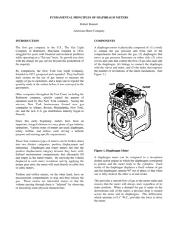
FUNDAMENTAL PRINCIPLES OF DIAPHRAGM METERSRobert BennettAmerican Meter CompanyINTRODUCTIONCOMPONENTSThe first gas company in the U.S., The Gas LightCompany of Baltimore, Maryland, founded in 1816,struggled for years with financial and technical problemswhile operating on a "flat rate" basis. Its growth was slowwith the charge for gas service beyond the pocketbook ofthe majority.A diaphragm meter is physically composed of: (1) a bodyto contain the gas pressure and form part of thecompartments that measure the gas, (2) diaphragms thatmove as gas pressure fluctuates on either side, (3) valvecovers and seats that control the flow of gas into each sideof the diaphragm, (4) linkage to connect the diaphragmwith the valves and index, and (5) the index that registersthe number of revolutions of the entire mechanism. (SeeFigure 1.)By comparison, the New York Gas Light Company,founded in 1823, prospered and expanded. They had builttheir system on the use of gas meters to measure thesupply of gas to customers, and a large one to register thequantity made at the station before it was conveyed to thegasometers.Other companies throughout the East Coast, including theBaltimore company, quickly copied the pattern ofoperation used by this New York company. Seeing thesuccess, New York businessmen formed new gascompanies in Albany, Boston, Philadelphia, New York,etc. and the new U.S. gas distribution industry began toflourish.Since this early beginning, meters have been animportant, integral element in every phase of gas industryoperations. Various types of meters are used; diaphragm,rotary, turbine, and orifice; each serving a definitepurpose and meeting specific requirements.These four common types of meters can be broken downinto two distinct categories: positive displacement andinferential. Diaphragm and rotary meters fall into thepositive displacement category because they have welldefined measurement compartments that alternately filland empty as the meter rotates. By knowing the volumedisplaced in each meter revolution and by applying theproper gear ratio, the meter will read directly in cubic feetor cubic meters.Turbine and orifice meters, on the other hand, have nomeasurement compartments to trap and then release thegas. These meters are inferential meters in that thevolume passing through them is "inferred" by observingor measuring some physical characteristic.Figure 1. Diaphragm MeterA diaphragm meter can be compared to a two-pistondouble-action engine in which the diaphragms correspondto pistons and the meter body to the cylinders. Eachstroke of the diaphragm displaces a fixed volume of gasand the diaphragms operate 900 out of phase so that whenone is fully stroked, the other is at mid-stroke.This provides a smooth flow of gas to the meter outlet andensures that the meter will always start, regardless of itsstatic position. When a demand for gas is made on thedownstream side of the meter, a pressure drop is createdacross the meter and its diaphragms. This differential,which amounts to 0.1" W.C., provides the force to drivethe meter.
Figure 3. Tangent AdjustmentsSTANDARDSFigure 2. Movement of a Diaphragm MeterAbove each diaphragm is a "D" shaped valve (See Figure2.). Under the valve are three port openings that directthe flow of gas in and out of the case and diaphragmcompartments. As the diaphragm expands, it forces thegas in the case compartment up through the case port.The valve directs the flow of gas into the center port thatleads to the meter outlet. A similar process occurs whenthe diaphragm contracts. The stroke of the diaphragm iscontrolled by linkage in the upper port of the meter and arod (flag rod) that extends down into the diaphragmcompartment. The tangent link, as it is called, is attackedto the top of the meter crank and is adjustable in length.Increasing the tangent length increases the diaphragms’stroke, which increases the meter proof and vice versa(See Figure 3.)To provide some common base for rating the capacity ofvarious manufacturers’ gas meters, the ANSI B109.1 gasmeter standard establishes a set of guidelines for meterswith a capacity of less than 500 cubic feet per hour.ANSI B109.2 is the standard for diaphragm metershandling more than 500 cubic feet per hour and ANSIB109.3 covers the "Rotary Type Gas DisplacementMeter."Both B109.1 and B109.2 define diaphragm-type gasmeter capacity as that volume of 0.60 specific gravity gasat an absolute pressure of 14.73 PSIA that will result in anaverage pressure drop through the meter of 0.5 inch ofwater column, using specified inlet and outletconnections. This capacity rating is not to be construed asa maximum capacity but as a common capacity ratingbase. Within the B109.1, meters are divided up intoseveral classes:ClassThe crank makes a certain number of turns per cubic footand transmits this motion to the front counter (index) bymeans of an axle shaft driven by a worn and wheel. Thecrank also drives the sliding valves, which are timed tothe motion of the diaphragm.50174250400Capacity (ft3/hr)MinimumMaximum50174175249250399400499This standard calls for new meters to be 1.0% accurateand 2.0% after accelerated life tests. (See Figure 4. forsmall meter test apparatus.)
Diaphragm meters meeting the requirements of bothB109.1 and B109.2 will measure the gas flow to a pilotlight starting at .25 ft3/hour for a Class 250 meter andsmaller and up to 7 ft3/hour for a class 3500. Theallowable accuracy at this flow is 10%. A typicalaccuracy curve for a diaphragm meter is shown in Figure6.Figure 6. Diaphragm Meter AccuracyFigure 4. Test ApparatusThe B109.2 (500 Cubic Feet or More) also divides largevolume meters into several classes.Class500900140023003500Capacity 49935005599In addition to the capacity of the meter, its body must bephysically constructed to withstand the internal pressureof the gas. Modern diaphragm meters have sufficientstructural integrity to withstand a minimum shell test of10 PSI. This is necessary to meet the federal rulescontained in Part 192 of Title 49, Department ofTransportation, Office of Pipeline Safety regulations.The end connections must be of sufficient size to alloweasy passage of gas through the meter and can be sometype of insert, NPT screw connections, or flanges. (SeeTable 1 for capacities and connections.)(Figure 5. shows a typical test stand used to determinemeter capacities for large volume meters.)Table 1. Diaphragm Meter CapacitiesFigure 5. Large Meter Test Apparatus
INSTALLATIONHand-tighten the swivels first and then tighten with awrench approximately three flats (approximately 20 ft-lb).Do not over tighten since damage to the rubber gasketinside the swivel cap may occur.Check all connections for leaks.Slowly pressurize the system.MAINTENANCEThe diaphragm meter really does not require muchmaintenance other than a periodic proof test. Factors thataffect meter accuracy include:Figure 7. Typical Diaphragm Meter InstallationDiaphragm meters should always be shipped, stored, andinstalled in an upright position. Dust caps on the inlet andoutlet connections should be left in place until the meter isinstalled. Caution should be used with meters that havebeen removed from service since they may contain gaswithin the diaphragm chambers.The meter set should be in a location that is ventilated andreadily accessible for examination, reading, replacement,or maintenance. The set should be protected from outsidedamage and at least three (3) feet from known sources ofignition or air intakes. Electrical isolation for cathodicprotection purposes should be maintained.A diaphragm meter should be installed as close to level aspossible. Tests have indicated that tilting a meter willaffect its accuracy since, at high angles, the valves tend tocome off the valve seat and let the gas bypass thediaphragm chambers. Therefore, the inlet and outletconnections should be within 1/4" of each other.The meter should be installed in a manner to avoid unduestress on the connecting piping or meter. The use of ameter bar may be a consideration. If there is foreignmaterial such as sand, rust scale, or welding beads in thegas supply; then a filter or strainer should be provided onthe inlet side. The meter should not be installed at thelow point since it may act as a trap for liquids. By-passpiping or some other type of testing components, pressuretaps, and over-speed protection should be considered.Avoid having the meter body come in direct contact withsoil or concrete walls since alkali in concrete can causepremature corrosion. Under no circumstances should themeter be buried.1. Internal Friction that increases meter differential.Excessively dirty or tacky valves or binds in themeter will cause higher differential pressures.2. Maintaining Constant Diaphragm Displacement.A precise and stable diaphragm displacement isrequired for each stroke of the meter. Therefore,the effective cross-sectional area of the diaphragmand the diaphragm stroke must remain constant.3. External Leaks. Any opening, such as covergaskets, index seal box, or meter connections, thatlets gas escape will adversely affect its accuracy.4. Internal leaks will cause the meter to run slow andare usually found in areas such as the diaphragmassembly, valves, or flag rod seals.5. Wear can affect accuracy in several ways. Wearat either end of the short flag arm or in the tangentbearing will cause the check rate proof to decreasewhile not appreciably affecting the open rateproof. Wear of the crank or crank arms will affectthe timing of the valves that will increase the openrate proof.To determine the accuracy of a diaphragm meter, it mustbe tested or proved using conventional testing equipmentsuch as a transfer prover bell, or sonic nozzle or. (SeeFigure 8 for examples.)a. Transfer Prover
REFERENCESGas Measurement Manual, Part Two, DisplacementMeasurement, American Gas Association, 1985.ANSI B109.1, 2000, Diaphragm Type Gas DisplacementMeters, American gas AssociationANSI B109.2, 2000, Diaphragm Type Gas DisplacementMeters, American Gas AssociationANSI B109.3, 2000, Rotary Type Gas DisplacementMeters, American Gas AssociationProduct Specification, Aluminum Case Meter, DomesticSize, American Meter Companyb. Bell Proverc.Sonic NozzleFigure 8. Proving MethodsCONCLUSIONDiaphragm positive displacement meters are and willcontinue to play a major role in natural gas measurementin the U. S. for the foreseeable future. Understandinghow they work, their specifications, and how to installand maintain them are critical to having them perform inan acceptable manner.
ANSI B109.2 is the standard for diaphragm meters handling more than 500 cubic feet per hour and ANSI B109.3 covers the "Rotary Type Gas Displacement Meter." Both B109.1 and B109.2 define diaphragm-type gas meter capacity as that volume of 0.60 specific gravity gas at an absolute pressure of 14.73 PSIA that will result in an