Transcription
COREMetadata, citation and similar papers at core.ac.ukProvided by ZENODONOVATEUR PUBLICATIONSINTERNATIONAL JOURNAL OF INNOVATIONS IN ENGINEERING RESEARCH AND TECHNOLOGY [IJIERT]ISSN: 2394-3696VOLUME 4, ISSUE 6, June-2017CFD ANALYSIS ON RADIALCOOLING OF GAS TURBINE BLADEHARSHA D APG Student, Department of Aerospace Propulsion Technology,VTU, CPGS, Bengaluru Region VIAT,Muddenahalli, India harshaubdtmech@gmail.comDR.YOGANANDA AAssociate Professor, Department of APTVTU, CPGS, Bengaluru RegionVIAT, Muddenahalli, IndiaABSTRACTGas turbines are extensively used for air craft propulsion, land based power generation and industrialapplications. Thermal efficiency of gas turbine improved by increasing turbine rotor inlet temperature. Thecurrent rotor inlet temperature in advanced gas turbine is for above the melting point of blade material. Asophisticated cooling scheme must be developed for continuous safe operation of gas turbines with highperformance. Gas turbines are cooled externally and internally. Several methods have been suggested for thecooling of blades and vanes. The techniques that involve to cool the blades and vanes by using coolingmethods is to have radial holes to pass high velocity cooling air along the blade span. In this thesis, a turbineblade is designed and modelled in CATIA v5 and ICEM CFD software. The turbine blades are designedusing cooling holes. The turbine blade is designed with 12 holes. CFD analysis is done to determine thepressure distribution, velocity, temperature distribution and heat transfer rate by applying the inlet velocities.Thermal and Structural analysis is done to determine the heat transfer rates and strength of the blade. Thepresent used material for blade is chromium steel. In this thesis, it is replaced with Titanium aluminiumalloy. The better material for blade is analyzedKEYWORDS: CFD Analysis, Thermal and Structural analysis, Ansys V15, Radial cooling.INTRODUCTIONWith the advent in Gas turbine technology, its usage as a prime mover has become prominent, since last fewdecades. One of the most important applications of gas turbines is in power generation, though it has been inuse for aircraft propulsion since long time.The efficiency and power output of gas turbine plants is dependent on the maximum temperatures attained inthe cycle. Advanced gas turbine engines operate at high temperatures (1200–15000C) to improve thermalefficiency and power output. With the increase in temperatures of gases, the heat transferred to the bladeswill also increase appreciably resulting in their thermal failure. With the existing materials, it is impossibleto go for higher temperatures. Taking into account the metallurgical constraints, it is necessary to providecooling arrangement for turbine blades to keep their metal temperature with in allowable limits. Therefore,developments in turbine cooling technology play a critical role in increasing the thermal efficiency andpower output of advanced gas turbines.Brahmaiahand Lava Kumar investigated the heat transfer analysis of gas turbine with four different modelsconsisting of blade with without holes and blades with varying number of holes (5, 9&13). The analysis wascarried out using commercial CFD software FLUENT (a turbulence realizable k-є model with enhanced walltreatment) has been used. On evaluating the graphsdrawn for total heat transfer rate and temperaturedistribution, the blade with 13 holes is considered as optimum. Steady state thermal and structural analysiswas carried out using ANSYS software with different blade materials of Chromium steel andInconel718.While comparing these materials Inconel718 is better thermal properties and induced stresses arelesser than the Chromium steelChandrakantet. al compared the performance of helicoidal ducted blade cooling with turbulator of differentgeometric proportion. It was found from analysis that there was significant improvement in coolingcharacteristics for turbine blade with turbulator geometry having larger e/D ratio. Also it was found from hisanalysis, performance has been vastly improved for greater thickness of turbulator geometry. e radialthickness of turbulator rib D outer diameter of helicoidally duct e/D is non dimensional ratio chosen asparametric variable for different configurations of rib geometries.47 P a g e
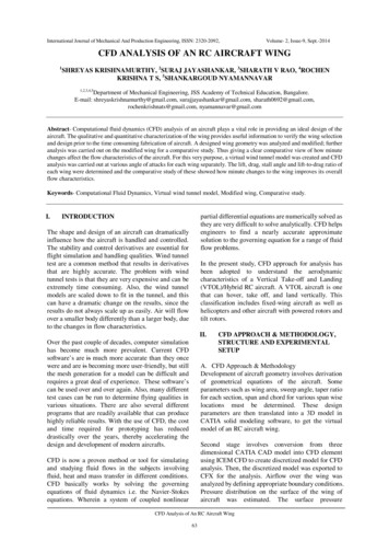
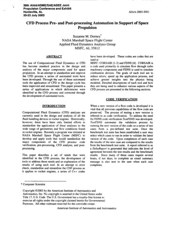
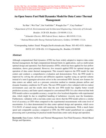
NOVATEUR PUBLICATIONSINTERNATIONAL JOURNAL OF INNOVATIONS IN ENGINEERING RESEARCH AND TECHNOLOGY [IJIERT]ISSN: 2394-3696VOLUME 4, ISSUE 6, June-2017MATHEMATICAL FORMULATION2.1 The physical model Leading Edge Gas Turbine Blade.Fig.1Create blade model with 12 holes3. MESHINGFig.2Geometry model with boundary walls. The model created using CATIA V5 and ICEM CFD software. The whole model is divided into different parts namely inlet, pressure outlet, wall and axis. Global Mesh parameters are defined which gives information regarding type of mesh. The globalelement seed size, part parameters are setup and mesh is computed which gives the mesh informationregarding total number of elements. Anstructured hexahedral mesh is generated in order to perform computations with the Octreeapproach. And unstructured mesh to blade because of the curved shape structure after setting up partparameters for various parts, a mesh is generated with nearly 3093582 elements48 P a g e
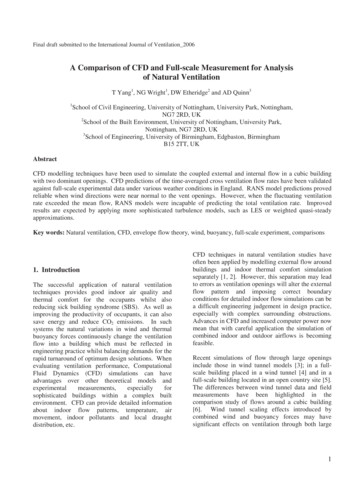
NOVATEUR PUBLICATIONSINTERNATIONAL JOURNAL OF INNOVATIONS IN ENGINEERING RESEARCH AND TECHNOLOGY [IJIERT]ISSN: 2394-3696VOLUME 4, ISSUE 6, June-2017Fig.3Meshed ModelBOUNDARY CONDITIONSThe steps followed for the solver setup is open the Setup option of ANSYS fluent project. Select Solversetup General among solver settings choose the pressure based solver. CFD fluent consist of two solversfor solving the CFD process i.e. pressure based and density based. Here we chooses pressure based; this isbecause the fluid under consideration is air at subsonic speed, where the compressibility effects are smalland can be neglected. Choose the velocity formulation as absolute and time option as steady state.This is because flow is considered to have constant properties with respect to time. Select Solver setup Models Choose energy equation on. Turbine blade analysis is aiming mainly at the temperaturedistribution over the turbine blade. To solve the heat transfer problems the basic energy equation has to beused and this can be used by switching on the energy equation. Select the Realizable K – epsilon model withenhance wall treatment as the viscous model. This is because the hot air velocity is sufficient to make theflow turbulence over the airfoil.The Standard k ɛ is a well-established model capable of resolving through the boundary layer .Select solversetup Materials select fluid and click edit. Edit the properties of the fluid with the properties given thetable click change create. Select solver setup Materials select solid and click edit. Edit the properties ofthe solid with the properties click change create. Select Cell zone conditions and choose the appropriatematerials for the zones like blade, hot air and cold air.Select laminar for the zones of cold air. Click the operating conditions and verify that the operating pressureis 101325 Pascal. This is because we are assuming that this process is simulated at the atmospheric pressureat sea level. Select the boundary conditions and define the boundaries with appropriate input data Accordingto our CFD model the hot air with temperature of 1200 K entering at a velocity of 265 m/s .Similarly thecold air at room temperature of 573 K is entering at a velocity of 30 m/sIn the solution method choose pressure velocity coupling scheme as SIMPLE. , SIMPLE is the acronym ofsemi implicit method for pressure linked equations.Choose momentum, turbulent kinetic energy andturbulent dissipation rate and energy as second order upwind. Second order upwind is the best discretizationmethod for this project since the mesh is made with tetrahedral elements and the flow is not aligned with thegrid. Select the monitors residuals. Click edit. In the dialogue box that appears edit the convergencecriteria of continuity, x velocity, y velocity, z velocity, energy, k, epsilon as 1*10-6. Close the dialogue box.In the solution initialization select the hybrid initialization and click initialize.49 P a g e
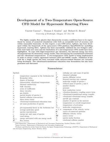
NOVATEUR PUBLICATIONSINTERNATIONAL JOURNAL OF INNOVATIONS IN ENGINEERING RESEARCH AND TECHNOLOGY [IJIERT]ISSN: 2394-3696VOLUME 4, ISSUE 6, June-2017RESULTS AND DISCUSSIONS50 P a g e
NOVATEUR PUBLICATIONSINTERNATIONAL JOURNAL OF INNOVATIONS IN ENGINEERING RESEARCH AND TECHNOLOGY [IJIERT]ISSN: 2394-3696VOLUME 4, ISSUE 6, June-2017CONCLUSIONIn this work, a turbine blade is designed and modelled in CATIA v5 software. The turbine blades aredesigned using cooling holes. The turbine blade is designed with 12 holes. The present used material forblade is Titanium Alloy.Thermal and Structural analysis is done By observing the CFD analysis results, the velocity of mainstream(hot air) is decreased from 12 holes .But the value of pressure is slightly increased. The total heattransfer rate is maximum and the temperature of the leading edge is minimum for the blade consisting of 12holes for titanium aluminum alloyThe temperature of the surface of blade with 12 holes for chromium is minimum. It is found that thetemperature leaving the trailing edge is low leading to decrease in thermal efficiency of gas turbine. Resultshowed that heat transfer coefficient and Nusselt number on the surface of holes are nearly constant for allblade materials with different numbers of holes also the heat transfer coefficient is high at entrance region.REFERENCES1) A. Hasanpour, M. Farhadi and H.R. Ashorynejad , Hole Configuration Effect on Turbine Blade Cooling,World Academy of Science, Engineering and Technology vol 49 2013.2) K Hari Brahmaiah, M. Lava Kumar, Heat Transfer Analysis of Gas Turbine Blade through CoolingHoles , International Journal of Computational Engineering Research (IJCER) 2014.3) Chandrakant R Kini , Computational Conjugate Heat Transfer Analysis of HP Stage Turbine BladeCooling Effect of Turbulator Geometry in Helicoidal Cooling Duct , World Academy of Science,Engineering and Technology Vol:6 20124) B. Deepanraj, Theoretical Analysis of Gas Turbine Blade By Finite Element Method ,Scientific World,Vol. 9, No. 9, July 20115) G Narasa Raju , Steady State Thermal & Structural Analysis of Gas Turbine Blade Cooling System,International Journal of Engineering Research & Technology (IJERT) Vol. 2 Issue 1, January- 201351 P a g e
¾ The model created using CATIA V5 and ICEM CFD software. ¾ The whole model is divided into different parts namely inlet, pressure outlet, wall and axis. ¾ Global Mesh parameters are defined which gives information regarding type of mesh. The global element seed size, part parameters are setup and mesh is computed which gives the mesh .