Transcription
ICEM CFD TutorialSimple Duct GridV1.01ICEM CFD TutorialSimple Duct GridScott J. OrmistonGavin JoyceDepartment of Mechanical EngineeringUniversity of ManitobaWinnipeg, ManitobaCanadaV1.0117 January 2013Department of Mechanical EngineeringUniversity of ManitobaPage 1 of 22
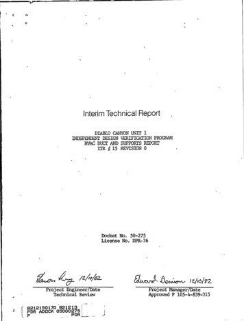
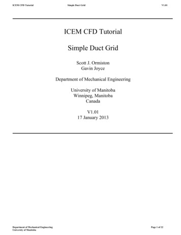
ICEM CFD TutorialSimple Duct GridV1.011. IntroductionThis tutorial will guide you through the creation of a simple duct mesh, and how to export that mesh into a CFXreadable format.1.2 Geometry NomenclatureThe following image shows the basic geometry of the duct.Figure 1: Duct Geometry1.3 OverviewThe following is a summary of the general steps in mesh creation:1. Creation of geometry1.1Create points1.2Use points to define curves1.3Use curves to define surfaces1.4Define the volume or 'body'2. Create parts from surfaces3. Create a block4. Associate the created geometry5. Allocate nodal distribution along the block edges6. Mesh the block7. Create the file needed for input in CFX Pre1.4 SetupIt is highly recommended that you create a new directory to work in. Several files will be created and it is mucheasier to find them later if they are all in a new directory. You can create this new directory while in your rootdirectory or while in any other subdirectory. To do this, you could enter the following commands (% is thecommand prompt):% mkdir icem-tutorial% cd icem-tutorial% pwd/home/u7/umjohndoe/icem-tutorialNote that the ANSYS set of programs (including CFX and ICEM) are unable to read directory names with spacecharacters in them. This means that the name of the new directory and the path leading to the new directorymust not have any spaces. The last line of the above set of commands gives the path and current directorynames; simply ensure there are no spaces.Department of Mechanical EngineeringUniversity of ManitobaPage 2 of 22
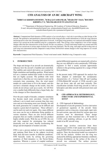
ICEM CFD TutorialSimple Duct GridV1.011.5 Assumptions about Running ICEM CFDIt is assumed that you are logged into a VNCviewer session (or equivalent) or using a Linux/Unix workstation.You must have a graphical interface in order to use ICEM, meaning that you cannot run ICEM through the SSHclient alone. This tutorial was created for ANSYS ICEM CFD version 14.0.Note that throughout the tutorial, unless directed to use the right or middle mouse buttons explicitly, allcommands are to be performed using the left mouse button.1.6 Starting the ProgramStart ICEM CFD by typing the following command in your terminal:% icemcfd'Maximize' the ICEM window by clicking theshould look like this:button at the top right corner of the window. Your screenSome general names for different parts of the ICEM window will be used to help identify where certaincommands are found. The different parts are named the main menu, main buttons, option tabs, optionsbuttons, sidebar, model tree, and view window. These are all labelled in the following image.Department of Mechanical EngineeringUniversity of ManitobaPage 3 of 22
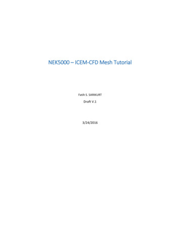
ICEM CFD TutorialSimple Duct GridV1.012. Create the GeometryThe geometry will be created in units of millimetres and then scaled to metres at the output step. Begin thisphase by selecting “Geometry” from the option tabs.2.1 Create points Select 'Create Point' from the option buttons. The new sidebar 'Create Point' will be opened.Within the sidebar, select the 'Explicit Coordinates' button.Department of Mechanical EngineeringUniversity of ManitobaPage 4 of 22
ICEM CFD TutorialSimple Duct GridV1.01 Scroll down the 'Create Point' sidebar. Leave the default setting of 'Create 1 point' and enter the following coordinates:pnt.00X0Y0Z0Then click on Apply. Let the point be created under the part GEOM. The first point will be called 'pnt.00'.Now Geometry and Parts will appear in the model tree. Click on the plus sign to expand theGeometry to get: To see the names of the points right click on points and select “Show point names”. You shouldsee the point with its label “Pnt.00” in the view window.In order to view the remainder of the points as you create them, the following is suggested.Modify the view by selecting View: Department of Mechanical EngineeringUniversity of ManitobaPage 5 of 22
ICEM CFD Tutorial Simple Duct GridV1.01Then, select “Isometric”.Now enter the remaining points shown in the table below. Click Apply each time after enteringthe three coordinate 0Also, after each point is entered, click on the 'Fit Window' from the main buttons (you may needto left click within the view window after pressing 'Fit Window' to enact the change). When all of the points have been entered, click 'Dismiss' in the sidebar. Recall that we havedefined the position of these points 1000 times larger than the geometry dictates (2.0 has become2000) for convenience of working in units that we can think of as mm. We will scale this down by1000 when we create the CFX readable file (our very last step).If you want to change the view of the geometry in the view window you can use the followingmouse controls:Mouse ControlAction PerformedHold down the left mouse button within the view windowand drag in any directionRotate viewHold down the right mouse button within the viewwindow and drag left or rightTilts viewHold down the right mouse button within the viewwindow and drag up or downZooms in or outHold down the middle mouse button within the viewwindow and drag in any directionPans viewScroll the mouse wheel up or down within the viewZooms in or outwindow Familiarize yourself with these controls by experimenting. When you are ready, press ‘FitWindow' from the main buttons and select 'Isometric' from 'View' in the main menu. Your screenshould now look like this:Department of Mechanical EngineeringUniversity of ManitobaPage 6 of 22
ICEM CFD TutorialSimple Duct GridV1.01 We will now save the project. Select 'File' from the main menu, and then select 'Save Project As'. Move to the directory you created in the setup steps of this tutorial and then choose a meaningfulname for this project (for example, ‘duct.prj’) and press 'Save'.Department of Mechanical EngineeringUniversity of ManitobaPage 7 of 22
ICEM CFD Tutorial Simple Duct GridV1.01In the future, save frequently by clicking on the floppy disk icon ('Save Project') in the mainbuttons.2.2 Creating curves/lines Select 'Create/Modify Curve' from the option buttons.The new sidebar 'Create/Modify Curve' will be opened. From within the sidebar select the 'From Points' button. Let the curves be created under partGEOM. Scroll down the 'Create/Modify Curve' sidebar and click on the 'Select location(s)' button. With the left mouse button select points pnt.00 and pnt.01 in the view window, and then click themiddle mouse button. Note that it may be difficult to select the points from the current viewbecause the points are very close together, but you cannot pan or zoom with the mouse normallybecause you are in selection mode. In order to leave the selection mode press F9 on yourkeyboard, and then use the mouse controls normally. Once you have adjusted the current viewsimply press F9 on your keyboard again to return to selection mode.Repeat this process for the remaining eleven lines.Once all of the curves have been created click 'Dismiss' in the sidebar and select 'Fit Window'from the main buttons and 'Isometric' from 'View' in the main menu to display the current Department of Mechanical EngineeringUniversity of ManitobaPage 8 of 22
ICEM CFD TutorialSimple Duct GridV1.01geometry as follows: You can now turn off point names in the model tree by right-clicking the word 'Points' andselecting 'Show Point Names' from the menu that appears.Save the project.2.3 Creating surfaces Select 'Create/Modify Surface' from the option buttons.The new sidebar 'Create/Modify Surface' will be opened. From within the sidebar, select the 'Simple Surface' button. Scroll down the 'Create/Modify Surface' sidebar and click on the 'Select curve(s)' button. Leavethe 'Method' and 'Tolerance' at their default values of 'From 2-4 Curves' and 0.01, respectively.Department of Mechanical EngineeringUniversity of ManitobaPage 9 of 22
ICEM CFD Tutorial Simple Duct GridV1.01With the left mouse button, select four curves that make up a face of the duct geometry. Forexample, the face that is an x-z plane at y 0:Each of the curves should turn white when clicked. If you find that you have clicked on the wrongcurve by mistake, click the right mouse button to unselect it.Now click the middle mouse button, and then press “Apply” in the sidebar (to create surfacesyou must press the middle mouse button and then the apply button, whereas for curves you onlyneeded to press the middle mouse button). As with the creation of curves you can modify yourview while in selection mode by pressing F9 on your keyboard, using the mouse-view controlsnormally, and then pressing F9 again. In order to view the surfaces, click the box beside “Surfaces” in the model tree under“Geometry”. This will show a rough wireframe on the surface that was just created. Thispresentation of a surface contains extra lines that can be confusing when trying to select otherlines for the remaining surfaces. It is suggested that you change the way surfaces are displayed byselecting “Solid/Wire Full Display”:Department of Mechanical EngineeringUniversity of ManitobaPage 10 of 22
ICEM CFD TutorialSimple Duct GridV1.01Your display of the surface that was just created should now look like: Repeat the process of selecting the four curves needed for the remaining five surfaces of the duct.Once all of the surfaces have been created, click 'Dismiss' in the sidebar and select 'Fit Window'from the main buttons and 'Isometric' from 'View' in the main menu to display the currentgeometry as follows:Department of Mechanical EngineeringUniversity of ManitobaPage 11 of 22
ICEM CFD Tutorial Simple Duct GridV1.01Save the project.2.4 Defining the volume or 'body' Select 'Create Body' from the option buttons. The new sidebar 'Create Body' will be opened. From within the sidebar select the 'Material Point' button and fill in both the 'Part' and 'Name' as‘duct’. Leave the default setting of 'Centroid of 2 points' in the 'Location' choice. Within the sidebar, click on the 'Select location(s)' button. Now, in order the see the points that are to be selected, turn off (unclick) Surfaces underGeometry in the model tree.Department of Mechanical EngineeringUniversity of ManitobaPage 12 of 22
ICEM CFD Tutorial Simple Duct GridV1.01With the left mouse button select two points that are on opposite corners of the domain. Forexample, this can be the origin (pnt.00) and the point at x 2000, y 200, and z 300 (pnt.06) in theview window, then press the middle mouse button, and then press 'Apply' in the sidebar. A label“duct” should appear in the middle of the geometry in the view window.Press the 'Dismiss' button in the sidebar. Note that the way we defined this body it is in the centreof the domain and that any two, opposite vertices could have been chosen with the same finalresult. Also, the 'By Topology' option in the 'Create Body' sidebar could have been chosen andeither the entire model or all of the surfaces used to define the body in the centre.You may now turn on the surfaces again in the model tree.Save the project3. Creating Parts Now that the full geometry has been developed, it is helpful to assign meaningful names to thedifferent surfaces. These names will be used when applying boundary conditions to surfaces in CFX.Because we will be selecting only surfaces to create parts, uncheck Points, Curves, and Bodies underGeometry in the model tree.Assigning names to surfaces is done by creating a part for each surface. In the geometry tree rightclick the word 'Parts' and select 'Create Part' from the menu that appears. The new sidebar 'CreatePart' will be opened. Within the sidebar, enter the name 'RCT N' in the 'Part' field and click the 'Create Part by Selection'button. Within the sidebar, click the 'Select entities' button.Department of Mechanical EngineeringUniversity of ManitobaPage 13 of 22
ICEM CFD TutorialSimple Duct GridV1.01 In the isometric view, select the top surface of the geometry (the x-z plane at y 200) in the viewwindow: Press the middle mouse button, and then select 'Apply' in the sidebar. The new part 'RCT N' willnow appear in the geometry under 'Parts'. Uncheck RCT N, so the surface is no longer displayed.Removing RCT N from the view window will make it easier to select the other surfaces.For the remaining five surfaces, follow the procedure above. Remember to uncheck each part as it iscreated. This will also help to know which surfaces are remaining. Assign the following part names to the remaining surfaces:x-y plane at z 300RCT Tx-y plane at z 0RCT Bx-z plane at y 0RCT Sy-z plane at x 0RCT W y-z plane at x 2000RCT EOnce all of the parts are created, press 'Dismiss' in the sidebarCheck Points, Curves, Surfaces, Bodies, and all the new part names in the model tree Save the project.Department of Mechanical EngineeringUniversity of ManitobaPage 14 of 22
ICEM CFD TutorialSimple Duct GridV1.014. Creating a Block Select 'Blocking' from the option tabs.4.1 Create the block Select 'Create Block' from the option buttons. The new sidebar 'Create Block' will be opened. From within the sidebar select the 'Initialize Blocks' button and set the 'Part' field to ‘DUCT’.Leave the 'Type' field as its default '3D Bounding Box'. Reduce the size of the geometry in the view window (by scrolling the mouse scroll button orusing the right mouse button). The image must not be near the edges of the view window becauseyou are going to select all of it next.Click the “Select geometry” button. In the view window, select all of the geometry by clicking, holding, and dragging a box aroundthe entire geometry. Press the middle mouse button and then press 'Apply' in the sidebar. Press'Dismiss' in the sidebar. In the model tree, you should now have a new branch named 'Blocking'.Also in the model tree, under 'Parts', you should have something named 'VORFN'.In the model tree, under 'Geometry', turn off 'Points', 'Curves', and 'Surfaces' so that only 'Bodies'has a check mark next to it. You should see the following after pressing 'Fit Window' andchoosing 'Isometric' from 'View' in the main menu:Department of Mechanical EngineeringUniversity of ManitobaPage 15 of 22
ICEM CFD Tutorial Simple Duct GridV1.01You are seeing the edges of the block. They are coloured white until they are associated with acurve in your geometry.Save the project.5. Doing the Edge Associations5.1 Associate the created geometry to the block Select 'Associate' from the option buttons. The new sidebar 'Blocking Associations' will beopened. From within the sidebar select 'Auto Association'. Leave the default 'Snap Project Vertices' and then press 'Apply' and 'Dismiss' in the sidebar. Youshould see the white lines turn green:Department of Mechanical EngineeringUniversity of ManitobaPage 16 of 22
ICEM CFD Tutorial Simple Duct GridV1.01Note that auto-association can only be used because this is a very simple geometry. For morecomplicated geometries, manual association must be performed.Save the project.6 Nodal Distributions6.1 Allocate nodal distribution along the block edges Select 'Pre-Mesh Params' from the option buttons. The new sidebar 'Pre-Mesh Params' will beopened. From within the sidebar select 'Edge Params'. Click 'Select edge(s)Department of Mechanical EngineeringUniversity of ManitobaPage 17 of 22
ICEM CFD TutorialSimple Duct GridV1.01 Select the edge line the goes from (0,0,0) to (0,0,300) (i.e., from pnt.00 to pnt.01) in the viewwindow. In the sidebar again, enter 16 in the 'Nodes' field and set the 'Mesh law' field to 'BiGeometric'(note that you may have to reselect the curve and enter the number of nodes a second time).Scroll down the sidebar and select 'Copy Parameters' and then set the 'Method' field to 'To AllParallel Edges'. Press 'Apply' and you should now see small red ticks along all the lines in the z-direction. There isalso the number of nodes printed in red.Department of Mechanical EngineeringUniversity of ManitobaPage 18 of 22
ICEM CFD TutorialSimple Duct GridV1.01 You will have to zoom in to see these details clearly. Scroll back to the top of the sidebar and click 'Select edge(s)' again. This time select the line from(0,0,0) to (0,200,0) in the view window and then enter 11 in the 'Nodes' field of the sidebar.Ensure that the 'Mesh law' is still set to 'BiGeometric', the 'Copy Parameters' button is stillhighlighted, and the 'Method' is still set to 'To All Parallel Edges'. Again, press 'Apply' and tickswill appear on all the lines in the y direction.Scroll back to the top of the sidebar and click 'Select edge(s)' again. This time select the line from(0,0,0) to (2000,0,0) in the view window and then enter 41 in the 'Nodes' field of the sidebar.Ensure that the 'Mesh law' is still set to 'BiGeometric', the 'Copy Parameters' button is stillhighlighted, and the 'Method' is still set to 'To All Parallel Edges'. Again, press 'Apply' and tickswill appear on all the lines in the x direction. Press 'Dismiss' in the sidebar.Save the project. Department of Mechanical EngineeringUniversity of ManitobaPage 19 of 22
ICEM CFD TutorialSimple Duct GridV1.017 Meshing the Block Select 'File' from the main menu, then select 'Blocking' and 'Save Unstruct Mesh' in the menus thatappear. Name the file something meaningful like ‘duct’ and press save.Select 'File' from the main menu, then select 'Mesh' and 'Load from Blocking' in the menus thatappear. Wait a moment while the mesh is generated. You can now see your mesh in the view window. When you zoom in there will be a grid around thegeometry.Department of Mechanical EngineeringUniversity of ManitobaPage 20 of 22
ICEM CFD Tutorial Simple Duct GridV1.01Save the project.8 Creating the file for CFXWrite the mesh to an input file for CFX Pre The final step is to create a CFX readable file from the ICEM mesh. To do this, select 'Output' fromthe option tabs. Select 'Select solver' from the option buttons.The sidebar 'Solver Setup' will be opened. In the sidebar, set the 'Output Solver' field to 'ANSYS CFX', the 'Common Structural Solver' field to'ANSYS'. Click 'Apply' and 'Dismiss'.Select 'Write input' from the option buttons. You will be prompted to save the current project first, select 'Yes'A new window with the title 'CFX5' will appear. Highlight 'Yes' in the 'Scaling' field and set the x-, y, and z-scaling factors to 0.001. Note the scaling is necessary because we input dimensions 1000times greater than those dictated by the geometry.Department of Mechanical EngineeringUniversity of ManitobaPage 21 of 22
ICEM CFD Tutorial Simple Duct GridV1.01Click done.CONGRATULATIONS! You have just created a basic mesh using ANSYS ICEM. The .cfx5 file that youcreated can be read into CFX-Pre.Department of Mechanical EngineeringUniversity of ManitobaPage 22 of 22
client alone. This tutorial was created for ANSYS ICEM CFD version 14.0. Note that throughout the tutorial, unless directed to use the right or middle mouse buttons explicitly, all commands are to be performed using the left mouse button. 1.6 Starting the Program Start ICEM CFD by typing the following command in your terminal: % icemcfd