Transcription
NEK5000 – ICEM-CFD Mesh TutorialFatih S. SARIKURTDraft V.13/24/2016
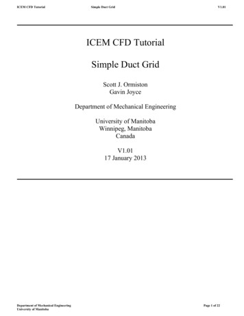
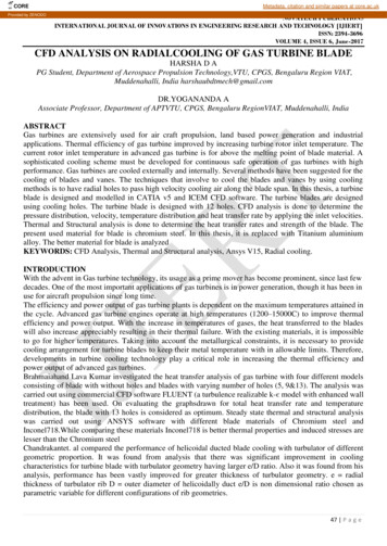
Mesh for Nek5000 by using ICEM-CFD with Boundary ConditionsIn this tutorial, a T-junction geometry is meshed by using ICEM-CFD and applied boundary conditions.Figure 1: T-Junction Geometry blockingStep 1In this step, it is assumed the user is already familiar with ICEM-CFD. The mesh is created by using ablocking strategy to obtain fully hexahedral cells. Once the mesh creation has been done with blockingmethod, the mesh needs to be converted to unstructured mesh as shown in Figure 2 due to the ExodusII format requirement discussed further in Step 4.Figure 2: Conversion to Unstructured mesh
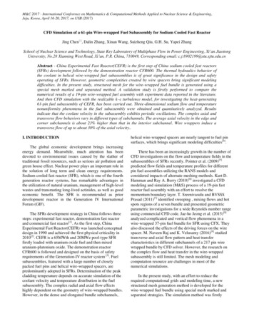
Step 2In this step, the created mesh in step 1 needs middle nodes between each node. Hexa8 can beconverted to Hexa27 in ICEM CFD’s Edit Mesh tab as shown in Figure 3.Edit mesh - Convert Mesh - Figure 3: Hexa8 to Hexa27Step 3Due to a problem with importing the mesh into Cubit/Trelis importing problem, there should be at leastone Hexa8 element in the mesh. To create a trivial Hexa8 element, the following steps can be followed:Geometry - Create/Modify Surface (Create a small cubit far away from your target mesh)Edit Mesh - Create Element- Hex :Method: From Points (Select the points you created above to create a hex 8 element.)Step 4This step is the most important part of the process. All the elements should be under a part, which maybe called “ALL”, except surfaces that define boundary conditions. This can be seen in Figure 4
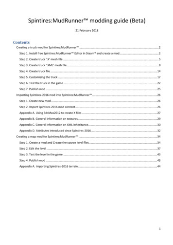
Figure 4: Mesh with Hexa27 and Hexa8The rest of the step involves selecting a solver, defining sideset IDs for boundary conditions, and writingan input file.Output - Select Solver - EXODUS-IIOutput - Part Boundary Conditions as in Figure 5Output - Write Input (Name the .exo file to be created)Figure 5: Boundary conditions (Sideset ID )CUBIT/TRELISIn this step, the Exodus mesh file created with ICEM-CFD will be imported to CUBIT and in order toidentify sideset IDs with their corresponding surfaces.
Figure 6: Cubit MeshCommands for example case import mesh geometry "C:\Users\YOURUSERNAME\Desktop\exodus.exo" block 2 usenodeset sideset linear no merge sideset 1 surface 1 sideset 2 surface 2 sideset 3 surface 3 sideset 4 surface 4 sideset 5 surface 5 export mesh "exporta.exo"At this step all boundaries can be confirmed and identified visually by clicking on sideset’s as shown inFigure 6MOABThis is the last step before the file can be read by Nek to create a mesh file with boundary conditions. mbconvert export a.exo tjunca.h5m //conversion mbpart 64 tjunca.h5m tjuncb.h5m // partioningNEK5000In this step, the partitioned file from MOAB will be read by NEK5000, and a mesh file will be created.
For this case, the MOAB example in the NEK5000/Example folder can be used by modifying parametersin the box area of Figure.Usr file also needs following lines as given below call gen rea(2) call exitt()Once run is done newrea.out file will be created with boundary conditions.Figure 7: Modifications to Nek5000 MOAB example scriptAcknowledgementThis work was made possible with the help from Dr. Elia Merzari, and Dr. Yiqi Yu from Argonne’s NEdivision.
converted to Hexa27 in ICEM CFD's Edit Mesh tab as shown in Figure 3. Edit mesh - Convert Mesh - Figure 3: Hexa8 to Hexa27 Step 3 Due to a problem with importing the mesh into Cubit/Trelis importing problem, there should be at least one Hexa8 element in the mesh. To create a trivial Hexa8 element, the following steps can be followed: