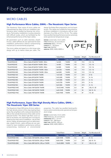
Transcription
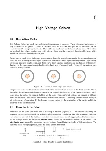
5.0High Voltage Cables High Voltage CablesHigh Voltage Cables are used when underground transmission is required. These cables are laid in ducts ormay be buried in the ground. Unlike in overhead lines, air does not form part of the insulation, and theconductor must be completely insulated. Thus cables are much more costly than overhead lines. Also, unlikefor overhead lines where tappings can easily given, cables must be connected through cable boxes whichprovide the necessary insulation for the joint.Cables have a much lower inductance than overhead lines due to the lower spacing between conductor andearth, but have a correspondingly higher capacitance, and hence a much higher charging current. High voltagecables are generally single cored, and hence have their separate insulation and mechanical protection bysheaths. In the older paper insulated cables, the sheath was of extruded lead. Figure 5.1 shows three suchcables, as usually laid out.Figure 5.1 - Layout of three, single-core cablesThe presence of the sheath introduces certain difficulties as currents are induced in the sheath as well. This isdue to fact that the sheaths of the conductors cross the magnetic fields set up by the conductor currents. At allpoints along the cable, the magnetic field is not the same, Hence different voltages are induced at differentpoints on the sheath. This causes eddy currents to flow in the sheaths. These eddy currents depend mainly on(a) the frequency of operation, (b) the distance between cables, (c) the mean radius of the sheath, and (d) theresistivity of the sheath material.5.1Power loss in the CablePower loss in the cable can occur due to a variety of reasons (Figure 5.2). They may be caused by theconductor current passing through the resistance of the conductor - conductor loss (also sometimes called thecopper loss on account of the fact that conductors were mainly made out of copper), dielectric losses causedby the voltage across the insulation, sheath losses caused by the induced currents in the sheath, andintersheath losses caused by circulating currents in loops formed between sheaths of different phases. Thedielectric loss is voltage dependant, while the rest is current dependant.HFFFFFFFI HFI{FFFFFFFFFM LFFFFFFFM LFFFFFFF¾ Heat generatedLFNFNFNFM JNK conductor lossdielectric sheath & intersheathlosslosslossFigure 5.2 - Heat Transfer in a cable due to losses
High Voltage Cables 5.1.1 Dielectric lossFor a perfect dielectric, the power factor is zero. Since the cable is not a perfect dielectric, the power factor isonot zero. The current leads the voltage by an angle of less than 90 , and hence there is a power loss (Figure5.3).If C is the capacitance of the cable, and E is the applied voltage, thencharging currentpower lossi EC&P E I cos 3 ( , VLQ / E (i/cos / VLQ / (2 C & WDQ /G ,G G G G /G 3JFFFFFFFFFFFFFFFFFFF¾EThe power loss is proportional to E and tan / 2Figure 5.3 - Loss angle5.1.2 Conductor lossThe conductor loss Pc is given by2Pc I Rcwattwhere Rc is the resistance of the conductor and I is the current in the cable.5.1.3 Sheath lossThe losses occurring in the sheath of a cable is usually obtained by the empirical formula of Arnold. Arnold'sformula for the sheath loss Psh is given by22 rm -3 I 7.7x P sh10R sh d where rmdRshI wattmean radius of sheathdistance between cables (centre to centre)resistance of full length of cablecurrent in cableThe sheath loss is usually about 2 to 5 % of the conductor loss.5.1.4 Intersheath LossIntersheath losses are caused by the induced emf between the sheaths causing a circulating current.This loss is thus present only when the sheaths of adjacent cables are connected together. The sheaths need tobe connected together in practice, as otherwise sparking could occur causing damage to the sheaths. Theintersheath loss Pish can be calculated as follows.The mutual inductance Msh between a core of one cable and the sheath of an adjacent cable is given byM sh µ d ln 2π r The voltage induced Eish is given byEish I . & 0sh
High Voltage Engineering - J R Lucas, 2001and the induced current Iish is given byI ish [RE ish2sh ω 2 M sh2] [R12i ω M sh 2sh ω 2 M sh2]12Therefore the intersheath loss Pish is given by2P ish I ish R sh 2I ω M sh .R sh22Rsh ω M sh22Generally, the sheath resistance Rsh & 0sh so thatI ω M shP ish R sh222The intersheath loss is larger than the sheath loss and may range from 10% to 50% of the copper loss. Thusthe total power loss (exclusive of the dielectric loss) is given asTotal Power loss Pc Psh Pish27.7 x 10-3 r m I 2 ω 2 M sh P loss I R IR sh d R sh222Since the whole expression is dependant on I2, we may express the loss in terms of an effective resistance Reff.This gives the total power loss in terms of the effective resistance as2Ptotal I Reff27.7 x 10 -3 r m ω 2 M sh R eff Rc R sh d Rsh2Since the sheath loss is usually very small, the effective conductor resistance can be written asω M shR eff Rc R sh225.1.5 Cross-bonding of CablesWhen three single phase cables are used in power transmission, currents are induced in the sheaths and lead tosheath circulating currents and power loss. These may be substantially reduced, and the current rating of thecable increased by cross bonding of the cables (Figure 5.4). Cross bonding of cables are done except for veryshort lengths of FFFFFFK Figure 5.4 - Cross bonding of sheaths
High Voltage Cables The continuity of each cable sheath is broken at regular intervals; the cables between two adjacentdiscontinuities being a minor section. 3 minor sections make up a major section, where the sheaths are solidlybonded together and to earth. A residual sheath voltage exists, and the desired balance, giving negligiblesheath voltage between the solid grounded positions is achieved by transposing the cables at each crossbonded section. To prevent excessive voltage build up at the cross bonded points, especially during faults,these points are earthed through non-linear resistors which limit voltage build up.The cable is alsotransposed. (Figure OFFOFFOFFFFFFigure 5.5 - Non-linear resistor earthing 5.2Impregnated Paper InsulationThe insulation consists mainly of paper tape impregnated with compound. The paper must be free fromligneous fibres and from metallic or other conducting spots. The compound with which the paper is insulatedshould be of such a consistency that it is plastic at ordinary temperatures, and has no tendency to drain awayfrom the cable.The impregnating compound varies from manufacturer to manufacturer,but they all are based o paraffinic ornaphthenic mineral oil, with resin frequently added to lower the viscosity and to improve its impregnatingqualities. The paper is made from Manila fibre or wood pulp.Impregnated paper can withstand an electric stress if about 5 to 10 times that which could be withstood by drypaper insulation. The dielectric strength of impregnated paper is about 200 to 300 kV/cm. Initially, they maybe able to withstand about 400 to 600 kV/cm. The cause of breakdown is usually the non-homogeneity of thedielectric. When a test voltage is applied, the weakest part of the dielectric breakdown and deterioration startsgetting more and more. This is accentuated by the fact that the cable is not carrying the same current all thetime. The deterioration results in the formation of voids and gasses. When the voltage is raised, ionisation orglow discharge can occur in the voids and ionic bombardment of thee surface. Some of the oil sufferscondensation and hydrogen and other gases are evolved. Thus the long term breakdown strength and theinstantaneous break down strengths differ. This value may decrease with time due to deterioration to about160 to 200 kV/cm. In the case of a badly impregnated dielectric, the breakdown stress will continue todecrease and ultimately leads to breakdown. With the use of a safety factor, not more than about 40 kV/cm isallowed in service (Figure 5.6).
High Voltage Engineering - J R Lucas, 2001b.d.v.¿500 MG400 M F F F F F F F F F F F F F F F F F F under pressure(15 atmospheres)G 300 M G 200 M F F F F F F F F F F F F F F F F F F without pressureG100 MG¾0 OFFFFFFFFFFFFFFFFFFFFFFFFFFFFFFFFFFFFFFFFFFFFtime (hrs)Figure 5.6 - Breakdown voltage characteristic of paper insulation5.2.1 Properties required of cable insulationDielectrics used for cable insulation must have the following properties.1.2.3.4.5.6.High Insulation resistanceHigh dielectric strengthGood mechanical strengthoImmune to attack by acids and alkali in the range 0 - 100 CShould not be too costlyShould not be hygroscopic (tending to absorb water), or if hygroscopic should be enclosed in awater tight covering.5.2.2 Principle underlying the design of high voltage cable insulation By means of dielectric tests on cables, it has been observed that the long term breakdown stress is increased ifthe cable is subjected to pressure. This is due to the fact that the pressure discourages the formation of voids.Even for a badly impregnated cable, the application of pressure improves the power factor (or loss tangent)considerably. If the cable is subjected to a pressure of about 15 atmospheres, the long term dielectric strengthimproves to about 400 kV/cm and a working stress of about 150 kV/cm may be used (Figure 5.7).¿¿breakdownMGstress GGGGG400 MGGG(kV/cm) G(a)G(b)GGGG300 M(b)GGGGGGG(a)200 M(c)GGGG(c)GGGG0.01 M100 MGGGGApplied FFFFFFFFFFOFFFFFF¾020406080 100 kV/cm100 (hrs)tan / ( 1 atmos) (a) impregnated(b) badly impregnated ( 1 atmos)(c) badly impregnated (15 atmos)Figure 5.7 - Variations with pressure (a) 15 atmospheres(b) 8 atmospheres(c) 1 atmosphere
High Voltage Cables Comparison of the curves for (a) well impregnated cable at atmospheric pressure, (b) badly impregnated cableat atmospheric pressure, and (c) badly impregnated cable at a pressure of 15 atmospheres for about 47 hours,shows the advantages of the pressure on the reduction of power factor. Further the curves show how the longterm breakdown stress is improved by pressure.In modern high voltage cables, with the use of better materials, the power factor has been reduced from about(0.007 to 0.01) to about (0.002 to 0.003).For high voltage cables, impregnated paper insulation is very commonly used. The paper is porous andcontains in itself the impregnating compound. There are no voids present as the oil is present between thelayers of the paper which forms the insulation.5.2.3 Paper insulated power cablesThe conductor of the cable is stranded, and this is lapped round with the paper tape. It is first heated to aboutoC100 taking care not to burn it. A vacuum is then applied for 20 to 50 hours to get rid of any trapped airinside the cable, and while still under vacuum, impregnating compound is poured into the tank and thereafter a2pressure of 50 p.s.i. (about 0.35 MN/m ) is applied. Impregnating of the paper prevents void formation in thedielectric, as voids can easily lead to the breakdown of the dielectric. As paper is hygroscopic, a seamlesslead sheath is extruded over the insulation so that no moisture will get in.For high voltages, pressurised cables are used where the impregnated paper insulation is kept under pressure.A pressure of about 15 atmospheres is applied so that any potential voids would be instantaneously filled.The pressure may be applied by having either oil or gas under pressure. When the cable is pressurised,longitudinal reinforcement to prevent bulging and reinforcement to prevent hoop stress are used. Withpressurised cables, the long term breakdown strength does not differ much from the short term strength, and assuch using a safety factor, a working stress of about 100 to 120 kV/cm may be used.5.2.4 Insulation ResistanceFor a single core cable (figure 5.8), the insulation resistance between the conductor and the outer sheath isgiven by the following. Res Rxû[rρ . x2π x lwhere l length of cable (m)Rρρdx ln( ) Res Res 2π l r x 2 π lrR3.665Rρ log10 ( ) x 10-10 M Ωl′rwhere l′ length of cable (km)i . e . Res Figure 5.8 - Cable cross-section
High Voltage Engineering - J R Lucas, 20015.2.5Capacitance in a single-core cableRConsider a single core cable (figure 5.9) with the following data.r radius of core (m)R radius of earthed sheath (m)q charge/unit length of cable (C/m)2D electric flux density charge density (C/m )00 permittivity of free space9 1/(4 [ [ ) F/mû[xrConsider an elemental cylinder of radius x and thickness dx, andof length unity along the cable.q D x 2 π x x1 , electric stress ξ also, ξ dv,dxi .e . V qFigure 5.9 - Cable cross-section2π xDq18 x 109 xq ε 2π ε0 ε r xεr xRRrrso that V ξ dx 18 x 109 xqdxεr x18 x 109qq log e (R/r ) log e (R/r )2π εεr capacitnace C D qεr F/m9V 18 x 10 log e (R/r )0.0383 ε r0.024 ε rµ F/mile µ F/kmlog10 (R/r)log10 (R/r)(For impregnated paper insulation, 0r 3.5)5.2.6 Three-core CablesWhen three phase power is being transmitted, either three single-core cables or a single three-core cable maybe used. In the case of the single core cables, the stress is radial, and its magnitude alternates with time. 01.0/ 0V1V2V312F F F F F F F F F F F3GGG12.3 1.0 - 0.5 - 0.5
High Voltage Cables1.0/300G1G1 0.866 0 - 0.866V1V2V3 0.966 - 0.259 - 0.707.3GG1.0/1501GG2GF F F F F F F F F F F2G3V1V2V32GF F F F F F F F F F F2G3 1.3GGFigure 5.10 - Equipotential lines in three-core cablesIn the case of the 3-core cable, since the centres of the cores lie in a circle, the electrostatic field is asomewhat rotating field and not a pulsating one. Typical variations of the equipotential surfaces, for a fewpoints of the cycle are illustrated in figure 5.10.From these it will be seen that the field lines, which are perpendicular to the equipotential lines, are not radialto the individual cores. Consequently, the electric stress is not radial, and tangential components of stressexist. If paper insulation is used around each cores, then tangential stresses will be applied along the surfaceof the paper rather than just across it. The electrical properties of paper varies in different directions. Theeffective dielectric stress of paper insulation is much greater across the layers than along it. Thus the presenceof tangential stress in paper insulation leads to greater risk of breakdown.5.2.7 Three-core belted type CablesIn the case of a 3-core cable, the 3-cores are individually insulated with paper insulation. The filler spacesbetween the core insulation is also filled up with insulation, but depriving these of voids is much moredifficult. Belt insulation is used on top of all three core insulations, and the lead sheath is extruded over this.Over the lead sheath, there is generally bitumen to prevent damage.In buried cables, additional protection is necessary to prevent damage. There are two types of armouring usedfor these cables.(i)Steel tape armouring-(ii)Steel wire armouring-the steel tape is usually wound in two layers with oppositedirections of laythe steel wires are laid in one or two layers.
High Voltage Engineering - J R Lucas, 2001Capacitance of 3-core belted typeThe capacitance between the conductor to neutral of 3-core beltedcables (Figure 5.11) cannot be obtained by a simple derivation asfor the single core cable. Simon's expression can be used toobtain this value.conductorThe capacitance per unit length to neutral is given byIftTd0r thickness of belt insulation thickness of conductor insulation diameter of conductor dielectric constantSheathFigure 5.11 - 3 core belted cableC0 0.03 ε r t t log 10 0.52 - 1.7 3.84 T T 2 T t 1 d µ F/kmMeasurement of capacitance of 3-core cablesIn three-core cables, capacitance does not have a single value, but can belumped as shown in figure 5.12.CsCCCsCsCapacitance between each core and sheath CsCapacitance between cores CThese can be separated from measurements as described in the followingsection. Cs Figure 5.12 - Cable Capacitances (a) Strap the 3 cores together and measure the capacitance between this bundle and the sheath as shown in figure CsCs5.13.CMeasured value-----------I G HFFFFFFFFI G---M %ULGJH L-KJFFFFFFFFK Cm1 3 CsThis gives the capacitance to the sheath as Cs Cm1/3(b) Connect 2 of the cores to the sheath and measurebetween the remaining core and the sheath (Figure 5.14).Figure 5.13 - Capacitance measurementMeasured value Cm2 2 C CsCCi.e. C (Cm2 - Cs)/2 (3 Cm2 - Cm1)/6which gives the capacitance between the conductors.CsCF F F F F FIHFFFFFFFFI GFM %ULGJH L F KJFFFFFFFFKFigure 5.14 - Capacitance measurement
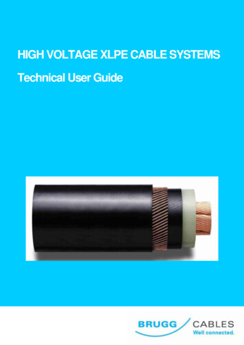
High Voltage Cables CsThe effective capacitance to neutral Co of any of the cores may be obtainedby considering the star equivalent (Figure 5.15). This gives3C13 C m 2 - Cm 1C0 C s 3 C C m 1 3363CCsCs3CC0 31Cm 2 - C m 126Figure 5.15 - Calculation of CoIn the breakdown of actual 3-core belted cables, it is generally observed that charring occurs at those placeswhere the stress is tangential to the layers of paper. Thus for the insulation to be effective, the tangentialstresses in paper insulation should be preferably avoided. This can usually be accomplished only screeningeach core separately (or by having individual lead sheaths for each of the cores), so that the cable in effectbecomes 3 individual cables laid within the same protective covering.5.2.8 Hochstadter or "H" type CableIn this type of cable (Figure 5.16), there is no belt insulation. The screening of individual cores is generallythin and flexible so that there is not much power dissipation in them. All the individual screens are earthed sothat the potential at these sheaths are all zero and thus the stress lines between the cores and screens would benow opper wovenfabriclead sheathconductorFigure 5.16 - H-type cableThe screens are thin so that there is hardly any current induced. The sheaths surrounding the insulation of thecores consist of metallised perforated paper. These are wrapped round with copper woven fabric (cotton tapeinto which are woven copper wire). This outer screen is in contact with the inner screens and is earthed. Thecable has the additional advantage that the separation of the cores by thermal expansion or mechanicaldisplacement cannot introduce stresses in the dielectric. The metallised screens help to dissipate the heat.These are used upto 66 kV. In the H-type cable, the individual cores contain no lead covering. The threecores are laid up with fillers in the ordinary way. If the cable is to be buried, then the cable is armoured withsteel wire and tape. The wormings of the H-type cable are full of oil.5.2.9 S.L. type CableAnother development of the screening principle is the SL type cable (Figure 5.17). In this, each core isscreened and then individually sheathed with lead or aluminium. These do not have an overall lead sheath.
High Voltage Engineering - J R Lucas, 2001coreinsulationcompoundjute wormingcottontapelead sheathcoreFigure 5.17 - S L type cableThe electric field in the insulation surrounding each core is naturally radial and the function of the screens inthis case is to eliminate the possibility of any stress across the clearance space between core and sheath. Thewormings of the filler spaces in the S.L. type cables do not contain much oil as do not get any electric stress.The three metal sheathed cores, after being lapped with paper and cotton tapes are laid with tarred jute yarn toget a circular formation and then wrapped with hessian tapes to form a bedding for the armouring. Theelectrical and thermal advantages of H-type cables are also enjoyed by the S.L. type cables. These cables aresuitable for hilly routes, as the absence of oil in the filler spaces lessens the risk of oil drainage. Also, the S.L.type construction is useful on short runs because the terminating equipment is simplified. Also the voidformation in the filler spaces are of no consequence. The separate lead sheaths in the S.L. cable are the seatsof induced currents, but the resulting losses are small, and appear to be of no practical significance.5.2.10 Copper Space FactorUnlike in overhead lines, insulation in cables occupies a greater portion of the cable space. Thus higherinstallation costs are involved. Ideally we would like the insulation to occupy the minimum possiblethickness. Thus we define a space factor to indicate the utilisation of the space. The copper space factor isdefined ascopper space factor cross-section area of conductorcross-section area of whole cableFor a single core cable, the best space factor is obtained with a concentricarrangement (Figure 5.18), as this gives the minimum conductor perimeter for thegreatest conductor area and given insulation thickness. Thus2Rr2Space factor r /RFigure 5.18For the 3-core cable (Figure 5.19), consisting of circular conductors withina circular sheath,22Space factor 3 r /Rwhere T thickness of core insulation, t thickness of belt insulationrtRTand R1 r THowever, for the 3-core cable the circular cross-section is not the best Figure 5.19 - three-core cableshape for the conductors.
High Voltage Cables Other shapes which gives better space factors are the elliptical shaped conductors and the sector shapedconductors (Figure 5.20).Figure 5.20 - Special shapes of conductors to give better space factors5.3Dielectric Stress in a Single Core CableThe voltage difference across the conductor and the sheath of a single core cable is given byv qRlog e ,2π εralso, ξ x q2π ε xvso that ξ x x log eRrIt is seen that since x is the only variable, the maximum stress in the dielectric occurs at the minimum value ofthe radius x (i.e. x r).i . e . ξ max Vr log eRrSince it is required that this maximum stress in the dielectric should be as low as possible, differentiating withrespect to r for minimum max givesd ξ max 0dr Vi .e . r log e R/r i. e.2 R 1 . log e r . - 0r r R e 2.718rThus if the overall diameter of the cable is kept fixed, then R/r e is the condition for minimum max. Thisvalue of radius of conductor will generally be larger than would be required for current carrying capacity.
High Voltage Engineering - J R Lucas, 2001Since R/r e, the minimum value of max is given byξ max VV r log e R/r rSince the radius of the conductor that would be given from the aboveexpression is larger than is necessary for current carrying capacity, thisvalue of radius may be achieved by using Aluminium or hollowconductors.ξξmAs can be seen (Figure 5.21), the dielectric is not equally stressed at allradii, in a cable of homogeneous insulation. The insulation is fully stressedonly at the conductor, and further away near the sheath the insulation isunnecessarily strong and thus needlessly expensive.05.3.1 Cable Grading for Uniform Stress DistributionrR xFigure 5.21 - Stress DistributionThe electric stress in the dielectric may be more equally distributed by one of the two following methods.(i) Capacitance grading(ii) Intersheath grading5.3.2 Capacitance GradingIn this method of grading, the insulation material consists ofvarious layers having different permittivities.Consider a cable graded by means of 3 layers of insulation, asshown in Figure 5.22, having permittivities 01, 02, 03, respectively.Let the outer radii of these layers by r1, r2 and r3 Rrespectively, an the conductor radius r.In order to secure the same value of maximum stress in each layer,the maximum stresses in the layers are equated.Let the voltage across the inner-most layer of insulation be V1.Thenq2π ε0 ε1 r q2 π ε 0 ε 2 r1 q2 π ε 0 ε 3 r2 ε 1 r ε 2 r1 ε 3 r2r1V 1 ξ max r log ersimilarlyV2 , V3 can be determinedm2ξm1 ξ ξm3ξ0rr1r2 R xFigure 5.22 - Capacitance Grading
High Voltage CablesTherefore the total voltage across the dielectric can be obtained as follows. V ξ max r ln r 1 r 1 ln r 2 r 2 ln r 3 rr1r2 RR ξ max r ln r1 r ln r 2 r ln ( r1 - r) ln r 2 ( r 2 - r) ln rr1r2r1r2 RR ξ max r ln ( r1 - r) ln r 2 ( r 2 - r) ln rr1r2 R ξ max r log e , since r1 r, r 2 rrHence by grading the insulation, without increasing the overall diameter of the cable, the operating voltage canbe raised. A difficulty with this method is that we cannot obtain a wide range of permittivities in practice, aspaper insulation has permittivities limited to the range 2.8 to 4.0.In the above analysis, it has been assumed that the maximum permissible stress is the same for all threedielectrics used. If the maximum stress in the three sections are different, and are 1, 2, 3 respectively, thenthe maximum stresses should be reached at the same time for the most economical operation of the insulation.This condition gives us the resultξ 1 ε 1 r ξ 2 ε 2 r1 ξ 3 ε 3 r 25.3.3 Intersheath GradingIn this method of grading, the same insulating material is usedthroughout the cable, but is divided into two or more layers bymeans of cylindrical screens or intersheaths (Figure 5.23). Theseintersheaths are connected to tappings from the supply transformer,and the potentials are maintained at such values that each layer ofinsulation takes its proper share of the total voltage. Theintersheaths are relatively flimsy, and are meant to carry only thecharging current.VV1 rV3r1V2r2Since there is a definite potential difference between the inner andouter radii of each sheath, we can treat each section separately as asingle core cable.If V1, V2, V3, . are the potential differences across the sectionsof insulation, thenξ max V1r log e r 1r V2r log e r 2r1 .Since the cable insulation now consists of a number of capacitorsin series, formed by the respective intersheaths, all potentialdifferences V1, V2, V3, . are in phase. Thus, if V is the phase toneutral voltage, we can also writeV V1 V2 V3 . . . . . . . . VnRξξm0rr1r2 R xFigure 5.23 - Intersheath Grading
High Voltage Engineering - J R Lucas, 2001In the particular case that all the n layers have the same thickness d, and if r is the conductor radius,r1 r d; r2 r 2d; r3 r 3d; . rn r n dVV1V2 . r dr 2 dMr log e(r d) log err dnr mdwhere M (r (m - 1) d ) log er (m - 1) dm 1ξ max thThe voltage across the m section is given byV m V[r (m - 1) d ]log e r m dMr (m - 1) dHence substituting for the different values of m, we can obtain the voltage across the various layers that haveto be maintained to give equal maximum stress in each section.In practice, there is a considerable difficulty in arranging for many intersheaths, this difficulty being mainlyassociated with the provision of the different voltages for the intersheaths, and as a result it is usual to design acable of this type with only one intersheath.This simplifies the design calculations, and the expression for the maximum stress then given byVξ max r1 log eR r log e r1rr1 For the purpose of comparison with the ungraded cable, let us first take the optimally designed ungraded cable(i.e. with R/r e), and introduce an intersheath at a radius r1. Since R and r are both kept fixed, r1 is the onlyvariable, and the expression for stress must be differentiated with respect to r1 to obtain the condition for theminimum value of the maximum stress.i . e . - 1 log eR r1r 0r1R e, also log e e 1r r1 log e r1 1rrconsiderin g ξ max 0 r1This gives the solution r1 1.76 r.1 - Rso that r1 . r . 2R r1 Rr 1 log e r . . 0r1r1 r
High Voltage Cables ξ max VV er 1.76 r 1.33 r1.76 r log e r log e 1.76rr However, for the cable without intersheath, we havethe maximum applicable voltage by 33% .max V/r. Hence, the addition of the intersheath raisesNow let us consider the case of only the overall diameter of the cable R being fixed, and both r and r1 beingvariable. Then for minimum value of the maximum stress we have ξ max 0, r ξ max 0 r1R ri . e . log e r1 - 1 0, also - 1 log e 0rr1 r1R 11i . e . r e, - 1 log e 0rr1 e1RRThis gives log e 1 giving 1.881er1r1ξ max VVV R1e r log e r log e e e r 1 - r e rr1 e i . e . ξ max 5.4V2.718 rPressurised High Voltage CablesIn high voltage paper insulated cables, the application of pressure (about 13 atmospheres) increases themaximum allowable working stress (after applying a suitable safety factor) from about 50 kV/cm to about 150kV/cm.In super voltage cables, the void control is effected by pressurising
paper insulation. The dielectric strength of impregnated paper is about 200 to 300 kV/cm. Initially, they may be able to withstand about 400 to 600 kV/cm. The cause of breakdown is usually the non-homogeneity of the dielectric. When a test voltage is applied, the weakest part of the dielectric breakdown and deterioration starts getting more and .