Transcription
SPECIFICATIONSPEC. No. A-150 C-cD A T E : 2016 Oct.ToNon-Controlled CopyUpon the acceptance of this spec.previous spec. (C2014-0057) shallbe abolished.CUSTOMER’S PRODUCT NAMETDK'S PRODUCT NAMEMultilayer Ceramic Chip CapacitorsCGA Series/ Automotive gradeHigh Temperature ApplicationPlease return this specification to TDK representatives with your signature.If orders are placed without returned specification, please allow us to judge that specification isaccepted by your side.RECEIPT CONFIRMATIONDATE:YEARMONTHDAYTest conditions in this specification based on AEC-Q200 for automotive application.TDK CorporationSalesElectronic ComponentsSales & Marketing GroupAPPROVEDPerson in chargeEngineeringElectronic Components Business CompanyCeramic Capacitors Business GroupAPPROVEDCHECKEDPerson in charge
1. SCOPEThis specification is applicable to chip type multilayer ceramic capacitors with a priority over theother relevant specifications.Production places defined in this specification shall be TDK Corporation Japan,TDK(Suzhou)Co.,Ltd and TDK Components U.S.A. Inc.EXPLANATORY NOTE:This specification warrant the quality of the ceramic chip capacitor. The chips should be evaluatedor confirmed a state of mounted on your product.If the use of the chips go beyond the bounds of this specification, we can not afford to guarantee.2. CODE CONSTRUCTION(Example)Catalog Number(Web)Item DescriptionCGA(1)2(2)B(3)2(4)X8R(5)1 E(6)103(7)K(8)050(9)CGA(1)2(2)B(3)2(4)X8R(5)1 E(6)103(7)K(8)T (12)(13)(1) Series(2) Case size symbolB(10)SymbolSeriesCGAFor automotive applicationTerminal electrodeBLGWBTInternal electrodeCeramic dielectricSymbol2345Type(EIA style)CC0402CC0603CC0805CC1206Symbol689Type(EIA style)CC1210CC1812CC2220*As for dimensions of each product, please refer to detailed inforamtion on TDK web.(3) .002.302.502.803.20
(4) Voltage condition in the life test(Details are shown in table 1 No.16 at 8.PERFORMANCE.)ConditionSymbol1Rated Voltage2Rated Voltage x 23Rated Voltage x 1.54Rated Voltage x 1.2(5) Temperature Characteristics(Details are shown in table 1 No.6 and No.7 at 8.PERFORMANCE.)(6) Rated VoltageSymbolRated VoltageSymbolRated Voltage2JDC 630 V1HDC 50 V2WDC 450 V1EDC 25 V2EDC 250 V1CDC 16 V2ADC 100 VSymbolRatedCapacitance(7) Rated CapacitanceStated in three digits and in units of pico farads (pF).The first and Second digits identify the first and secondsignificant figures of the capacitance, the third digitidentifies the multiplier.R is designated for a decimal point.(8) Capacitance tolerance2R22.2pF1051,000,000pF( 1μF)SymbolToleranceC 0.25 pFD 0.5 pFJ 5%K 10 %M 20 %Capacitance10pF and underOver 10pF(9) Thickness code (Only catalog number)(10) Package code (Only catalog number)(11) Special code (Only catalog number)(12) Packaging (Only item description)(Bulk is not applicable for CGA2(CC0402) type.)(13) TDK internal code (Only item description)—2—SymbolPackagingBBulkTTaping
3. RATED CAPACITANCE AND TOLERANCE3.1 Standard combination of rated capacitance and ce tolerance10pF andunder1NP0212pF to10,000pFOver10,000pFC ( 0.25pF)1, 1.5, 2, 2.2, 3, 3.3, 4, 4.7, 5D ( 0.5pF)6, 6.8, 7, 8, 9, 10E – 12 seriesJ ( 5 %)E – 6 seriesK ( 10 %)M ( 20 %)X8RRated capacitanceE – 6 series3.2 Capacitance Step in E seriesCapacitance StepE seriesE- 6E-121.01.01.51.21.51.82.22.22.74. OPERATING TEMPERATURE RANGEMin. operatingMax. operatingT.C.TemperatureTemperatureNP0,X8R-55 C150 C3.33.34.73.94.75.66.86.88.2ReferenceTemperature25 C5. STORING CONDITION AND TERM5 to 40 C at 20 to 70%RH6 months Max.6. P.C. BOARDWhen mounting on an aluminum substrate, large case size such as CGA6(CC1210),CGA8(CC1812) and CGA9(CC2220) types are more likely to be affected by heat stress fromthe substrate.Please inquire separate specification for the large case sizes when mounted on the substrate.7. INDUSTRIAL WASTE DISPOSALDispose this product as industrial waste in accordance with the Industrial Waste Law.—3—
8. PERFORMANCEtable 1No.ItemPerformanceTest or inspection method1External AppearanceNo defects which may affectperformance.2Insulation ResistanceApply rated voltage for 60s.10,000MΩ or 500MΩ·μF min.(As for the capacitors of ratedAs for the capacitor of rated voltage 630V DC,voltage 16V DC and,10,000 MΩ orapply 500V DC.100MΩ·μF min.,) whichever smaller.3Voltage ProofWithstand test voltage withoutinsulation breakdown or otherdamage.Inspect with magnifying glass (3 )T.C.NP0X8RRatedvoltage(RV)Apply voltageRV 100V3 rated voltage100V RV 500V 1.5 rated voltage500V RV1.3 rated voltageRV 100V2.5 rated voltage100V RV 500V 1.5 rated voltage500V RV1.3 rated voltageAbove DC voltage shall be applied for 1s.Charge / discharge current shall notexceed 50mA.4CapacitanceWithin the specified tolerance.Q(NP0)Dissipation Factor(X8R)6TemperatureCharacteristicsof Capacitance(NP0)As for spec of each product, pleaserefer to detailed inforamtion on TDKweb.Temperature Coefficient0 30 (ppm/ C)Capacitance drift within 0.2% or 0.05pF, whichever 1MHz 10%and under0.5 - 5 Vrms.Over 1000pF 1kHz 10%X8R5MeasuringfrequencyT.C.All1kHz 10% 1.0 0.2VrmsFor information which product has whichmeasuring voltage, please contact with oursales representative.See No.4 in this table for measuringcondition.Temperature coefficient shall be calculatedbased on values at 25 C and 85 Ctemperature.Measuring temperature below 20 C shallbe -10 C and -25 C.
(continued)No.7ItemTemperatureCharacteristicsof Capacitance(X8R)PerformanceCapacitance ChangeNo voltage applied 15(%)8Robustness ofTerminationsNo sign of termination coming off,breakage of ceramic, or otherabnormal signs.Test or inspection methodCapacitance shall be measured by thesteps shown in the following table afterthermal equilibrium is obtained for eachstep. C be calculated ref. STEP3 readingStepTemperature( C)125 22-55 2325 24150 2Reflow solder the capacitors ona P.C. board shown in Appendix2 andapply a pushing force of 17.7N with10 1s.(2N is applied for CGA2(CC0402) type)Pushing forceP.C. boardCapacitor9BendingNo mechanical damage.Reflow solder the capacitors ona P.C. board shown in Appendix1and bend it for 2mm. (1mm is appliedfor 0.85mm thickness of X8R items.)2050FR23045245(Unit : mm)10SolderabilityNew solder to cover over 75% oftermination.25% may have pin holes or roughspots but not concentrated in onespot.Ceramic surface of A sectionsshall not be exposed due tomelting or shifting of terminationmaterial.A section—5—Completely soak both terminationsin solder at the following conditions.Solder : Sn-3.0Ag-0.5Cu or Sn-37PbTemperature : 245 5 C(Sn-3.0Ag-0.5Cu)235 5 C(Sn-37Pb)Soaking time : 3 0.3s(Sn-3.0Ag-0.5Cu)2 0.2s(Sn-37Pb)Flux: Isopropyl alcohol (JIS K 8839)Rosin (JIS K 5902) 25% solidsolution.
(continued)No.11ItemPerformanceResistance ExternalNo cracks are allowed andto solderappearance terminations shall be covered atheatleast 60% with new Change from thevalue before testNP0 2.5% or 0.25pF,whichever larger.X8R 7.5 %D.F.(X8R)Meet the initial spec.InsulationResistanceMeet the initial spec.VoltageproofNo insulation breakdown orother damage.ExternalappearanceNo mechanical damage.QPreheating conditionTemp.: 110 140 CTime : 30 60s.Solder : Sn-3.0Ag-0.5Cu or Sn-37PbLeave the capacitors in ambientcondition for 6 to 24h (NP0) or24 2h (X8R) before measurement.CharacteristicsChange from thevalue before testNP0 2.5% or 0.25pF,whichever larger.X8R 7.5 %Meet the initial spec.(NP0)D.F.(X8R)Completely soak both terminations insolder at the following conditions.260 5 C for 10 1s.Flux : Isopropyl alcohol (JIS K 8839)Rosin (JIS K 5902) 25% solidsolution.Meet the initial spec.CapacitanceTest or inspection methodMeet the initial spec.—6—Reflow solder the capacitors ona P.C. board shown in Appendix2before testing.Vibrate the capacitors with followingconditions.Applied force : 5G max.Frequency : 10-2,000HzDuration : 20 min.Cycle : 12 cycles in each 3 mutuallyperpendicular directions.
(continued)No.Item13Temperature ExternalappearancecyclePerformanceTest or inspection methodNo mechanical damage.CapacitanceCharacteristicsChange from thevalue before testNP0 2.5% or 0.25pF,whichever larger.X8R 7.5 %Reflow solder the capacitors ona P.C. board shown in Appendix2 beforetesting.Expose the capacitors in the conditionstep1 through step 4 and repeat 1,000times consecutively.Leave the capacitors in ambientcondition for 6 to 24h (NP0) or 24 2h(X8R) before measurement.StepQ1Meet the initial spec.(NP0)1423D.F.(X8R)Meet the initial spec.InsulationResistanceMeet the initial spec.VoltageproofNo insulation breakdown orother damage.4MoistureNo mechanical nceChange from theCharacteristicsState)value before testQ(NP0)D.F.(X8R)InsulationResistanceNP0 5% or 0.5pF,whichever larger.X8R 12.5 %CapacitanceQ30pF and over350 min.10pF and overunder 30pF275 5/2 C min.Under 10pF200 10 C min.C : Rated capacitance (pF)200% of initial spec. max.1,000MΩ or 50MΩ·μF min.(As for the capacitors of ratedvoltage 16V DC, 1,000 MΩ or10MΩ·μF min.,) whicheversmaller.—7—Temperature( C)-55 325150 225Time (min.)30 32-530 22-5Reflow solder the capacitors ona P.C. board shown in Appendix2before testing.Leave at temperature 40 2 C, 90 to95%RH for 500 24,0h.Leave the capacitors in ambientcondition for 6 to 24h (NP0) or24 2h (X8R) before measurement.
(continued)No.Item15MoistureExternalResistance appearancePerformanceNo mechanical damage.CapacitanceQ(NP0)D.F.(X8R)16LifeTest or inspection methodReflow solder the capacitors on a P.C.board shown in Appendix2 before testing.CharacteristicsChange from thevalue before testApply the rated voltage at temperature85 C and 85%RH for 1,000 48,0h.NP0 7.5% or 0.75pF,whichever larger.Charge/discharge current shall notX8R 12.5 %CapacitanceQ30pF and over200 and overUnder 30pF100 10/3 C min.C : Rated capacitance (pF)200% of initial spec. max.InsulationResistance500MΩ or 25MΩ·μF min.(As for the capacitors of ratedvoltage 16V DC, 500 MΩ or5MΩ·μF min.,) whichever smaller.ExternalappearanceNo mechanical damage.CapacitanceCharacteristicsNP0X8RChange from thevalue before test 3% or 0.3pF,whichever larger. 15 %exceed 50mA.Leave the capacitors in ambient conditionfor 6 to 24h (NP0) or 24 2h (X8R) beforemeasurement.Voltage conditioning (only for X8R)Voltage treat the capacitors under testingtemperature and voltage for 1 hour.Leave the capacitors in ambient conditionfor 24 2h before measurement.Use this measurement for initial value.Reflow solder the capacitors ona P.C. board shown in Appendix2 beforetesting.Below the voltage shall be applied at150 2 C for 1,000 48,0h.Applied VoltageRated voltage x2Q(NP0)CapacitanceQ30pF and over350 and over10pF and over to275 5/2 C min.under 30pFUnder 10pFD.F.(X8R)InsulationResistance200 10 C min.C : Rated capacitance (pF)200% of initial spec. max.1,000MΩ or 50MΩ·μF min.(As for the capacitors of ratedvoltage 16V DC,1,000 MΩ or10MΩ·μF min.,) whicheversmaller.Rated voltage x1.5Rated voltage x1.2Rated voltage x1As for applied voltage, please contactwith our sales representative.Charge/discharge current shall notexceed 50mA.Leave the capacitors in ambient conditionfor 6 to 24h (NP0) or 24 2h (X8R) beforemeasurement.Voltage conditioning (only for X8R)Voltage treat the capacitors under testingtemperature and voltage for 1 hour.Leave the capacitors in ambient conditionfor 24 2h before measurement.Use this measurement for initial value.*As for the initial measurement of capacitors (X8R) on number 7,11,12,13 and 14 leave capacitors at150 –10,0 C for 1 hour and measure the value after leaving capacitors for 24 2h in ambient condition.—8—
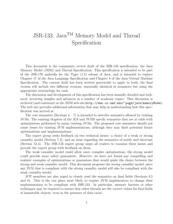
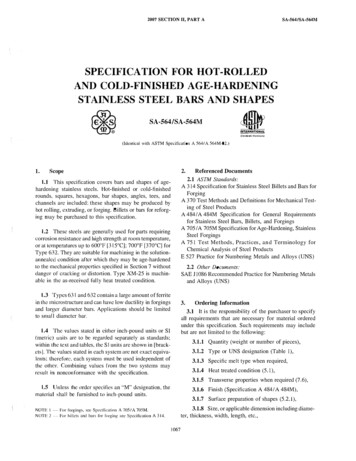
Appendix1P.C. board for bending 040c1.01.0aaSolder resistCoppercSolder resistCopperAppendix2P.C. Board for reliability test10040abcSlitSolder resistCopper(It is recommended to provide a slit on P.C. board for CGA6,CGA8 and CGA9.)(Unit:mm)TypeDimensionsTDK(EIA style)abcCGA2 (CC0402)0.41.50.5CGA3 (CC0603)1.03.01.2CGA4 (CC0805)1.24.01.65CGA5 (CC1206)2.25.02.0CGA6 (CC1210)2.25.02.9CGA8 (CC1812)3.57.03.7CGA9 (CC2220)4.58.05.61. Material : Glass Epoxy(As per JIS C6484 GE4)2. Thickness : Appendix 1 ― 0.8mm― 1.6mm: Appendix 2 ― 1.6mmCopper(Thickness:0.035mm)Solder resist(CGA2)(CGA3,CGA4,CGA5,CGA6,CGA8,CGA9)—9—
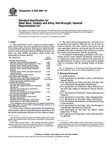
9. INSIDE STRUCTURE AND P0X8RCaZrO 3BaTiO 3Nickel (Ni)3Copper (Cu)4Nickel (Ni)Termination5Tin (Sn)10. PACKAGINGPackaging shall be done to protect the components from the damage during transportation and storing,and a label which has the following information shall be attached.1) Total number of components in a plastic bag for bulk packaging : 1000pcs2) Tape packaging is as per 14. TAPE PACKAGING SPECIFICATION.(CGA2 [CC0402] types are applicable only to tape packaging.)1)2)3)4)Inspection No.TDK P/NCustomer's P/NQuantity*Composition of Inspection No.ExampleF6A(a) (b) (c)a)b)c)d)e)–ΟΟ(d)–ΟΟΟ(e)Line codeLast digit of the yearMonth and A for January and B for February and so on. (Skip I)Inspection Date of the month.Serial No. of the day11. RECOMMENDATIONAs for CGA6 [CC1210] and larger, It is recommended to provide a slit (about 1mm width)in the board under the components to improve washing Flux. And please make sure to drydetergent up completely before.12. SOLDERING CONDITIONAs for CGA2 [CC0402], CGA6 [CC1210] and larger, reflow soldering only.— 10 —
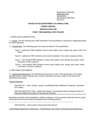
13. age,Transportation)1-1. Storage1) The capacitors must be stored in an ambient temperature of 5 to 40 C with arelative humidity of 20 to 70%RH. The products should be used within 6 monthsupon receipt.2) The capacitors must be operated and stored in an environment free of dewcondensation and these gases such as Hydrogen Sulphide, Hydrogen Sulphate,Chlorine, Ammonia and sulfur.3) Avoid storing in sun light and falling of dew.4) Do not use capacitors under high humidity and high and low atmospheric pressurewhich may affect capacitors reliability.5) Capacitors should be tested for the solderability when they are stored for long time.1-2. Handling in transportationIn case of the transportation of the capacitors, the performance of the capacitorsmay be deteriorated depending on the transportation condition.(Refer to JEITA RCR-2335C 9.2 Handling in transportation)2Circuit design Caution2-1. Operating temperatureOperating temperature should be followed strictly within this specification, especiallybe careful with maximum temperature.1) Do not use capacitors above the maximum allowable operating temperature.2) Surface temperature including self heating should be below maximum operatingtemperature.(Due to dielectric loss, capacitors will heat itself when AC is applied. Especially athigh frequencies around its SRF, the heat might be so extreme that it may damageitself or the product mounted on. Please design the circuit so that the maximumtemperature of the capacitors including the self heating to be below the maximumallowable operating temperature. Temperature rise at capacitor surface shall bebelow 20 C)3) The electrical characteristics of the capacitors will vary depending on thetemperature. The capacitors should be selected and designed in taking thetemperature into consideration.2-2. Operating voltage1) Operating voltage across the terminals should be below the rated voltage.When AC and DC are super imposed, V0-P must be below the rated voltage.— (1) and (2)AC or pulse with overshooting, VP-P must be below the rated voltage.— (3), (4) and (5)When the voltage is started to apply to the circuit or it is stopped applying, theirregular voltage may be generated for a transit period because of resonance orswitching. Be sure to use the capacitors within rated voltage containing theseIrregular voltage.Voltage(1) DC voltagePositionalMeasurement V0-P(Rated voltage)0(4) Pulse voltage (A) (5) Pulse voltage (B)PositionalMeasurement VP-P(Rated voltage)0VP-P— 12 —(3) AC voltageVP-PV0-P0Voltage(2) DC AC voltage00
No.ProcessCondition2Circuit design Caution2) Even below the rated voltage, if repetitive high frequency AC or pulse is applied, thereliability of the capacitors may be reduced.3) The effective capacitance will vary depending on applied DC and AC voltages.The capacitors should be selected and designed in taking the voltages intoconsideration.2-3. FrequencyWhen the capacitors (Class 2) are used in AC and/or pulse voltages, thecapacitors may vibrate themselves and generate audible sound.3DesigningP.C. boardThe amount of solder at the terminations has a direct effect on the reliability of thecapacitors.1) The greater the amount of solder, the higher the stress on the chip capacitors,and the more likely that it will break. When designing a P.C. board, determine theshape and size of the solder lands to have proper amount of solder on theterminations.2) Avoid using common solder land for multiple terminations and provide individualsolder land for each terminations.3) Size and recommended land dimensions.Chip capacitorsSolder landCBSolder resistAFlow 06)A0.7 - 1.01.0 - 1.32.1 - 2.5B0.8 - 1.01.0 - 1.21.1 - 1.3C0.6 - 0.80.8 - 1.11.0 - 1.3SymbolReflow 4(CC0805)A0.3 - 0.50.6 - 0.80.9 - 1.2B0.35 - 0.450.6 - 0.80.7 - 0.9C0.4 - 0.60.6 - 0.80.9 - )A2.0 - 2.42.0 - 2.43.1 - 3.74.1 - 4.8B1.0 - 1.21.0 - 1.21.2 - 1.41.2 - 1.4C1.1 - 1.61.9 - 2.52.4 - 3.24.0 - 5.0TypeSymbol— 13 —
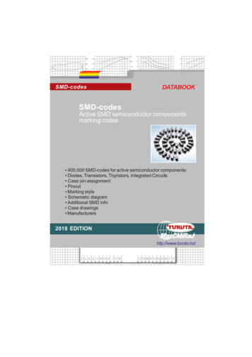
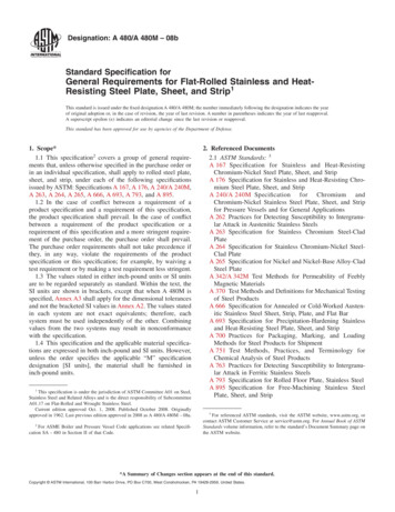
No.3ProcessDesigningP.C. boardCondition4) Recommended chip capacitors layout is as following.Disadvantage againstbending stressAdvantage againstbending stressPerforation or slitPerforation or slitMountingfaceBreak P.C. board withmounted side up.Mount perpendicularly toperforation or slitPerforation or slitBreak P.C. board withmounted side down.Mount in parallel withperforation or slitPerforation or slitChiparrangement(Direction)Closer to slit is higher stressAway from slit is less stressℓ2ℓ1Distance fromslit( ℓ1 ℓ2 )— 14 —( ℓ1 ℓ2 )
No.Process3DesigningP.C. boardCondition5) Mechanical stress varies according to location of chip capacitors on the P.C. board.EPerforationDCBASlitThe stress in capacitors is in the following order.A B C D E6) Layout recommendationExampleUse of commonsolder landSoldering withchassisLead wire ChassischipSolderUse of commonsolder land withother SMDSolderlandExcessive solderNeed toavoidExcessive solderPCB AdhesiveSolder landℓ1MissingsolderLead wireSolder landSolder resistSolder resistRecommendationSolder resistℓ2ℓ2 ℓ1— 15 —
4ProcessMountingCondition4-1. Stress from mounting headIf the mounting head is adjusted too low, it may induce excessive stress in the chipcapacitors to result in cracking. Please take following precautions.1) Adjust the bottom dead center of the mounting head to reach on the P.C. boardsurface and not press it.2) Adjust the mounting head pressure to be 1 to 3N of static weight.3) To minimize the impact energy from mounting head, it is important to providesupport from the bottom side of the P.C. board.See following examples.Not recommendedSingle sidedmountingRecommendedCrackSupport pinDouble-sidesmountingSolderpeelingCrackSupport pinWhen the centering jaw is worn out, it may give mechanical impact on the capacitorsto cause crack. Please control the close up dimension of the centering jaw andprovide sufficient preventive maintenance and replacement of it.4-2. Amount of adhesiveaaccbNo.Example : CGA4 (CC0805), CGA5 (CC1206)a0.2mm min.b70 - 100μmcDo not touch the solder land— 16 —
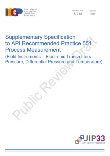
Soldering5-1. Flux selectionAlthough highly-activated flux gives better solderability, substances which increaseactivity may also degrade the insulation of the chip capacitors. To avoid suchdegradation, it is recommended following.1) It is recommended to use a mildly activated rosin flux (less than 0.1wt% chlorine).Strong flux is not recommended.2) Excessive flux must be avoided. Please provide proper amount of flux.3) When water-soluble flux is used, enough washing is necessary.5-2. Recommended soldering profile by various methodsReflow solderingWave solderingSolderingPreheatingPeakTempPeakTemp T0SolderingNatural coolingPreheatingNatural coolingTemp. ( C)5ConditionTemp. ( C)ProcessOver 60 sec.Over 60 sec. T0Over 60 sec.Peak Temp timePeak Temp timeManual soldering(Solder iron)APPLICATIONAs for CGA3 (CC0603), CGA4 (CC0805) andPeakTempCGA5 (CC1206), applied to wave solderingand reflow soldering.Temp. ( C)No.As for CGA2 (CC0402), CGA6 (CC1210), TCGA8 (CC1812) and CGA9 (CC2220),applied only to reflow soldering.Preheating03sec. (As short as possible)※ As for peak temperature of manual soldering, please refer“5-6. Solder repair by solder iron”.5-3. Recommended soldering peak temp and peak temp durationTemp./DurationWave solderingReflow solderingPeak temp( C) Duration(sec.)Peak temp( C)Duration(sec.)Sn-Pb Solder250 max.3 max.230 max.20 max.Lead Free Solder260 max.5 max.260 max.10 max.SolderRecommended solder compositionsSn-37Pb (Sn-Pb solder)Sn-3.0Ag-0.5Cu (Lead Free Solder)— 17 —
No.Process5SolderingCondition5-4. Avoiding thermal shock1) Preheating conditionSolderingTypeWave solderingReflow solderingManual soldering2)Temp. ( C)CGA3(CC0603), CGA4(CC0805),CGA5(CC1206)CGA2(CC0402), CGA3(CC0603),CGA4(CC0805), CGA5(CC1206)CGA6(CC1210), CGA8(CC1812),CGA9(CC2220)CGA2(CC0402), CGA3(CC0603),CGA4(CC0805), CGA5(CC1206)CGA6(CC1210), CGA8(CC1812),CGA9(CC2220) T 150 T 150 T 130 T 150 T 130Cooling conditionNatural cooling using air is recommended. If the chips are dipped into a solvent forcleaning, the temperature difference ( T) must be less than 100 C.5-5. Amount of solderExcessive solder will induce higher tensile force in chip capacitors whentemperature changes and it may result in chip cracking. In sufficient solder maydetach the capacitors from the P.C. board.Higher tensile force inchip capacitors to causecrackExcessivesolderMaximum amountMinimum amountAdequateLow robustness maycause contact failure orchip capacitors come offthe P.C. board.Insufficientsolder5-6. Solder repair by solder iron1) Selection of the soldering iron tipTip temperature of solder iron varies by its type, P.C. board material and solderland size. The higher the tip temperature, the quicker the operation. However,heat shock may cause a crack in the chip capacitors.Please make sure the tip temp. before soldering and keep the peak temp andtime in accordance with following recommended condition. (Please preheat thechip capacitors with the condition in 5-4 to avoid the thermal shock.)Recommended solder iron condition (Sn-Pb Solder and Lead Free Solder)TypeTemp. ( 350 max.CGA6(CC1210)CGA8(CC1812)CGA9(CC2220)280 max.— 18 —Duration (sec.)Wattage (W)Shape (mm)3 max.20 max.Ø 3.0 max.
No.Process5SolderingCondition2) Direct contact of the soldering iron with ceramic dielectric of chip capacitorsmay cause crack. Do not touch the ceramic dielectric and the terminations bysolder iron.5-7.Soldering rework using spot heaterHeat stress during rework may possibly be reduced by using a spot heater(also called a “blower”) rather than a soldering iron.It is applied only to adding solder in the case of insufficient solder amount.1) Reworking using a spot heater may suppress the occurrence of cracks in thecapacitor compared to using a soldering iron. A spot heater can heat up a capacitoruniformly with a small heat gradient which leads to lower thermalstress caused by quick heating and cooling or localized heating.Moreover, where ultra-small capacitors are mounted close together on a printedcircuit board, reworking with a spot heater can eliminate the risk of direct contactbetween the tip of a soldering iron and a capacitor.2) Rework conditionIf the blower nozzle of a spot heater is too close to a capacitor, a crack in thecapacitor may occur due to heat stress. Below are recommendations for avoidingsuch an occurrence.Keep more than 5mm between a capacitor and a spot heater nozzle.The blower temperature of the spot heater shall be lower than 400 C.The airflow shall be set as weak as possible.The diameter of the nozzle is recommended to be 2mm(one-outlet type).The size isstandard and common.Duration of blowing hot air is recommended to be 10s or less for CGA3 (CC0603),CGA4 (CC0805) and CGA5 (CC1206), and 30s or less for CGA6 (CC1210),CGA8(CC1812) and CGA9 (CC2220), considering surface area of the capacitorand melting temperature of solder.The angle between the nozzle and the capacitor is recommended to be 45degreesin order to work easily and to avoid partial area heating.As is the case when using a soldering iron, preheating reduces thermal stress oncapacitors and improves operating efficiency.・Recommended rework condition(Consult the component manufactures for details.)Distance from nozzle5mm and overNozzle angle45degreesNozzle temp.400 C and lessSet as weak as possible(The airflow shall be the minimum value necessary forsolder to melt in the conditions mentioned above.)φ2mm(one-outlet type)AirflowNozzle diameterBlowing duration10s and less (CGA3 [CC0603], CGA4 [CC0805], CGA5 [CC1206])30s and less (CGA6 [CC1210], CGA8 [CC1812], CGA9 [CC2220])・Example of recommended spot heater useOne-outlet type nozzleAngle : 45degrees— 19 —
No.Process5SolderingCondition3) Amount of solder should be suitable to from a proper fillet shape.Excess solder causes mechanical and thermal stress on a capacitor andresults in cracks. Insufficient solder causes weak adherence of the capacitorto the substrate and may result in detachment of a capacitor and deterioratereliability of the printed wiring board.See the example of appropriate solder fillet shape for 5-5.Amount of solder.5-8. Sn-Zn solderSn-Zn solder affects product reliability.Please contact TDK in advance when utilize Sn-Zn solder.5-9. Countermeasure for tombstoneThe misalignment between the mounted positions of the capacitors and the landpatterns should be minimized. The tombstone phenomenon may occur especiallythe capacitors are mounted (in longitudinal direction) in the same direction of thereflow soldering.(Refer to JEITA RCR-2335C Annex A (Informative) Recommendations to prevent thetombstone phenomenon)6Cleaning1) If an unsuitable cleaning fluid is used, flux residue or some foreign articles maystick to chip capacitors surface to deteriorate especially the insulation resistance.2) If cleaning condition is not suitable, it may damage the chip capacitors.2)-1. Insufficient washing(1) Terminal electrodes may corrode by Halogen in the flux.(2) Halogen in the flux may adhere on the surface of capacitors, and lower theinsulation resistance.(3) Water soluble flux has higher tendency to have above mentionedproblems (1) and (2).2)-2. Excessive washingWhen ultrasonic cleaning is used, excessively high ultrasonic energy outputcan affect the connection between the ceramic chip capacitor's body and theterminal electrode. To avoid this, following is the recommended condition.Power : 20 W/ max.Frequency : 40 kHz max.Washing time : 5 minutes max.2)-3. If the cleaning fluid is contaminated, density of Halogen increases, and it maybring the same result as insufficient cleaning.— 20 —
No.7ProcessCoating andmolding of theP.C. boardCondition1) When the P.C. board is coated, please verify the quality influence on the product.2) Please verify carefully that there is no harmful decomposing or reaction gasemission during curing which may damage the chip capacitors.3) Please verify the curing temperature.8Handling afterchip mounted Caution1) Please pay attention not to bend or distort the P.C. board after solderingin handling otherwise the chip capacitors may crack.BendTwist2) Printed circuit board cropping should not be carried out by hand, but by using theproper tooling. Printed circuit board cropping should be carried out using a boardcropping jig as shown in the following figure or a board cropping apparatus toprevent inducing mechanical stress on the board.(1)Example of a board cropping jigRecommended example: The board should be pushed from the back side,close to the cropping jig so that the board is not bent and the stress applied tothe capacitor is compressive.Unrecommended example: If the pushing point is far from the cropping jig andthe pushing direction is from the front side of the board, large tensile stress isapplied to the capacitor, which may cause cracks.Outline of rcuitboardDirection ofloadComponentsLoad pointSlotBoardcropping jigV-groove— 21 —SlotUnrecommendedDirectionof loadLoad pointPrintedcircuitboardComponentsV-grooveSlot
No.8ProcessHandling afterchip mounted CautionCondition(2)Example of a board cropping machineAn outline of a printed circuit board cropping machine is shown below. Thetop and bottom blades are aligned with one another along the lines with theV-grooves on printed circuit board when cropping the board.Unrecommended example: Misalignment of blade position between top andbottom, right and left, or front and rear blades may cause a crack in thecapacitor.Outline of machinePrinciple of operationTopbladeTop bladePrinted circuit boardPrinted circuit boardBottom bladeV-grooveCross-section diagramTop bladePrinted circuit boardBottom entTop bladeTop bladeTop bladeBottom bladeBottom bladeBottom bladeTop bladeBoardBottom blade3) When functional check of the P.C. board is performed, check pin pressure tendsto be adjusted higher for fear of loose contact. But if the pressure is excessiveand bend the P.C. board, it may crack the chip capa
Apply rated voltage for 60s. As for the capacitor of rated voltage 630V DC, apply 500V DC. 3 Voltage Proof Withstand test voltage without insulation breakdown or other damage. T.C. Rated voltage(RV) Apply voltage NP0 RV 100V 3 rated voltage 100V RV 500V 1.5 rated voltage 500V RV 1.3 rated voltage X8R RV 100V 2.5 rated voltage