Transcription
HIGH VOLTAGE XLPE CABLE SYSTEMSTechnical User Guide
High Voltage XLPE Cable SystemsTechincal User GuideContent1. General information on High Voltage XLPE Cable Systems31.1. Introduction31.2. Cable selection process31.3. Service life42. Cable layout and system design62.1. Electrical field62.2. Capacity, charging current62.3. Inductance, Inductive reactance72.4. Losses in cables72.5. Earthing methods, induced voltage82.6. Short-circuit current capacity 102.7. Dynamic forces 112.8. Metallic sheath types 113. XLPE Cable System Standards 134. Technical data sheets 14500 / 290 kV XLPE Cable400 / 230 kV XLPE Cable345 / 200 kV XLPE Cable220 / 127 kV XLPE Cable132 / 76 kV XLPE Cable5. XLPE Cable Reference Projects from Brugg 20Brugg CablesPage 2
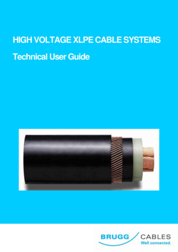
High Voltage XLPE Cable SystemsTechincal User Guide1. General information on High VoltageCable Systems1.1 IntroductionThe development of high voltage XLPE CableSystems goes back to the 1960’s. Since thenproduction and material technology haveimproved significantly, providing reliable andmaintenance-free products to the utility industry.At present, numerous high voltage XLPE cablesystems with nominal voltages up to 500 kV andwith circuit lengths up to 40 km are in operationworldwide.Cable systems are equipped with accessories,which have passed the relevant type testspursuant to national and international standards,such as long-duration tests. As one of the firstXLPE cable manufacturers worldwide BruggCables passed a Prequalification Test on a400 kV XLPE Cable System according to therelevant international standard IEC 62067 (2001).This test required one year of operation, alongwith the thermal monitoring of all cables, jointsand terminations installed. It was successfullycompleted at CESI Laboratory in Milan, Italy in2004.Test Setup of Prequalification TestAs one of just a few providers worldwide, BruggCables can offer a broad range of both XLPEcables (up to 500 kV) and oil-filled cables (up to400 kV) as well as their accessories.Typical sample of a 2500mm2 500 kV XLPE cableModern XLPE cables consist of a solid cable core,a metallic sheath and a non-metallic outercovering. The cable core consists of theconductor, wrapped with semiconducting tapes,the inner semiconducting layer, the solid maininsulation and the outer semiconducting layer.These three insulation layers are extruded in oneprocess. The conductor of high voltage cables canbe made of copper or aluminium and is eitherround stranded of single wires or additionallysegmented in order to to reduce the currentlosses.Depending on the customer’s specifications it canbe equipped with a longitudinal water barriermade of hygroscopic tapes or powder. The maininsulation is cross-linked under high pressure andtemperature. The metallic sheath shall carry theshort-circuit current in case of failure. It can beoptionally equipped with fibers for temperaturemonitoring. Finally, the outer protection consists ofextruded Polyethylene (PE) or Polyvinylchloride(PVC) and serves as an anti-corrosion layer.Optionally it can be extruded with asemiconducting layer for an after-laying test andadditionally with a flame-retardant material forinstallation in tunnels or buildings if required.1.2 Cable selection processThis broad product range together with asystematic analysis of the technical requirementsenables the user to find the right solution for everyBrugg Cablesapplication. Additionally, our consulting engineerscan assist you in the development of customizedsolutions.Page 3
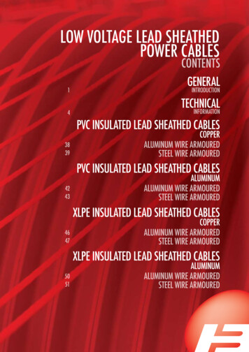
High Voltage XLPE Cable SystemsTechincal User GuideCustomerrequirementsLoad, Voltage level,Short-circuit current,Laying conditionType ofInsulationCable typeand designEconomicaspects(Price, Losses)ConductorMaterial (Cu, Al)Route lengthand layoutEarthing methodof sheathEconomicaspects,Safety marginConductorcross-sectionShort-circuit andthermal ratingIndoor or OutdoorSelection ofcable accessoriesLeakage n ofLaying conditionLocal boundaries,Safety regulationSelection process of cable design1.3 Service lifeCables are among the investment goods with ahigh service life of over 40 years. The service lifeof a cable is defined as its operating time. It isinfluenced by the applied materials, theconstructive design, the production methods andthe operating parameters.Regarding the material technology Brugg Cableshas many years of experience and investigationtogether with extensive experience in the field ofcable systems gained over the years.Lifetime curve of XLPE cablesBreakdown stress(kV/mm)504540353025201510501,0E 001,0E 011,0E 021,0E 031,0E 04Cable lifetime (hours)Lifetime curve of XLPE cablesBrugg CablesPage 4
High Voltage XLPE Cable SystemsThe following rules apply for all organic insulationmaterials in general:- An increase of the operating temperature by 8to 10 C reduces the service life by half.- An increase of the operating voltage by 8 to10% reduces the service life by half.The influence of the voltage on the service life isexpressed in the following service life law(see graph above):t En constTechincal User GuideOther operating parameters of decisiveimportance are:- Voltage level and transient voltages such asswitch operations, lightning impulses- Short-circuit current and related conductortemperatures- Mechanical stress- Ambient conditions like humidity, groundtemperatures, chemical influences- Rodents and termites in the vicinitywithE Maximum field strength at the conductorsurface of the cablen Exponent stating the slopet TimeBrugg CablesPage 5
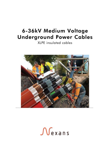
High Voltage XLPE Cable SystemsTechincal User Guide2. Cable layout and system designThe dimensioning of a high voltage cable systemis always based on the specifications anddemands of the project at hand. The followingdetails are required for calculation:- The type of cable insulation- Nominal and maximum operating voltage- Short-circuit capacity or short-circuit current withstatement of the effect time- Transmission capacity or nominal current- Operating mode: permanent operation or partialload operation (load factors)- Ambient conditions: Type of installation Ambient temperatures (incl. external effects) Special thermal resistance of the groundThe calculation of the admissible load currents(ampacity) and the cable temperatures isperformed in accordance with the IEC publication60287. At Brugg Cables, professional computerprograms are in use for the calculation of thevarious cable data.2.1 Electrical fieldIn initial approximation, the main insulation of ahigh voltage XLPE cable can be regarded as ahomogenous cylinder. Its field distribution orvoltage gradient is therefore represented by ahomogenoius radial field. The value of the voltagegradient at a point x within the insulation cantherefore be calculated as:Ex Uo rrx ln a ri E(kV/mm)rirxrawithUo Operating voltage (kV)rx Radius at position x (mm)ra External radius above the insulation (mm)ri Radius of the internal field delimiter (mm)xThe electrical field strength is highest at the innersemiconductor and lowest above the insulation(below the external semiconductor, rx ra).Field distribution within a high voltage XLPE cable2.2 Capacity, charging currentThe operating capacity depends on the type ofinsulation and its geometry. The following formulaapplies for all radial field cables:Cb 5.56 r( F/km) D ln d with r Relative permittivity (XLPE: 2,4)D Diameter over main insulation (mm)Brugg Cablesd Diameter over inner semiconducter (mm)Single-core high voltage XLPE cables representan extended capacitance with a homogenousradial field distribution. Thus a capacitive chargingcurrent to earth results in the following formula:I C U 0 C b (A/km)withUo Operating voltage (kV) Angular frequency (1/s)Cb Operating capacity (µF/km)Page 6
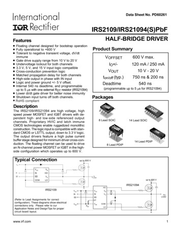
High Voltage XLPE Cable SystemsTechincal User Guide2.3 Inductance, Inductive reactanceThe operating inductance in general depends onthe relation between the conductor axis spacingand the external conductor diameter. Practically,two cases have to be considered:Laying formation: flatLaying formation: trefoilThe mean operating inductance for the threephases calculates asa a'Lm 2 10 4 ln 0,779 rLa2raThe operating inductance for all three phasescalculates as: aL 2 10 4 ln 0,779 rL2ra (H/km) witha Phase axis distance (mm)rL Diameter of conductor over innersemiconducting layer (mm)a (H/km) witha’ 3 2 a Mean geometric distance (mm)a Phase axis distance (mm)rL Diameter of conductor over innersemiconducting layer (mm)The inductive reactance of the cable systemcalculates for both cases as:X L [ /km]with Angular frequency (1/s)2.4 Losses in cablesVoltage-dependent and current-dependent powerlosses occur in cables.I)Voltage-dependent lossesVoltage-dependent power losses are caused bypolarization effects within the main insulation.They calculate to:Pd U o2 C b tan (W/km)withUo Operating voltage (kV) Angular frequency (1/s)Cb Operating capacity (µF/km)Dielectric power loss factors tan for typical cableinsulations are:XLPE(1,5 to 3,5) 10–4EPR(10 to 30) 10–4Oil cable(18 to 30) 10–4II) Current-dependent lossesThe current-dependent losses consist of thefollowing components:- Ohmic conductor losses- Losses through skin effect- Losses through proximity effect- Losses in the metal sheathOhmic conductor lossesThe ohmic losses depend on material andtemperature. For the calculation of the ohmiclosses R I², the conductor resistance stated for20 C (Ro) must be converted to the operatingtemperature of the cable:R Ro [1 ( - 20 C )] [ /km]with 0.0393 for Copper 0.0403 for AluminiumThe conductor cross-section and admissible DCresistances at 20 C (Ro) correspond to thestandards series pursuant to IEC 60228.Brugg CablesPage 7
High Voltage XLPE Cable SystemsTechincal User GuideLosses through skin effectThe losses caused by the skin effect, meaning thedisplacement of the current against the conductorsurface, rise approximately quadratic with thefrequency. This effect can be reduced withsuitable conductor constructions, e.g. segmentedconductors.Losses through proximity effectThe proximity effect detects the additional lossescaused by magnet fields of parallel conductorsthrough eddy currents and current displacementeffects in the conductor and cable sheath. Inpractice, their influence is of less importance,because three-conductor cables are only installedup to medium cross-sections and single-conductorcables with large cross-sections with sufficientaxis space. The resistance increase throughproximity effects relating to the conductorresistance is therefore mainly below 10%.Losses in the metal sheathHigh voltage cables are equipped with metalsheaths or screens that must be earthedadequately.Sheath losses occur through:- Circulating currents in the system- Eddy currents in the cable sheath(only applicable for tubular types)- Resulting sheath currents caused by inducedsheat voltage (in unbalanced earting systems)The sheath losses, especially high circulatingcurrents, may substantially reduce the currentload capacity under certain circumstances. Theycan be lowered significantly through specialearthing methods.2.5 Earthing methods, induced voltageHigh voltage cables have a metallic sheath, alongwhich a voltage is induced as a function of theoperating current. In order to handle this inducedvoltage, both cable ends have to be bondedsufficiently to the earthing system. The followingtable gives an overview of the possible methodsand their characteristics:Standing voltageat cable endsSheath voltagelimiters requiredBoth-end bondingNoNoSubstations, short connections,hardly applied for HV cables,rahter for MV and LV cablesSingle-end bondingYesYesUsually only for circuit lengthsup to 1 kmOnly at crossbonding pointsYesLong distance connectionswhere joints are requiredEarthing methodCross-bondingTypical applicationOverview of earthing methods and their characteristicsBoth-end bondingBoth ends of the cable sheath are connected tothe system earth. With this method no standingvoltages occur at the cable ends, which makes itthe most secure regarding safety aspects. On theother hand, circulating currents may flow in thesheath as the loop between the two earthingpoints is closed through the ground. Thesecirculating currents are proportional to theconductor currents and therefore reduce the cableampacity significantly making it the mostdisadvantegous method regarding economicaspects.UxInduced voltage distribution at both-end bondingBrugg CablesPage 8
High Voltage XLPE Cable SystemsTechincal User GuideSingle-ended BondingOne end of the cable sheath is connected to thesystem earth, so that at the other end (“openend”) the standing voltage appears, which isinduced linearily along the cable length. In orderto ensure the relevant safety requirements, the“open end” of the cable sheath has to beprotected with a surge arrester. In order to avoidpotential lifting in case of a failure, both earthpoints have to be connected additionally with anearth continuity wire. The surge arrester (sheathvoltage limiter) is designed to deflect switchingand atmospheric surges but must not trigger incase of a short-circuit.earth continuityUxInduced voltage distribution at single-end bondingCross-bondingThis earthing method shall be applied for longerroute lengths where joints are required due to thelimited cable delivery length. A cross-bondingsystem consists of three equal sections with cyclicSection 1sheath crossing after each section. Thetermination points shall be solidly bonded to earth.Section 2Section 3L1L2L3UxInduced voltage distribution at cross-bondingAlong each section, a standing voltage is induced.In ideal cross-bonding systems the three sectionlengths are equal, so that no residual voltageoccurrs and thus no sheath current flows. Thesheath losses can be kept very low with thismethod without impairing the safety as in the twosided sheath earthing.Brugg CablesVery long route lengths can consist of severalcross-bonding systems in a row. In this case, it isrecommended to maintain solid bonding of thesystem ends in order to prevent travelling surgesin case of a fault.In addition to cross-linking the sheaths, theconductor phases can be transposed cyclicly. Thissolution is especially suited for very long cableengths or parallel circuits.Page 9
High Voltage XLPE Cable SystemsTechincal User GuideCalculation of the induced voltageThe induced voltage Ui within a cable systemdepends on the mutual inductance between coreand sheath, the conductor current and finally onthe cable length:and where LM is the mutual inductivity betweencore and sheath (H/km).U i X M I L (V)The mutual inductivity between core and sheathLM calculates as follows:withXM Mutual inductance between core and sheath( /km)I Conductor current per phase (A)L Cable lengthTwo cases must be considered for thedetermination of the maximum occurring voltageand for the dimensioning of the surge arresters:I IN Normal operating current (A)I Ic Three-pole Short-circuit current (A)The mutual inductance between core and sheathcalculates from the following formula:X M LM ( /km)For installation in trefoil formation: 2aL M 2 10 7 ln dM (H/km) For installation in flat formation: 2 3 2 a (H/km)L M 2 10 7 ln dM witha Axial spacing (mm)dM Mean sheath diameter (mm)with Angular frequency (1/s)2.6 Short-Circuit current capacityFor the cable system layout, the maximum shortcircuit current capacity for both – the conductorand the metallic sheath – have to be calculated.Both values are depending on- the duration of the short-circuit current- the material of the current carrying component- the type of material of the adjacentcomponents and their admissible temperatueThe duration of a short circuit consists of theinherent delay of the circuit breaker and the relaytime.Short-Circuit current capacity of conductorsThe following table contains the uctors acc. to IEC 60949 with a duration of1 second for the different conductor and insulationtypes.Brugg AkA1s; 90.250 C1s; 85.165 41157683906066724752573842432831342325Admissible short-circuit currentsPage 10
High Voltage XLPE Cable SystemsBased on these reference values, the short-circuitcurrents for other durations can be converted withthe following formula:I k,x 1tc I k ,1swithIkx Short-circuit current during x seconds [kA]tc Duration of short-circuit [s]Ik,1s Short-circuit current during 1 second [kA]The above stated values were calculated on anon-adiabatic basis, which means that heatTechincal User Guidetransfer from the current carrying componen to itsadjacent components is allowed.Short-Circuit current capacity of metallic sheathsIn addition to the above mentioned, the shortcircuit current capacity of metallic sheathsdepends on their layout. The short-circuit currentcapacity is different for tubular sheats and wirescreens, but generally the total short-circuitcurrent capacity of a metallic sheath is the sum ofthe capacity of its components.Typical metallic sheath layouts with theirconstructional details are listed in a separatesection.2.7 Dynamic forcesRadial forceSingle-core cables have to be fixed in theirposition at certain intervals. The calculation ofdynamic forces for cable systems is important forthe determination of the fixing interval and thelayout of the fixing devices. It has to bedistinguished between radial (e.g. clamps,spacers) and tangential (belts etc.) forces.Fs Dynamic force [kN/m] Layout factor (typical value for mid phase:0.866)The amplitude of a dynamic force in general iscalculated applying the following formula:Tangential force2 10 7 I s2Fs (kN/m)awitha Phase axis distance (mm)The dynamic force that a spacer has to absorb is:Fr FsThe dynamic force that a fixing belt has to absorbis:Ft FsFs Dynamic force [kN/m] Layout factor (value for trefoil: 0.5)I s 2 Icwhereinls Impulse short-circuit current [kA] surge factor (usually defined as 1.8)lc Short-circuit current [kA]2.8 Metallic sheath typesThe metallic sheath of high voltage XLPE singlecore cables has to fulfill the following electricalrequirements:Conducting the earth fault currentReturning the capacitive charging currentLimitation of the radial electrostatic fieldShielding of the electromagnetic fieldBrugg CablesSince high voltage XLPE cables are very sensitiveto moisture ingression, the metallic sheath alsoserves as radial moisture barrier. There areseveral modes of preventing water and moisturepenetrating into the cable and travelling within italong its length. Solutions for closed metallicsheathes can be based on welding, extruding orgluing. Some typical sheath layouts as availablefrom Brugg Cables are shown in the followingtable.Page 11
High Voltage XLPE Cable SystemsTechincal User GuideTypical metallic sheath typesBrugg type XDRCU-ALTBrugg type XDRCU-ALTAluminium laminated sheathwith Copper wire screenAluminium laminated sheathwith Copper wire screen andintegrated fibres for temperature sensingFeatures:- Low weight- Low losses- Low costFeatures:- Low weight- Low losses- Low costTypical application:Installation in tunnels, trenches or ductsTypical applications:Installation in tunnels, trenches or ductsBrugg type XDRCU-CUTBrugg type XDCUW-TCopper laminated sheathwith Copper wire screenCopper corrugated sheathFeatures:- Low weight- Low losses- Low costFeatures:- 100% impervious to moisture- flexible- resistant to deformation, pressure andcorrosion- weldedTypical applications:Installation in tunnels, trenches or ductsTypical applications:All installations in soil, especially in locationswith shallow ground water levelSpecial application:Installation in vertical shafts (up to 220 m)Brugg type XDPB-TBrugg type XDRCU-PBTLead sheathLead sheathwith Copper wire screenFeatures:- 100% impervious to moisture- seamless- extrudedFeatures:- 100% impervious to moisture- seamless- extruded- increased short-circuit capacity throughadditional copper wire screenTypical applications:All installations in soilTypical applications:All installations in soilBrugg CablesPage 12
High Voltage XLPE Cable SystemsTechincal User Guide3. XLPE Cable System StandardsBrugg Cables XLPE cable systems are designed to meet requirements set in national and internationalstandards. Some of these are listed below.IECXLPE cable systems specified according to IEC (International Electrotechnical Commission) are amongmany other standards accepted.Some frequently used standards are:IEC 60183Guide to the selection of high-voltage cables.IEC 60228Conductors of insulated cables.IEC 60229Tests on cable oversheaths which have a special protective function and are applied byextrusion.IEC 60287Electric cables – Calculation of the current rating.IEC 60332Tests on electric cables under fire conditions.IEC 60811Common test methods for insulating and sheathing materials of electric cables.IEC 60840Power cables with extruded insulation and their accessories for rated voltage above30 kV (Um 36 kV) up to 150 kV (Um 170 kV). Test methods and requirements.IEC 60853Calculation of the cyclic and emergency current rating of cables.IEC 61443Short-circuit temperature limits of electric cables with rated voltages above30 kV (Um 36 kV)IEC 62067Power cables with extruded insulation and their accessories for rated voltage above150 kV (Um 170 kV) up to 500 kV (Um 550 kV) - Test methods and requirementsCENELECIn Europe, cable standards are issued by CENELEC. (European Committee for ElectrotechnicalStandardisation.) Special features in design may occur depending on national conditions.HD 632Power cables with extruded insulation and their accessories for rated voltage above36 kV (Um 42 kV) up to 150 kV (Um 170 kV). Part 1- General test requirements.Part 1 is based on IEC 60840 and follows that standard closely.HD 632 is completed with a number of parts and subsections for different cables intended to beused under special conditions which can vary nationally in Europe.ICEA / ANSI / AEICFor North America cables are often specified according to- AEIC (Association of Edison Illuminating Companies)- ICEA (Insulated Cable Engineers Association)- ANSI (American National Standards Institute) orThe most frequently standards referred to are:AEIC CS7-93Specifications for crosslinked polyethylene insulated shielded power cables rated69 through 138 kV.ANSI / ICEA S-108-720-2004 Standard for extruded insulation power cables rated above 46 through345 kVISO StandardsOur systems comply with the requirements of ISO 9001 and ISO 14001 and are certified by Bureau VeritasQuality International.Brugg CablesPage 13
High Voltage XLPE Cable SystemsTechincal User Guide4. Technical data sheets500 / 290 kV XLPE Cable - Technical data and Ampacity400 / 230 kV XLPE Cable - Technical data and Ampacity345 / 200 kV XLPE Cable - Technical data and Ampacity220 / 127 kV XLPE Cable - Technical data and Ampacity132 / 76 kV XLPE Cable - Technical data and AmpacityBrugg CablesPage 14
500/290 kV XLPE CableSingle-core XLPE High Voltage Cablewith Aluminium laminated sheathProduction processThe inner semiconductive layer, the Copper conductor, stranded, cross-sections ofXLPE main insulation and the outer1000 sqmm and above segmented, optionallysemiconductive layer are extruded in awith longitudinal water barriersingle operation. Inner semiconductive layer, firmly bonded to theSpecialfeatures of metallic sheathXLPE insulationCable layoutXDRCU-ALT500/290 kVCopper wire screen as short-circuitcurrent carrying component Aluminium foil, overlapped,0,25 mm thick, as radial diffusionbarrier Low weight, low cost,internationally proven designApplicable standardsIEC 62067 (2001) XLPE main insulation, cross-linked Outer semiconductive layer, firmly bonded tothe XLPE insulation Copper wire screen with semi-conductiveswelling tapes as longitudinal water barrier Aluminium lamninated sheath HDPE oversheath, halogen-free, as mechanicalprotection, optionally: with semi-conductiveand/or flame-retardant layerTechnical dataCopper conductorcross-sectionOuterdiameterapprox.Cable weightappox.CapacitanceImpedance(90 C, 50 Hz) SurgeimpedanceMin. bendingradiusMax. 9002900384860728496120150Buried in soilBuried in soil Buried in soil Buried in soil In free air In free air 0.71.00.71.0--mmAmpacity Load 21944206823262670mmCalculation basis:Conductor temperature 90 C, 50 Hz, soil temperature 25 C, laying depth 1200 mm, soil thermal resistivity 1.0 Km/W,phase distance at flat formation 30 cm, air temperature 35 - Earthing method: Single-end bonding or Cross-bonding 05.2006 Subject to modifications1/1
400/230 kV XLPE CableSingle-core XLPE High Voltage Cablewith Aluminium laminated sheathProduction processThe inner semiconductive layer, the Copper conductor, stranded, cross-sections ofXLPE main insulation and the outer1000 sqmm and above segmented, optionallysemiconductive layer are extruded in awith longitudinal water barriersingle operation. Inner semiconductive layer, firmly bonded to theSpecialfeatures of metallic sheathXLPE insulationCable layoutXDRCU-ALT400/230 kVCopper wire screen as short-circuitcurrent carrying component Aluminium foil, overlapped,0,25 mm thick, as radial diffusionbarrier Low weight, low cost,internationally proven designApplicable standardsIEC 62067 (2001) XLPE main insulation, cross-linked Outer semiconductive layer, firmly bonded tothe XLPE insulation Copper wire screen with semi-conductiveswelling tapes as longitudinal water barrier Aluminium lamninated sheath HDPE oversheath, halogen-free, as mechanicalprotection, optionally: with semi-conductiveand/or flame-retardant layerTechnical dataCopper conductorcross-sectionOuterdiameterapprox.Cable weightappox.CapacitanceImpedance(90 C, 50 Hz) SurgeimpedanceMin. bendingradiusMax. 150Buried in soilBuried in soil Buried in soil Buried in soil In free air In free air 0.71.00.71.0--mmAmpacity Load ulation basis:Conductor temperature 90 C, 50 Hz, soil temperature 25 C, laying depth 1200 mm, soil thermal resistivity 1.0 Km/W,phase distance at flat formation 30 cm, air temperature 35 - Earthing method: Single-end bonding or Cross-bondingValues apply for cables with rated voltages from 380 kV to 400 kV acc. to IEC 62067 05.2006 Subject to modifications1/1
345/200 kV XLPE CableSingle-core XLPE High Voltage Cablewith Aluminium laminated sheathProduction processThe inner semiconductive layer, the Copper conductor, stranded, cross-sections ofXLPE main insulation and the outer1000 sqmm and above segmented, optionallysemiconductive layer are extruded in awith longitudinal water barriersingle operation. Inner semiconductive layer, firmly bonded to theSpecialfeatures of metallic sheathXLPE insulationCable layoutXDRCU-ALT345/200 kVCopper wire screen as short-circuitcurrent carrying component Aluminium foil, overlapped,0,25 mm thick, as radial diffusionbarrier Low weight, low cost,internationally proven designApplicable standardsIEC 62067 (2001)ANSI / ICEA S-108-720-2004 XLPE main insulation, cross-linked Outer semiconductive layer, firmly bonded tothe XLPE insulation Copper wire screen with semi-conductiveswelling tapes as longitudinal water barrier Aluminium lamninated sheath HDPE oversheath, halogen-free, as mechanicalprotection, optionally: with semi-conductiveand/or flame-retardant layerTechnical dataCopper conductorcross-sectionOuterdiameterapprox.Cable weightappox.CapacitanceImpedance(90 C, 50 Hz) SurgeimpedanceMin. bendingradiusMax. 150Buried in soilBuried in soil Buried in soil Buried in soil In free air In free air 0.71.00.71.0--mmAmpacity Load ulation basis:Conductor temperature 90 C, 50 Hz, soil temperature 25 C, laying depth 1200 mm, soil thermal res
Voltage-dependent and current-dependent power losses occur in cables. I) Voltage-dependent losses Voltage-dependent power losses are caused by polarization effects within the main insulation. They calculate to: 2 tan d o P U C b (W/km) with Uo Operating voltage (kV) Angular frequency (1/s) Cb Operating capacity (µF/km)