Transcription
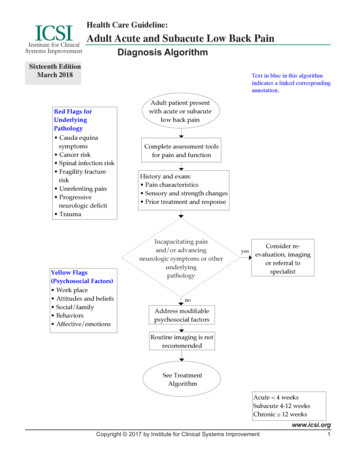
&MODERNTESTINGDIAGNOSISOF POWERCABLESUSING DAMPED AC VOLTAGESB Y E D WA R D GU L S K I A N D ROG IER J ONG EN , Ons i te H V S oluti ons ag , Sw i tze rl a n d ANDR A L PH PATTE R S ON , Powe r Prod ucts & S oluti ons LLC , Un i te d StatesModern on-site testing and diagnosis of powercables up to 230 kV consists of voltage testing,partial discharge detection, and dissipationfactor measurements. Since the last 10 years inaddition to continuous ac or VLF energizing,the use of damped ac energizing is gettingmore and more worldwide attention. Havingin mind the forthcoming IEEE 400.4 guidefor the use of damped ac testing in this paperthe application of damped ac voltages foron-site testing and diagnosis of undergroundpower cables up to 230 kV will be presented.Insulation failure of a power cable can occuras a result of the normal operational voltageor during a transient voltage due to lightningor switching surges. Examples of failures areshown in Figure 1.Most failures occur as a result of localizedelectrical stresses that are higher than thedielectric strength of the dielectric materialsin the area of the localized stress or if the bulkdielectric material degrades to the point whereit cannot withstand the applied voltage. To findFigure 1: Examples of Insulation Defects in Power Cables:Distribution cables: (a) bad positioning of field grading; (b) large crack in the center of an epoxy resin joint;(c) interfacial problems in a termination; (d) connector sharp edges inside mass insulated cable terminationTransmission cables: (e) termination of 132 kV XLPE cable with unsealed bottom resulting in contaminationand moisture ingress in side insulator; (f, h) cable movement due to expansion of oil due to high temperatures,directly resulting in cracks and voids in joint insulation with final breakdown; (g) electrical treeing in 150 kVgas pressure cables resulting in long term insulation degradation and finally cable breakdown58ï WINTER2014SPRING 2015www.netaworld .orgRISK ASSESSMENTANDOTHERACREVISIONS–MODERN TESTING AND DIAGNOSIS OF POWERCABLES USINGDAMPEDVOLTAGESNEW TONFPA 70E-201558Spring 2015NETAWORLD
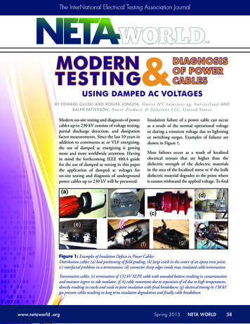
INDUSTRY TOPICSFigure 2: Example of On-site Testing Using Sinusoidal Damped ac Voltages (a) diagnostic testing by damped ac system 30kV of a 3 km long 10 kV XLPE insulated cable; (b) after-laying testing by a damped ac 190 kV system of a 12 km long 110kV XLPE cable; (c) after-laying testing by a damped ac 270 kV system of a 6 km long 150 kV XLPE cablethese defects prior to a failure, on-site tests, asshown in Figure 2, are applied to assess thequality and cable system integrity as well as theavailability and reliability of the cable circuit.In relation to the applied damped ac testingprocedures, the IEEE 400.4: Guide for FieldTesting of Shielded Power Cable Systems Rated5 kV and above with Damped AlternatingCurrent Voltage (Damped ac), document isunder balloting. This guide includes practicalconsiderations, based on user experienceduring the last 10 years in relation toseveral IEC standards. Examples of suchconsiderations include the number of dampedac excitations applied during testing and theminimum recommended test voltage level.User feedback has confirmed the followingtest parameters:(a) Maximum damped ac test voltage levels:a. For MV cables (6-35 kV) up to 2.0U₀ (U₀ is the rated phase to groundvoltage)b. For HV cables (36-150 kV) up to 1.73– 2.0 U₀c. For EHV cables (150-230 kV) up to1.4 – 1.7 U₀(b) Number of damped ac excitations atmaximum applied damped ac voltagewithstand level: 50.In this paper, the use of damped sinusoidal acvoltages (damped ac) for monitored testing ofpower cables will be discussed based on generalconsiderations and practical examples.ON- S ITE E NE RGIZINGME THOD AT DAMPE DAC VOLTAGE SDamped ac testing can be used as a simplewithstand test or in combination with partialdischarge (PD) and dissipation factor (DF)measurements for new installed and service-agedcables, Figure 3. The use of damped ac voltagesfor testing power cables is in compliance withrelevant IEC, IEEE, and Cigre internationalstandards and guidelines.Figure 3: General Overview of Damped ac (DAC) Field TestPossibilities for Different Testing Goals of Cable Systems [IEEE 400.4/D8 under balloting]RISK ASSESSMENTREVISIONS–MODERNTESTING AND OTHERDIAGNOSISOF POWERCABLES USING DAMPED AC VOLTAGESNEW TO NFPA 70E-2015www.netaworld.orgSpring 2015NETAWORLDNETA WORLDï5959
INDUSTRY TOPICSFigure 4: Schematic Overview of One Damped ac Excitation. Themaximum damped ac voltage level is determined by the voltage peakvalues (Vdamped ac) and respective RMS-values (Vdamped ac/ 2) of the 1stdamped ac cycle.Figure 5: Schematic overview of withstand test by dampedsinusoidal ac voltage excitations. The duration of the test is determinedby the number of damped ac excitations which are applied to the powercable at a selected damped ac test voltage. The maximum dampedac withstand voltage level is determined by the voltage peak valuesVdamped ac and respective rms-values Vdamped ac/ 2 of the first damped cycle.Figure 6: Schematic Diagram of Damped ac (DAC) Systems for On-siteTesting and PD Detection of Distribution and Transmission Power Cables60 SPRING 2015www.netaworld .orgTo generate damped ac voltages with durationsof a few tens of cycles of ac voltage at frequenciesup to a few hundreds of Hz, a test systemhas been developed. This method is used toenergize and to test on-site power cables withsinusoidal ac frequencies. The system consistsof a digitally controlled high voltage powersupply to energize capacitive load of powercables with large capacitance (e.g., 10 µF),Figure 6. With this method, the cable undertest is energized during a time tcharge Umax Ccable/Iload with continuously increasing voltage, seeFigure 4. During this phase the test object isstressed with an increasing unipolar voltage.The energizing time depends on the maximumavailable load current of the voltage supply,the test voltage, and the capacitance of the testobject. As a result, due to ac field distribution,dc stress, steady-state condition, and spacecharges are not applied to the test object, andthe damped ac stress as applied to the testobject can be considered as similar to factorytesting conditions.At maximum selected test voltage, a speciallydesigned solid-state switch connects an aircore inductor to the cable sample in a closingtime of 1μs. Due to relatively low cableinductance, no transient overvoltages willoccur in the test object. At this moment,the series of ac voltage cycles starts with theresonance frequency of the circuit fdamped ac 1/(2Π (L . Ccable)) where L represents the fixedinductance of the air core and Ccable representsthe capacitance of the cable sample, Figure 6.The air core inductor has a low loss factorand design, resulting in a slowly decayingac waveform of test voltage applied to thecable sample. During a number of ac voltagecycles, the PD signals are initiated in a waysimilar to 50(60) Hz inception conditions.This procedure can be repeated for multipleexcitations followed after each other toperform a voltage withstand test as shown inFigure 5.The DF can be measured with the decaycharacteristics of the damped ac voltagewave and the evaluation of the DF can beMODERN TESTING AND DIAGNOSIS OF POWER CABLES USING DAMPED AC VOLTAGESSpring 2015NETA WORLD60
INDUSTRY TOPICSespecially valuable for finding insulation ageingdevelopment in paper-oil insulated cables.DA MPE D AC VO LTAGEW I T H S TA ND T EST I N GThe application of withstand tests can bedivided into two classes:1. U nmonitored damped ac hold test:a number of damped ac excitationsis applied and the ability to hold themaximum damped ac voltage (i.e., nobreakdown occurs) is recorded as seen bythe black dotted lines in Figures 7a and7b. The intent of a simple damped acwithstand test is to cause weak points inthe cable insulation to fail during voltageapplication (with minimal fault current)at a time when the impact of the failureis low (no systems or customers affected)and repairs can be made more costeffectively. If a failure occurs during thetest, see the vertical dotted line in Figure7c breakdown, then the failure should belocated through a fault location processand repaired and the circuit retested. Theresults of these tests are described as eitherpass or fail.2. M onitored damped ac hold test: a numberof damped ac excitations are applied andone or more additional attributes aremeasured and used to determine whetherthe cable passes or fails the damped ac test.In the graphs in Figure 7, the black dottedlines represent the applied damped acvoltage and the grey dotted lines representthe PD detection. Due to additionalinformation as provided by PD detection,the monitoring insulation propertiesduring a damped ac withstand test, andthe effect of the test voltage during itsapplication can improve the evaluation ofthe insulation condition.The applied maximum test voltage levels forvoltage withstand testing of newly installedcables are given in Table 1.Figure 7: Schematic Overview of Three Different Situations of Damped ac (DAC) Voltage WithstandTest: (a, b) during selected number of Ndamped acexcitations (black dotted lines) no breakdown has occurredand alternatively above the PD background noise PD has been observed or not (grey dotted lines); (c) beforethe selected number of Ndamped acexcitations for the damped ac withstand test has been applied breakdown hasoccurred, and above the PD background noise PD has been observed.MODERN TESTING AND DIAGNOSIS OF POWER CABLES USING DAMPED AC VOLTAGESwww.netaworld .orgSpring 2015NETAWORLDNETA WORLD 6161
INDUSTRY TOPICSTable 1: Damped ac test voltages levels (20 Hz–500 Hz) as used fordamped ac testing (50 damped ac excitations) of recently installed powercables [IEC 60502, IEC 60840, IEC 62067].Power cable rated voltageU [kV] phase-to-phaseU0 [kV]DAC test voltage level VT[kVpeak] 0-16187212220-230127254PRACTICAL E X AMPLE SThe application of damped ac voltages fortesting and diagnosis of transmission powercables up to 230 kV has a history of morethan 10 years. In this section, examples arepresented and discussed to highlight theimportance of monitored testing.Example 1: A newly installed 2.1 km long,10 kV XLPE insulated underground cablecircuit has been tested in accordance withthe IEC 60502 Standard which recommendsvoltage withstand testing using sinusoidalac voltage up to 2 U₀. Monitored withstandtesting was performed by using a dampedac resonant circuit with damped sinusoidalac voltages at 224 Hz for 50 damped acexcitation at 2.0 U₀. For the duration of thewithstand test, standardized PD detection wasapplied. During the application of damped acover-voltage, no breakdown was observed. Itfollows from Figures 8 and 9 that internal PDactivity was registered in a joint in phase L3.The joint was investigated and the PD sourceSand in between the crimp tubesVoids between the crimp tubesdue to improper crimpingPD level:PDIV L3 1.7 UOPD level L3 200pC @ PDIVPD level L3 800[C @ 2xUOPD location:L3: 1 joint at 955 meterFigure 8: PD Results of an After-laying Testing of a 10 kV2.1 km Long XLPE Cable Section62 SPRING 2015www.netaworld .orgFigure 9: Investigation of the Joint at 955 m Location Having PDup to 800 pC at 2 U₀MODERN TESTING AND DIAGNOSIS OF POWER CABLES USING DAMPED AC VOLTAGESSpring 2015NETA WORLD62
INDUSTRY TOPICSwas identified in the crimping tube. After therepair, the complete cable system was free ofPD and the test was considered successful.Example 2: Maintenance testing wasperformed on a service-aged 2.0 km long 30 kVXLPE insulated underground circuit. Startingfrom 0.6U₀, PD activity up to 9000 pC wasregistered in one of the joints. Increasing thedamped ac test voltage up to 1.7 U₀ resultedin concentrated PD activity in this particularjoint (Figure 10). Due to the fact that thePD inception voltage is below U₀, increasednetwork stresses may result in inception of,and an increase in PD activity during normaloperation. Recommended replacement of thejoint was accomplished, and the investigationconfirmed a PD source (Figure 11).Example 3: A newly installed 13.3 kmlong, 220 kV XLPE insulated undergroundcable circuit was tested using a damped acresonance system at 49 Hz, applying up to1.3 U₀, (Figures 12-14). Monitored withstandtesting was performed. As the damped actest voltage was increased starting from 0.2U₀, PD activity was observed in phase L1.An increase in the test voltage resulted in anincrease of PD activity, At 0.4 U₀ test voltage,a breakdown at the discharging site occurred.PD mapping revealed the PD concentrationat 5.3 km indicated the breakdown positionin the cable. The defect produced PD beforean actual breakdown occurred, and with TDRanalysis, the PD defect location could bedetermined. The other two phases fulfilled theafter laying conditions and successfully passedthe test. No internal PD activity in the cableinsulation and accessories and no breakdownoccurred during the tests of the other phases.The measurement was repeated from the otherend of the L1 cable. The PD activity occurringbefore the breakdown could be localized at 8km, which is the same location seen from theoriginal tests (13.3 – 8 5.3 km).Example 4: Maintenance testing (damped acfrequency 62 Hz) was performed on a serviceaged 35-year old 2.2 km long 66 kV XLPEinsulated underground circuit: see FiguresFigure 10: PD Results of a Maintenance Testing of a 10 kV 2.0 km LongXLPE Cable SectionFigure 11: Investigation of the Joint at 415 m Location Having PD upto 9000 pC at 1.7 U₀Figure 12: On-site Testing of a 220 kV 13.3 km Long XLPE CableCircuit:The damped ac system HV30 is connected to one of the cable section phases.MODERN TESTING AND DIAGNOSIS OF POWER CABLES USING DAMPED AC VOLTAGESwww.netaworld .orgSpring 2015NETAWORLDNETA WORLD 6363
INDUSTRY TOPICSFigure 13: Damped ac V
several IEC standards. Examples of such considerations include the number of damped ac excitations applied during testing and the minimum recommended test voltage level. User feedback has confirmed the following test parameters: (a) Maximum damped ac test voltage levels: a. For MV cables (6-35 kV) up to 2.0 U₀ (U₀ is the rated phase to ground voltage) b. For HV cables (36-150 kV) up to 1 .