Transcription
BHEL-HPVP,VISAKHAPATNAMTECHNICAL SPECIFICATION OF 500KVA COMPACT SUBSTATION &RMURef no: WE-29082020-01TECHNICAL SPECIFICATION FOR PACKAGEDSUBSTATION/COMPACT SUBSTATION AND 11KV RMUPROJECT: SITE ENABLING WORKS FOR FABRICATION ATSEA FRONT FACILITYPage 1 of 31
BHEL-HPVP,VISAKHAPATNAMTECHNICAL SPECIFICATION OF 500KVA COMPACT SUBSTATION &RMURef no: WE-29082020-01CONTENTSCLAUSE NO.DESCRIPTIONPAGE NO.1.00.00 INTENT OF SPECIFICATION32.00.00 CODES&STANDARDS33.00.00 SCOPE & SPECIFIC REQUIREMENTS34.00.00 DESIGN CRITERIA85.00.00 DESIGN REQUIREMNT OF 11KV CSS86.00.00 GENERAL REQUIREMENTS127.00.00 PREDISPATCH INSPECTION138.00.00 TRAINING (OPTIONAL)139.00.00 COMISSIOING SPARES1310.00.00 MATERIAL CODES (BHEL USE)1311.00.00 TYPICAL SLD’S1412.00.00 DATA SHEET1613.00.00 DOCUMENTATION2114.00.00 DRAWINGS&DATA MANUALS2215.00.00 MAKE OF COMPONENTS2315.00.00 PRICE FORMAT25ANNEXURE-1(DEVIATION SCHEDULE)ANNEXURE-2(PACKAGE EXECUTION MILESTONES/SCHEDULE)ANNEXURE-3(CHECK LIST)ANNEXURE-4(QAP Guidelines)Page 2 of 3126272831
BHEL-HPVP,VISAKHAPATNAMTECHNICAL SPECIFICATION OF 500KVA COMPACT SUBSTATION &RMURef no: WE-29082020-01TECHNICAL SPECIFICATION OF COMPACT SUBSTATION1. INTENT OF SPECIFICATIONThis specification is intended to cover the design, manufacture, assembly, testing atmanufacturer's works, supply & delivery, properly packed for transport of the PackagedSubstation(PSS)/Compact Substation(CSS), 11kV Ring Main Unit (RMU) and supervision oferection & commissioning as specified herein under, complete with all accessories, fittingsand auxiliary equipment as required for efficient &trouble-free operation. Thepackaged(PSS)/Compact substation shall be suitable for installation and operation near the seafront.2. CODES & STANDARDS:2.1 All equipment and material shall be designed manufactured and tested in accordance withthe latest applicable IEC standards.2.2 The Package Sub-station offered shall in general comply with the latest issues includingamendments of the following standards.TitleStandardsHigh Voltage Low Voltage Pre-Fabricated SubstationIEC:61330/62271-202High Voltage SwitchesIEC 60265Metal Enclosed High Voltage SwitchgearIEC 60298/62271-200High Voltage SwitchgearIEC 60694/62271-100Low Voltage Switchgear and Control gearIEC 60439/60947Power TransformersIEC 600763. SCOPE & SPECIFIC REQUIREMENTS3.1 Supply of 1 nos. 500kVA, 11kV, Package Substations with fault level of 21KA for 1 sec.Following equipment details part of each Package substation.S. Noi)Description11kV RMU: Quantity:1 no.Three way 11KV Non-Extensible Ring Main Unit Compact switchgear consisting of630A two numbers SF6 insulated fixed manual fault making / Load break Switches &630A one number of Fixed manual SF6 insulated Vacuum circuit breaker. SF6insulated Vacuum circuit breakers with self- powered relay having Transformerprotection, over current and earth fault protection. Interconnection between RMU andtransformer shall be by using suitable Copper unarmoured 11KV (UE) 1CX1RX95sq.mm per phase cable which is in the scope of Bidder. Incomer break switches shallPage 3 of 31
BHEL-HPVP,VISAKHAPATNAMTECHNICAL SPECIFICATION OF 500KVA COMPACT SUBSTATION &RMURef no: WE-29082020-01be suitable for termination of 2 runs of 3C X 240 Sq.mm aluminium armoured XLPECableMake of RMU switchgear: ABB/ Siemens/ Alstom / Schneider/L&T make only.Make of relay to be used with VCB: L&T/ABB / Areva / Siemens / Schneider makeonlyTransformer Feeder Metering3 Nos 11KV Single core Ring type metering CTs with 40/5A or 50/5A for eachtransformer feeder.ii)500kVA 11kV/0.433KV Dry type/Oil type Transformer: Quantity: 1 No.500 KVA, 11KV / 0.433V, Dyn11, Dry Type /Oil type Transformer with off circuit taplinks 5% to -5% @ 2.5% on HT side of transformer with WTI Scanner with Alarm andtrip contact.Make of the transformer: Should be same as CSS.Impedance, no-load/ load losses, efficiency, temperature rise above ambient of windingof the transformer should be as per IS/IEC/CBIP standards.Suitable surge arrestor shall be provided between VCB & Transformeriii)LV Switchgear: (Inside CSS)Quantity:1 No: 800A ACB Incomer1 No: 800A MCCB outgoing feeder1 No. 200A MCCB Outgoing Feeder1 No.100A MCCB Outgoing feeders415V indoor LV panel with Aluminum Bus bars, fabricated using CRCA sheet steel,Ingress Protection IP4X, Compartmentalized complete with internal wiring consisting offollowing.Incomer: 800 A, TPN, 415V, 3P, 50Hz, 21KA, Fixed manual type ACB withMicroprocessor based O/L, S/C, and E/F (IDMTL Inst.) release.Rated Insulation Voltage Ui 1000V, Utilization category BLT Switchgear should be suitable for termination of 2run X 3 ½ C X 240 Sq.mmaluminum armored Cable.Make of the ACB - L&T/ Siemens / GE/ABB/ Schneider /Areva make only.Page 4 of 31
BHEL-HPVP,VISAKHAPATNAMTECHNICAL SPECIFICATION OF 500KVA COMPACT SUBSTATION &RMURef no: WE-29082020-01LV Switchgear : Metering (for Incomer)Maximum demand controller as per the specification at pg no:22 shall be provided(Conzerv/L&T/Secure/Schneider/elmeasure) – 1 No. Controller shall be suitable to tripthe MCCBs as per the settings.LT Metering CT’s – 3 Nos, 800/5A, Cast Resin Type, Cl – 1.0,R, Y, B, ON, OFF,TRIP LED Indicating Lamps - 6 Nos.(MakeTechnic/Vaishno/STS/Rep.) Control MCB, 6A, SP - As requirediiiLV Switchgear : Outgoing (Inside CSS)800A,200A and 100 A,TPN ,415V, 3P, 50Hz, 21KA, Fixed manual type MCCB withMicroprocessor based O/L,S/C & E/F release and trip contacts suitable forDigital Multifunction Meter with A,V,KW,KWH,PF, Cl-0.5 with RS 485 Port(Conzerv/L&T/Secure/Schneider) for each outgoing feederLT Metering CT’s, Cast Resin Type, 100/1A, Cl-0.5 (Matrix/AE/G&M Make). ControlMCB, 6A, 4P-As required (MDS/L&T/GE/SCHNEIDER/ABB)Outgoing MCCBs of LT Switchgear should be suitable for termination of 1run X 3 ½ C X240 Sq.mm aluminum armoured Cable.800A outgoing MCCB must be suitable for termination of 3 runsX3.5CX 240 Sq mm Alarmoured cable.Make of the MCCB - L&T/Siemens/GE/ABB/ Schneider /Areva make only.ivEnclosure: Quantity:1 No.Outdoor type enclosure having modular construction of Galvanized Sheet Steel. Thedegree of protection for HT & LT switchgear compartment shall be IP55 & degree ofprotection of transformer compartment of the enclosure shall be minimum IP23.Painting of the enclosure exterior shall be suitable for sea shore conditions.Eachcompartment will be provided with the door and pad locking arrangement. TheCompartment illumination lamp with door-operated switch shall be provided for eachcompartment. Structure of the substation shall be able to withstand the gross weight ofall equipment. It should be possible to transport the equipment along with transformer,RMU & LT Panel from one site to another. This shall be installed at sea front, hence,accordingly design parameters to be taken into account.vInterconnection between HT switchgear & Transformer using XLPE cable &Interconnection between Transformer & LT switchgear using high conductivityAluminium busbars(E91E) . Internal earthing connections by GI strips.viDC supply for PSS shall be through in built 24V power pack. Separate DC supplyshall be not provided for auxiliary power requirement purpose.viiAll power cables except 3Rx1Cx95 Sq.mm Cu (Between VCB and Transformer H.T) willbe by BHEL.Page 5 of 31
BHEL-HPVP,VISAKHAPATNAMTECHNICAL SPECIFICATION OF 500KVA COMPACT SUBSTATION &RMURef no: WE-29082020-013.2 Supply of 1 no. 11kV, Ring Main Unit with fault level of 21KA for 1 sec. Followingequipment details part of 11kV RMU.S. Noi)Description11kV RMU: Quantity:1 no.CCC NE with three way Motorized Outdoor Ring Main Unit consisting of three numbers630A SF6 insulated fixed motorized fault making / Load break Switch and earth switch.The RMU shall be suitable for installation at Sea shore.Enclosure: Quantity: 1 No.Outdoor type enclosure having modular construction of Galvanized Sheet Steel. Thedegree of protection shall be IP55.The painting of the enclosure exterior shall be suitablefor sea shore conditions. Each compartment will be provided with the door and padlocking arrangement. The Compartment illumination lamp with door-operated switch shallbe provided for each compartment. Structure of the substation shall be able to withstandthe gross weight of all equipment.DC supply for RMU shall be through in built 24V power pack. Separate DC supply shallbe not provided for auxiliary power requirement purpose.FEEDER REMOTE TERMINAL UNIT (FRTU)11kV RMU shall be supplied with FRTU along with necessary hardware andsoftware/gateway required for hooking with SCADA. Gateway & Protocol requirements.The Feeder RTUs should be fully integrated as per the requirements of BHEL with theMaster station based on IEC 870-5-104 protocol. The Bidder should furnish the detailsof his implementation of IEC 870-5-104 protocol and interoperability profile of thesupplied FRTU.FRTU shall be stand-alone equipment powered by 24V DC positive earthed systemcapable of performing the following functions.1. Collecting, processing and transmitting status changes, analog values,sequence of Events (SOE) and accumulator values.2. Receiving and processing digital commands from the master station(s).3. Accepting polling messages from the master station(s).4. Supporting at least three (3) serial communication ports and multipleconcurrent protocols like IEC 870-5-101, MODBUS, etc5. 1 No. Ethernet port with supporting IEC 104 / TCP/IP protocols.6. 1 No. USB 2.0 interface for diagnosis and maintenance purposes7. The RTU clock shall be provided with an internal battery backup8. It shall support 250 data points.The FRTUs shall use microprocessor based function control logic, consisting of amicroprocessor with sufficient speed and memory to accept commands via thecommunication interface and process these commands in accordance with thePage 6 of 31
BHEL-HPVP,VISAKHAPATNAMTECHNICAL SPECIFICATION OF 500KVA COMPACT SUBSTATION &RMURef no: WE-29082020-01predetermined protocol with minimal turn around delays. They shall process receivedmessages for control and data and activate the appropriate FRTU process I/O circuitsto provide a functional response to these commands and requests. The FRTU shallassemble response messages in accordance with the received messages and transmitthe responses to the requesting control Centre. The design of software and databaseshall not restrict the integration with any other master / server and future expansionbeyond the sizing parametersThe FRTU’s shall have an architecture that supports convenient installation,maintenance and expansion features. Their configuration shall include a centralprocessing module and I/O modules.CPU Modules: The Processor card must have minimum RAM of 64MB.MinimumStorage capacity possible should be 4GB (Internal or through SD card) for storing ofarchive events.I/O Modules: FRTU shall have 48 Nos. Digital Inputs, 16 Nos. Digital Outputs and 6Nos. Analog Inputs.Communication with Control CentersThe FRTU must be capable of communicating with a Master Station using the telecontrol communication protocol IEC 60870-5-104. It must be possible to communicatesimultaneously with up to 8 Master Stations.The FRTU shall provide serial communication interfaces RS232 as well as Ethernetinterfaces 10/100 BaseT for the communication in digital networksTime Management and SynchronizationThe internal time management shall be controlled by the CPU communication modules.The time resolution of the FRTU shall be 1 ms for events, scanned by the directlyconnected I/O modules. Synchronization with absolute time shall support any one of thefollowing methods. Time synchronization of the FRTU by the network control centre(NCC) via a periodically transmitted synchronization instruction with a communicationprotocol supporting this function. The FRTU time management system shall havehardware and software logic with a high control quality incorporated on the CPUcommunication modules to manage real time within the FRTU.3.3. All necessary foundation bolts and accessories are in the scope of Bidder.3.4. Supply of commissioning spares as per Annexure 3 .3.5. Supervision of installation, testing & commissioning of 11kV CSS & 11kV RMU includingFRTU is in the scope of Bidder.4. Design Criteria4.1 Package Sub-station consisting of 3 way 11KV SF6 insulated Switchgear with 630A 2no.of LBS 1 no. of 630A 11KV vacuum Circuit Breaker 11kV/415V, 500KVA, DYn11Transformer LT 415V, 800A ACB incoming with all connection, accessories, fitting &auxiliary equipment in an enclosure to supply Low-voltage energy from high-voltagesystem and 11kV RMU as detailed in this specification. The complete unit shall beinstalled on a substation plinth (base) as Outdoor substation.Page 7 of 31
BHEL-HPVP,VISAKHAPATNAMTECHNICAL SPECIFICATION OF 500KVA COMPACT SUBSTATION &RMURef no: WE-29082020-014.2 The prefabricated-package substation shall be designed for a) Compactness, b) fastinstallation, c) maintenance free operation, d) safety for worker/operator & public .4.3 The Switchgear and component thereof shall be capable of withstanding themechanical and thermal stresses of short circuit listed in ratings and requirementsclause without any damage or deterioration of the materials.4.4 For continuous operation at specified ratings temperature rise of the variousswitchgear components shall be limited to permissible values stipulated in therelevant standard and / or this specification.4.5 Service Conditions:The Package substation shall be suitable for continuous operation under the basic serviceconditions indicated belowAmbient Temperature:50 Deg CRelative Humidityupto 95%Altitude of Installationupto 1000mThe Enclosure of High Voltage switchgear-control gear, Low Voltageswitchgear-control gear & Transformer of the package substation shall bedesigned for use at sea shore. The enclosure should take minimum space forthe installation including the space required for approaching various doors &equipment inside.5. DESIGN REQUIREMNT OF 11kV CSS & 11kV RMUThe main components of a prefabricated package substation are Transformer, Highvoltage switchgear-control gear, Low-voltage switchgear-control gear andcorresponding interconnections (cable, flexible bus bars) & auxiliary equipment and11kV RMU. The components shall be enclosed, by either common enclosure or by anassembly of enclosure. All the components shall comply with their relevant IECstandards.5.1 OUTDOOR ENCLOSURE:5.1.1 The enclosure shall be made of 2.0mm thickness galvanized Sheet Steeltropicalized to local weather conditions including all partition sheets anddoors. The out door enclosure wall of the USS are designed in a corrugatedwall type design for robust construction and heat dissipation. The base ofenclosure shall be 4mm thick Hot dip Galvanized sheet steel.5.1.2 The metal base shall ensure rigidity for easy transport & installation.5.1.3 The protection degree of the Enclosure shall be IP55 for LT & HT switchgearcompartment & IP23 for Transformer compartment. Proper / adequateventilation aperture shall be provided for natural ventilation by way ofLouvers etc.5.1.4IP 55 for 11kV RMU.Page 8 of 31
BHEL-HPVP,VISAKHAPATNAMTECHNICAL SPECIFICATION OF 500KVA COMPACT SUBSTATION &RMURef no: WE-29082020-015.1.55.1.65.1.75.1.85.1.9The doors shall be provided with proper interlocking arrangement for safety ofoperator.The H.V. & L.V. outgoing of the transformer are to be connected to VacuumCircuit Breaker of 3 way 11kV RMU & incomer of the Low Voltage Switchgearby means of Aluminum Cables / Flexible Busbars.Internal Fault: Failure within the package substation & 11kV RMU due eitherto a defect, an exceptional service condition or mal-operation may initiate aninternal arc. Such an event may lead to the risk of injury, if persons arepresent. It is desirable that the highest practicable degree of protection topersons shall be provided. The Design for Internal arc fault shall be tested for20KA for 0.1sec as per IEC 61330/62271-200.Covers & Doors: Covers & doors are part of the enclosure. When they areclosed, they shall provide the degree of protection specified for the enclosure.Ventilation openings shall be so arranged or shielded that same degree ofprotection as specified for enclosure is obtained. Additional wire mesh maybe used with proper Danger board for safety of the operator. All covers, doorsor roof shall be provided with locking facility or it shall not be possible to openor remove them before doors used for normal operation have been opened.The doors shall open outward at an angle of at least 900 & be equipped with adevice able to maintain them in an open position.Earthing: All metallic components shall be earthed to a common earthingpoint. It shall be terminated by an adequate terminal intended for connectionto the earth system of the installation, by way of flexible jumpers/strips & Lugarrangement. The continuity of the earth system shall be ensured taking intoaccount the thermal & mechanical stresses caused by the current it may haveto carry. The components to be connected to the earth system shall include:a) The enclosure of Package substation,b) The enclosure of High voltage switchgear & control gear from the terminalprovided for the purpose,c) The metal screen & the high voltage cable earth conductor,d) The transformer tank or metal frame of transformer,e) The frame &/or enclosure of low voltage switchgear,5.1.10 There shall be an arrangement for internal lighting activated by associatedswitch for HV, Transformer & LV compartments separately.5.1.11 Labels: Labels for warning, manufacturer’s operating instructions etc. shall bedurable & clearly legible.5.1.12 Cleaning & Painting:The paints shall be carefully selected to withstand sea shore conditions. Thepaint shall not scale off or crinkle or be removed by abrasion due to normalhandling.5.2 11KV SF6 Non-extensible RMU Circuit Breaker:5.2.1 11KV SF6 RMU Circuit Breaker: The requirement of 11kV Ring Main Unit SF6 Gasfilled comprising of 3 panels as indicated below is as under.Page 9 of 31
BHEL-HPVP,VISAKHAPATNAMTECHNICAL SPECIFICATION OF 500KVA COMPACT SUBSTATION &RMURef no: WE-29082020-015.2.2 Panel No.1 & 2: Manual operated Load break switch with integral earth switchhaving full making capacity shall be used for Incoming / outgoing cables.5.2.3 Panel No. 3: Vacuum Circuit Breaker complete with operating mechanism,protection system for transformer and cable box.5.2.4 11kV RMU shall be provided with CCC NE with three way Motorized outdoor RingMain Unit consisting of three numbers 630A SF6 insulated fixed motorized faultmaking / Load break Switch and earth switch5.2.5 The above breakers, Busbars should be mounted inside a robotically weldedsealed for life, stainless steel tank. The tank should be filled with SF6 gas atadequate pressure.5.2.6 The Circuit Breaker is required to control 11kV/415 volts distribution Transformerof rating 500KVA and relay settings shall be selected accordingly.5.2.7 General Finish: Totally enclosed, metal clad, vermin and dust proof suitable fortropical climate use as detailed in the specification.5.2.8 Ratings: The busbars shall have continuous rating of 800 Amps. Circuit Breakershall have a continuous rating of 800 Amps. in accordance with relevant IECstandard5.2.9 Breaking & Making Capacity: Circuit Breaker shall be capable of having rupturingcapacity of 20kA symmetrical at 11KV.5.2.10 Busbars: Switchgear shall be complete with all connections, busbars etc. Thecontinuous rating of copper busbars shall be 630 Amps and they shall be fullyencapsulated by SF6 gas inside the steel tank. Busbar should be rated to withstanddynamic and thermal stresses for full length of switchgear.5.2.11 Cable switch: It should be switch-disconector and earthing switch using SF6/VCBgas as on arc-quenching medium. The switch position are closed-open-earthed. Inopen position switch satisfies the disconnector requirement.5.2.12 Earth Switch: Earth switch should be rated equal to switchgear rating. Earth switchshould be quick make type capable of making rated fault current. Earth switchshould be operated from front of the cubicle.5.2.13 The Mechnism: All the mechanism should be situated in the mechanismcompartment behind the front covers outside SF6 tank. Mechanism for switch andearth switch is operating both the switches via one common shaft.5.2.14 Front covers: Front covers contains the mimic diagram of the main circuit with theposition indicator for the switching devices. The voltage indicator should besituated in front covers. Access to the cable bushing in the lower part of eachmodule.5.2.15 Position Indicator: Position indicator are visible through the front covers and aredirectly linked the operating shafts of switch devices.5.2.16 Voltage indicator: Voltage indicator situated in front covers, one of each moduleand indicate the voltage condition of each incoming cable. Identification of phaseis achieved through labels L1,L2, and L3 on the front of the voltage indicator.Voltage indicator should complies requirement of IEC61243.5.2.17 Cable Compartment: It should be possible terminate the cables as specified in thespecification. The access to the compartment shall be possible by removing thecable cover and bolted to the main frame. Removable steel covers close the cablecompartment. Arc proof cable covers should be available. Each module shouldPage 10 of 31
BHEL-HPVP,VISAKHAPATNAMTECHNICAL SPECIFICATION OF 500KVA COMPACT SUBSTATION &RMURef no: WE-29082020-01have separate compartment that is segregated from each other by means ofpartition wall. A partition wall should be fitted to divide the cable compartmentfrom the rear side of the switchgear. In case arc inside the tank, followed byopening of pressure relief device the partition wall prevent the hot gases flowingout from the pressure relief to enter the cable compartment.5.2.18 Power Connection: The cable are installed in the dedicated compartment belowthe mimic front cover. At bottom of cable compartment, an earthing bar systemmade of copper with a minimum cross section area of 120 sq.mm should be fitted.In each compartment the earthing bar should be fitted with 4 screws M10.Theearthing system is connected to the tank by copper bar which rises upto theconnecting point of the tank behind the rear portion wall on the middle of theswitchgear.5.2.19 Fault passage Indicator: Each RMU should be equipped with display phase currentof feeder circuit. Each RMU should be provided with fault passage indicator to onisolator to indicate earth fault. This facilitate quick detection of fault section of linethe unit shall be self contained requiring no auxiliary power and shall be integralpart of RMU to avoid thefts. The fault shall be displayed by LED/flag indication withthree options for reset. (Manual/on restoration of supply/Settable time5.3 Switchgear:The SF6 RMU shall be sealed for life, the enclosure shall meet the “sealed pressuresystem” criteria in accordance with IEC: 298. There shall be no requirement to ‘top up’the SF6 gas. It shall provide full insulation, making the switchgear insensitive to theenvironment. Thus assembled, the active parts of the switchgear unit shall bemaintenance free.The switchgear & switchboard shall be designed so that the position of differentdevices is visible to the operator on the front of the switchboard & operations arevisible as well. The switchboard shall be designed so as to prevent access to all liveparts during operation without the use of tools.RMU should be tested for internal arc fault test.5.3.1Isolator (Load Break Switch):The Isolators offered shall conform to IS: 4710/9920 as amended to date. Theisolator shall be ON Load type, triple pole, spring assisted, hand/motorizedoperated, non-automatic type with quick break contacts and fault indication.The operating handle shall have three positions ‘ON’, ‘OFF’ and ‘EARTH’ whichshall be clearly marked with suitable arrangement to padlock in any position. Asafety arrangement for locking shall be provided which shall prevent from theisolator operation ‘ON’ position to ‘EARTH’ position or vice versa.5.3.2Vacuum Circuit Breaker:The Unit shall consist 630A Tee-off spring assisted three position, three polecircuit breaker, with integral fault making / dead breaking earth switch. Thefunction shall be naturally interlocked to prevent the main & earth switch frombeing switched ‘ON’ at the same time & the CB not allowed to trip in ‘Earth On’Page 11 of 31
BHEL-HPVP,VISAKHAPATNAMTECHNICAL SPECIFICATION OF 500KVA COMPACT SUBSTATION &RMURef no: WE-29082020-01position. The selection of the main/earth switch lever on the panel, which isallowed to move only if the main or earth switches in the off position. The levershall be able to pad locked in either the main or earth position.The manual operation of the circuit breaker shall not have an effect on the tripspring. This should only be discharged under a fault (electrical) trip condition;the following manual reset operation should recharge the trip spring & resetthe CB mechanism in ‘main off’ position.5.3.3Air Circuit Breaker:The Unit shall consist 630A Tee-off spring assisted three position, three polecircuit breaker, with integral fault making / dead breaking earth switch. Thefunction shall be naturally interlocked to prevent the main & earth switch frombeing switched ‘ON’ at the same time & the CB not allowed to trip in ‘Earth On’position. The selection of the main/earth switch lever on the panel, which isallowed to move only if the main or earth switches in the off position. The levershall be able to pad locked in either the main or earth position.The manual operation of the circuit breaker shall not have an effect on the tripspring. This should only be discharged under a fault (electrical) trip condition;the following manual reset operation should recharge the trip spring & resetthe CB mechanism in ‘main off’ position.5.3.4Protection Relay:The CB shall be fitted with self-powered relay inside the front cover to avoidany tampering. The relay should be 3 Over Current 1 Earth Fault, fed byprotection CTs mounted in the cable box.5.3.5Cable Box:Every VCB shall be provided with suitable and identical cable boxes in front forconnecting 3 core X 50 Sq.mm, 11kV cable from vertically below. The cableboxes shall be so located at convenient height to facilitate easy cable jointingwork. The height available for cable termination should be minimum 500 mm.The Cable termination shall be done by Heat shrinkable Termination method soadequate clearances shall be maintained between phases for Termination. Itshall be possible to terminate 2 runs of 3 Core X 50 sq.mm or 1 run of 1 core X300 Sq.mm XLPE cable.5.3.6Locking Arrangement:Suitable padlocking arrangements shall be provided as stated below.a)b)CB manual operating handle in the “OFF” position.Each feeder Panel operating handle in ‘Closed’ ‘Open” or ‘Earth’position.Page 12 of 31
BHEL-HPVP,VISAKHAPATNAMTECHNICAL SPECIFICATION OF 500KVA COMPACT SUBSTATION &RMURef no: WE-29082020-016. General Requirements:6.1 Compact Sub-Station & RMU shall be outdoor plinth mounted type.6.2 Erection, Commissioning and Civil work for package substation & RMU is in the scopeof BHEL. However, Supervision of erection, testing and commissioning is in the scopeof Bidder. Further, the Vendor shall furnish the foundation details & foundation bolts& accessories.6.3 Package sub-station & RMU will be complete with the internal interconnections &earthing (GI) and extending of earth bar of Neutral and body terminals to the frameof the CSS for connecting to the earth pits. External earthing from CSS frame to earthpit is in the scope of BHEL.6.4 Vendor shall assemble the Compact substation & RMU at factory and no assembly ofthe same shall be allowed at site.6.5 Required technical data sheet of the transformer, HV/ MV switchgear, relay etc.should be furnished with the offer.6.6 Colour of paint to be mentioned in the offer and to be decided mutually. Tentativepaint shade shall be RAL-7032.6.7 The CSS & RMU shall be should be SCADA compatible.6.8 Vendor shall supply suitable & required no. of HT & LT Cable termination kits alongwith CSS for HT & LT Cable terminations.7. Pre-Dispatch Inspection:Vendor shall offer for pre-dispatch inspection at vendor’s works. Only after theequipment’s are cleared by BHEL in writing, the vendor can dispatch the equipment.Routine tests to be conducted and original test certificates to be submitted at the time ofPDI.8. Training (Optional)8.1 Two BHEL persons shall be trained at vendor’s principles in the area of design,maintenance, and operation of Compact Substation for a period of 5 working dayseach.8.2 Air-fare, boarding & lodging for the trainees shall be borne by BHEL.8.3 Competent, English speaking experts shall be arranged by the vendor for satisfactory& effective training of BHEL personnel.9. Commissioning Spares & Tool and Tackles:The following additional commissioning spares required – Digital Multifunction Meter1No; MCB(each type & rating)- 5Nos. ; Indicating Lamps(Each Color) -10Nos ; 11KV,3.15AH.T fuse(each type & rating) – 2No ; Spring Charging handles-2 Nos ;Panel Keys – 2 Nos;Control fuses (each type & rating) – 5Nos.Any special Tools & Tackles required for O&M operation of CSS/PSS will be supplied bybidder.Page 13 of 31
BHEL-HPVP,VISAKHAPATNAMTECHNICAL SPECIFICATION OF 500KVA COMPACT SUBSTATION &RMURef no: WE-29082020-0110. Material Codes (BHEL use)S.NoMaterial DescriptionMaterial Code1500KVA Compact Substation/PackagesSubstation211KV RMU with FRTU3Commissioning Spares4Supervision of Erection & Commissioning ofCSS,RMU & FRTUPage 14 of 31
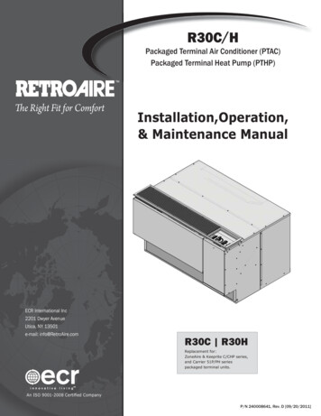
BHEL-HPVP,VISAKHAPATNAMTECHNICAL SPECIFICATION OF 500KVA COMPACT SUBSTATION &RMURef no: WE-29082020-0111.Typical SLD’s(A) Typical SLD of 500KVA CSS::Page 15 of 31
BHEL-HPVP,VISAKHAPATNAMTECHNICAL SPECIFICATION OF 500KVA COMPACT SUBSTATION &RMURef no: WE-29082020-01Page 16 of 31
BHEL-HPVP,VISAKHAPATNAMTECHNICAL SPECIFICATION OF 500KVA COMPACT SUBSTATION &RMURef no:
High Voltage Low Voltage Pre-Fabricated Substation IEC:61330/62271-202 High Voltage Switches IEC 60265 Metal Enclosed High Voltage Switchgear IEC 60298/62271-200 High Voltage Switchgear IEC 60694/62271-100 Low Voltage Switchgear and Control gear IEC 60439/60947 Power Transformers IEC 60076 3. SCOPE & SPECIFIC REQUIREMENTS