Transcription
Dell SC200/SC220Storage EnclosuresGetting StartedWith Your SystemRegulatory Model E03JRegulatory Model E04J
Notes, Cautions, and WarningsNOTE: A NOTE indicates important information that helps you makebetter use of your Storage Center.CAUTION: A CAUTION indicates potential damage to hardware or loss ofdata if instructions are not followed.WARNING: A WARNING indicates a potential for property damage,personal injury, or death.Contacting Dell Technical Support ServicesFor technical support, go to support.dell.com/compellent/.Information in this document is subject to change without notice. 2012 Dell Inc. All rights reserved.Reproduction of these materials in any manner whatsoever without the written permissionof Dell Inc. is strictly forbidden.Trademarks used in this text: Dell and the DELL logo.Other trademarks and trade names may be used in this document to refer to either the entitiesclaiming the marks and names or their products. Dell Inc. disclaims any proprietary interestin trademarks and trade names other than its own.Regulatory Model Series E03JRegulatory Model Series E04JSeptember 2012P/N 1C9X5Rev. A00
Installation and ConfigurationWARNING: Before performing the following procedure, review the safetyinstructions that came with all Storage Center components.Unpacking the SystemNOTE: Unpacking, installing, and deploying your Storage Center may bedone only by a certified service technician.Before you begin, make sure the site where you intend to set up and usethe Storage Center has the following: Standard power from an independent source or a rack powerdistribution unit with a UPS. Storage Center with the latest firmware, BIOS, and drivers. Contactyour supplier for the correct software versions.Installation OverviewThe installation process follows the general steps below. For detailedinformation, refer to vendor documentation supplied with the equipment.CAUTION: If installed in a closed or multi-unit rack assembly, theoperating ambient temperature of the rack environment may be greaterthan room ambient temperature. Therefore, consideration should be givento installing the equipment in an environment compatible with the maximumambient temperature (Tma) specified by the manufacturer. For moreinformation, see "Technical Specifications" on page 8.1 Assemble the rails following the safety instructions and the rackinstallation instructions provided with your system.2 Install network switches, as applicable.3 Unpack the Storage Center controllers.4 Unpack and install the IO cards into the Storage Center controllers.5 Install the Storage Center controllers into the rack.6 Unpack the enclosures.7 Install the enclosures into the rack.Getting Started With Your System3
Always load the rack from the bottom up for weight stability. You can allow room for expansion if you have fewer than themaximum number of enclosures.8 Unwrap and insert each drive into the enclosure one at a time. Protect the drive from static discharge. Handle drives by the edges of the frame.CAUTION: If the enclosure system operates for more than a few minuteswith missing drives, the enclosure can overheat, causing power failure anddata loss. Such use may invalidate the warranty.4Getting Started With Your System
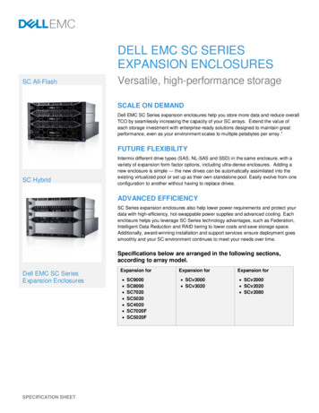
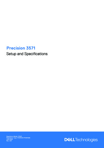
Connecting the Power Cables1 Ensure that the power switch is in the OFF position before connectingthe power cables.2 Connect the enclosure power cables to the rack power.Securing the Power Cables1 Bend the power cables as shown in the illustration and secure thecables firmly to the bracket using the strap provided.Getting Started With Your System5
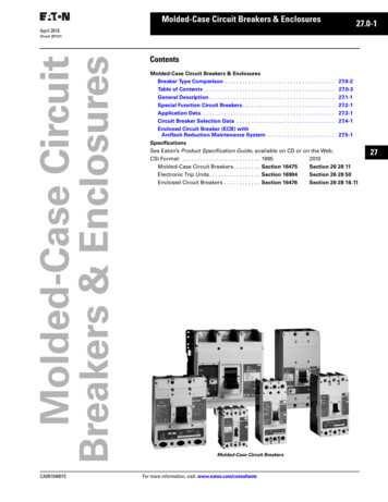
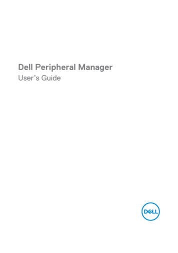
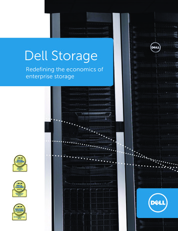
2 Plug the other end of the power cables into a grounded electricaloutlet or a separate power source such as an uninterrupted powersupply (UPS) or a power distribution unit (PDU).Location of Power ButtonNOTE: Do not power up the enclosure until all Storage Centercomponents are racked and cabled.Installing the Optional Bezel 6Install the bezel (optional).Getting Started With Your System
Other Information You May NeedWARNING: See the safety and regulatory information that shipped withyour Storage Center components. Warranty information may be includedwithin this document or as a separate document. The rack documentation included with your rack solution describeshow to install your system into a rack. The Storage Center Connectivity Guide provides information aboutcabling all Storage Center hardware components. The Storage Center System Setup Guide provides instructions forconfiguring a new Storage Center using the System Manager SetupWizard. The Storage Center System Manager Administrator’s Guide describeshow to manage a Storage Center.Getting Started With Your System7
NOM Information (Mexico Only)The following information is provided on the device described in thisdocument in compliance with the requirements of the official Mexicanstandards (NOM):Importer:Model number:Supply voltage:Frequency:Current consumption:Dell Inc. de México, S.A. de C.VPaseo de la Reforma 2620-11 PisoCol. Lomas Atlas11950 México, D.F.E04J100–240 V CA50/60 Hz8.6 ATechnical SpecificationsDrivesSAS hard drivesSC200: Up to 12 3.5-inch SAShot-swappable hard drives (6.0 Gbps)SC220: Up to 24 2.5-inch SAShot-swappable hard drives (6.0 Gbps)Enclosure Management Modules (EMMs)EMMsTwo hot-swappable modules withtemperature sensors and an audio alarmConnectivityConfigurationsStorage Center supports up to 168 drivesin each redundant-path enclosure chainEach SC8000 controller supports up to 6enclosure chainsRedundant Array of Independent Disks (RAID)Controller8Dell Compellent SC8000Getting Started With Your System
Redundant Array of Independent Disks (RAID) (continued)ManagementRAID management using Storage CenterSystem Manager version 6.2 or laterBack-Plane BoardConnectors SC200: 12 SAS hard-drive connectors SC220: 24 SAS hard-drive connectors Two power supply/cooling fanmodule connectors Two sets of EMM connectors One control panel connector for frontLEDsSensorsTwo temperature sensorsBack-Panel Connectors (per EMM)SAS connectorsSAS A and B connectors for connection tothe controller and for expansion to anadditional enclosureNOTE: SAS connectors areSFF-8086/SFF-8088 compliantSerial connectorOne 6-pin UART mini-DIN connectorNOTE: For engineering use onlyLED IndicatorsFront panel One two-color LED indicator forsystem status One single-color LED indicators forpower statusHard-drive carrier One single-color activity LED One two-color LED status indicatorper driveEMMThree two-color LED status indicators,one each for the two EMM SAS ports andone for the EMM statusGetting Started With Your System9
LED Indicators (continued)Power supply/cooling fanThree LED status indicators for powersupply status, power supply/cooling fanfault status, and AC statusPower SuppliesAC power supply (per power supply)Wattage700 WVoltage100–240 VAC (8.6 A–4.3 A)Heat dissipationSC200: 191-147 WSC220: 133-114 WMaximum inrush currentUnder typical line conditions and over theentire system ambient operating range,the inrush current may reach 55 A perpower supply for 10 ms or lessAvailable Hard Drive Power (Per Slot)Supported hard drive powerconsumption (continuous)SC200: Up to 1.16 A at 5 V,Up to 1.6 A at 12 VSC220: Up to 1.2 A at 5 V,Up to 0.5 A at 12 VEMM Power (Per Slot)Maximum power consumed byEMMSC200: 11 W at 12 VMaximum available power100 W at 12 VMaximum available power1 W at 5 V (standby)SC220: 14 W at 12 VPhysicalHeight8.68 cm (3.41 inches)Width44.63 cm (17.57 inches)DepthSC200: 59.4 cm (23.4 inches)SC220: 54.1 cm (21.3 inches)10Getting Started With Your System
Physical (continued)Weight (maximum configuration)SC200: 29.2 kg (64 lb)SC220: 24 kg (53 lb)Weight (empty)SC200: 8.84 kg (19.5 lb)SC220: 8.61 kg (19 lb)EnvironmentalNOTE: For additional information about environmental measurements forspecific system configurations, see dell.com/environmental datasheets.TemperatureOperating5 to 40 C (41 to 104 F) with a maximumtemperature gradation of 10 C per hourNOTE: For altitudes above 2950 feet,the maximum operating temperatureis derated 1ºF/550 ft.Storage–40 to 65 C (–40 to 149 F) witha maximum temperature gradationof 20 C per hourRelative humidityOperating20% to 80% (noncondensing) witha maximum humidity gradationof 10% per hourStorage5% to 95% (noncondensing)Maximum vibrationOperating0.26 G at 5–350 Hz for 15 minStorage1.88 G at 10–500 Hz for 15 minMaximum shockOperatingHalf-sine shock 31G /- 5% with a pulseduration of 2.6ms /10% in operational orientations onlyGetting Started With Your System11
Environmental (continued)Storage Half-sine shock 71G /- 5% with a pulseduration of 2ms /- 10% (all sides) Square wave shock 27G with a velocitychange of 235 in/sec (all sides)AltitudeOperating–16 to 3048 m (–50 to 10,000 ft)NOTE: For altitudes above 2950 feet,the maximum operating temperature isderated 1ºF/550 ft.Storage–16 to 10,600 m (–50 to 35,000 ft)Airborne Contaminant LevelClass12G2 or lower as defined by ISA-S71.041985Getting Started With Your System
w w w. d e l l . c o m s u p p o r t . d e ll . c o m
Getting Started With Your System 5 Connecting the Power Cables 1 Ensure that the power switch is in the OFF position before connecting the power cables. 2 Connect the enclosure power cables to the rack power. Securing the Power Cables 1 Bend the power cables as shown in the illustration and secure the cables firmly to the bracket using the strap provided.