Transcription
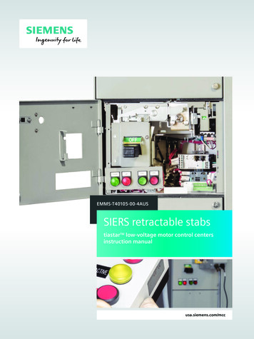
tiastar TM Motor Control CenterCatalog and Application GuideGame Changing Innovationusa.siemens.com/mccAnswers for industry.
Table of ContentsIntroductiontiastar MCCProduct Features and Benefitstiastar Arc Resistant MCCKey Innovations of Arc Resistant Designtiastar Smart MCC4681012General InformationCodes and StandardsEstimated MCC Shipping WeightNEMA Wire Classes and TypesMCC Heat DissipationAltitude Ratings1415161820Structure and BussingNEMA Enclosure TypesPaint and MCC FinishStructure Design and OptionsBus Selection and OptionsWireways2122232629Mains, Feeders, andIncoming DevicesIncoming Line Termination & Cable SpaceMain Lug Only (MLO)Main Circuit Breaker (MCB)Main Disconnect Switch (MDS)FeedersBus Splice & Bus DuctTPS3 Surge Protective Devices (SPD)30323436384244UnitsPlug-in Unit FeaturesCombination StartersCompact High Density (HD)Combination StartersReduced Voltage Soft-Starter (RVSS) Units46485657
Variable Frequency Drive (VFD) UnitsMicromasterSINAMICS G120CSINAMICS G120Unit Options OverloadSIMOCODETerminal BlocksWiring SpecificationsPilot DevicesControl Transformer SizesHandle Auxiliary SwitchNameplateProgrammable Logic Controller (PLCs) UnitsMetering UnitsPanelboard and Transformer UnitsHigh Resistance Ground Unit Option616770767779818284848586878990Standard MCC Catalog ItemsFeeder Circuit Breaker (FCB)Vertical Catalog SectionsBlank, Panel, MLO and MCBVertical Catalog SectionsFeeder Circuit Breaker (FCB)Catalog UnitsFull Voltage Non-Reversing (FVNR)Catalog UnitsCommon Modification KitsOther Modification Kits929598101104105AppendixDrawings and DimensionsMotor Circuit Protector (MCP) SelectionBreaker Trip SettingsBreaker SelectionFuse Selection/UL StandardFuse ClassificationsHeater TablesTypical SchematicAftermarketTypical SpecificationsGeneral MCC or Arc Resistant MCCSmart MCCMCC Training106118119120121124128136137142149For instruction manuals and instructional videos please see the SiemensMotor Control Center website usa.siemens.com/mcc
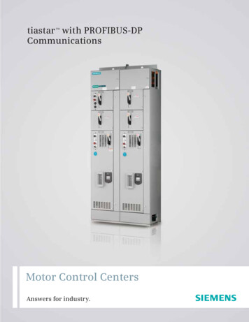
IntroductionStandard MCCtiastar MCCMotor Control Centers (MCC) have come a long way since they were introduced in 1937as a way to save floor space by placing several starters in a single cabinet. Ideally, thebest of the best must also save installation time and money.Siemens has an installed base of Motor Control Centers dating back to 1964. OurSiemens tiastar MCCs are designed as self-contained modular units which meets UL andNEMA standards. They come with rear-mounted, self-aligning copper stabs that firmlygrasp onto the bus. Brackets guide the placement of units, further assuring positiveengagement with the bus. From 22mm to 30mm pilot devices, from direct starters toworld-class drives, the Siemens tiastar MCC has many features and options to meet yourspecific needs.n UL 845 Labeling as applicablen CSA C22.2 No. 254-05 Labeling as applicable when specifiedn Heavy-Duty Construction with up to 100kA Bus Bracingn 600V 50/60 Hzn NEMA Wiringn Plug-In Units (up to Size 5 Starters)n Door/Unit Mounted Pilot Device Paneln High Density Compact Units available to reduce footprint4
IntroductionTechnical Specifications Summary – tiastar MCCBus and Electrical RatingsHorizontal Bus Ratings600A, 800A, 1200A, 1600A, 2000A,2500A1Horizontal Bus MaterialCopper with tin or silver plating,or Aluminum2 with tin platingVertical Bus Ratings300A, 600A, 800AVertical Bus OptionsIsolated (standard)Insulated and isolated (optional)Auto Shutters (optional)Bus Bracing42K AIC, 65K AIC, 100K AICMax MCC Voltage Rating600 VFor further bus information please see the "Bus Selection and Options" sectionEnclosureEnclosure TypeNEMA 1 (standard), NEMA 1A,NEMA 2, NEMA 12,NEMA 3R (non walk-in)Back-to-Back OptionAvailableDimensionsSection Depth15”, 20” , 21” (back-to-back),31” (double deep), 41” (double deep)Section Width20”, 24”, 30”, 40”, 50”, 60”1 NEMA 1 only and requires forced ventilation2 for 600-1200A, 65KA, 65 C5
IntroductionStandard MCCProduct Features & BenefitsSiemens tiastar Motor Control Centers (MCC) are composed of a number of verticalsections bolted together which allows for future addition of MCC vertical sections in casethe customer requires expansion.BenefitsEasy accessibilityfor fastermaintenance6FeatureEntire horizontal busassembly is in top12” of the vertical sectionEasy visualinspection ofhorizontal busClear Lexan horizontalwireway barrierEase of installationand movement ofplug-in unitsPlug-in units withintegratedracking handles
IntroductionBenefitsFeaturePrevents arcingfaults frompropagatingIsolated and insulatedvertical bus assembly(Optional)Improved serviceaccess to save timeDual location pilotdevice panelClearly indicatesequipment status(ON, TRIP, OFF)Industry’s best unitoperating handle7
IntroductiontiastarArc Resistant MCCThe Type 2A Arc Resistant low voltage motor control center is a new product offeringthat was tested in accordance to IEEE C37.20.7, which contains and channels internalarcing fault incident energy. It provides an additional degree of protection to thepersonnel performing normal operating duties in close proximity to the equipment whilethe equipment is operating under normal conditions. Type 2A accessibility means theMCC protects the operator in front, back and sides of the equipment.The Arc Resistant MCC is a state-of-art overarching technology. This means one can getan Arc Resistant MCC that can have various Smart components with communications,and/or High Density compact units.8
IntroductionTechnical Specifications Summary – tiastar Arc Resistant MCCBus and Electrical RatingsMaximum Horizontal Bus1600 AMaximum Vertical Bus800 AMaximum Short CircuitWithstand Rating65KAArc Flash Duration50ms (3 cycles)Maximum Voltage Rating600VACHorizontal Bus DetailsCopper OnlyIncomingMLO,MCB/MDS 1600 A max,splice to existing1EnclosureEnclosure TypeNEMA 1 and 1AHigh Density Units OptionAvailableVFD, RVSS UnitsAvailableDouble Deep OptionAvailableDimensionsModified Pull Box Height12” Minimum (standard),18” and 24” (optional)Section Depth20”Section Width20” or 30”Total MCC Height102” Minimum2Room Requirements112” Minimum Ceiling Height(Total MCC Height 10”)38” Minimum Aisle1 The Arc Resistant MCC should not be spliced to a Non-Arc Resistant MCC.2 If the mounting channels are surface mounted then the minimum height is 103” (90” MCC height 1” mountingchannels 12” modified pull box). Also, note that the total MCC height will increase if standard modified pull box isnot selected.9
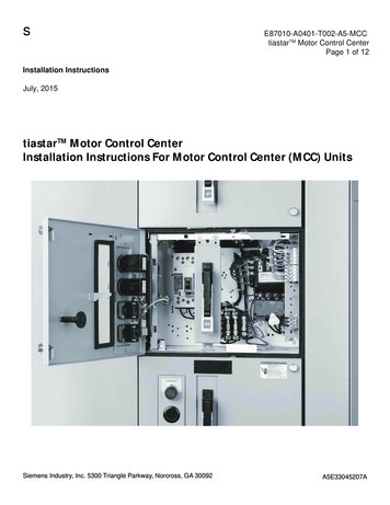
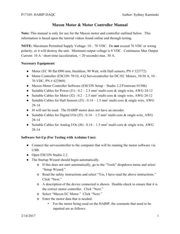
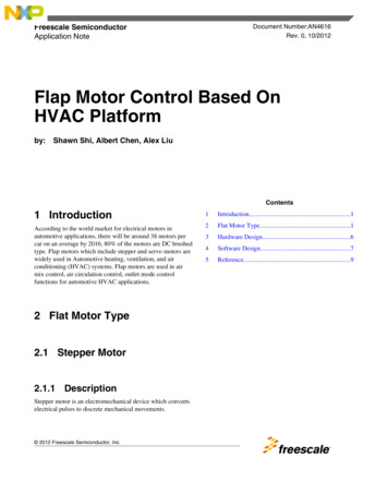
IntroductionArc Resistant MCCKey Innovations and Benefitsof Arc Resistant DesignREINFORCED DOORSReinforced cabinet ensure the equipmentcan withstand and contain pressure frominternal arcing faults.AUTOMATIC SHUTTERSThe barrier automatically opens andcloses to allow insertion or removalof units. It isolates the vertical bus toprevent inadvertent contact loweringthe risk to personnel.OpenBOLTED WIREWAYThe wireway is bolted to ensureintegrity of the MCC wireway issustained during an arc flash incident.ClosedINSULATED BUS BARIsolates energized components,prevents accidental contact, and keepsarcing faults from propagating.INTERNAL VENTING SYSTEMThe vertical wireway is perforatedwith holes that channel the gasses tothe back and out the top of the MCC.Figure 1. Arc Resistant MCC10
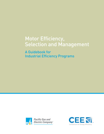
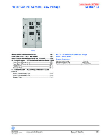
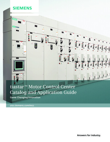
IntroductionDEFLECTORSThe protection plate will allow MCCs tohave vented doors, but will reduce thedirect launching of arc flash by-products.MODIFIED PULL-BOXWITH PRESSURE FLAPThe arc flash by-products will be prevented fromescaping due to the wire mesh, while the pressureflap will allow pressure release.Figure 2. Closed Door View - Arc Resistant MCCDynamic Arc Flash Sentry (DAS)To complement the Arc Resistant MCC, the Dynamic Arc FlashSentry (DAS) option is available. Dynamic Arc Flash Sentry(DAS) is a patented feature available in both Siemens MCCsand type WL Low Voltage Switchgear. The unique dual tripsetting technology reduces the energy available in an arcflash event.For more information, please see the Dynamic Arc FlashReduction System and its Application in Motor ControlCenters white paper at www.usa.siemens.com/mcc11
IntroductionSmart MCCtiastar Smart MCCA Smart MCC is a networked NEMA compliant MCC that can communicate. Itincorporates intelligent devices at the unit level to control and monitor motoroperation, energy consumption, and power quality. It rapidly communicates with aPLC or process control system via a data network.Smart MCC ComponentsSmart MCC is internally interconnected using PROFIBUS DP which incorporatesintelligent devices such as SIMOCODE pro C and V motor management systems, SIRIUS3RW44 soft starters, SIMATIC PLCs, Siemens VFDs, and other smart components.Major Benefitsn Reduces Wiring Connectionsn Reduces Costn Improves Operational Diagnosticsn Simplifies Installation and Troubleshooting12
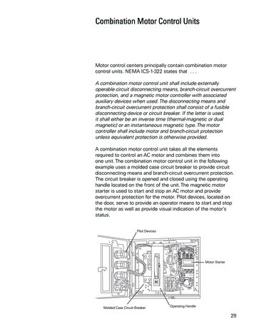
Introductiontiastar Smart MCC Network ArchitectureSiemens DistributedControl SystemPCS7Siemens ProgrammableLogic ControllersSIMATIC S7 PLCsThird PartyPLC or DCSSystemsPROFIBUS DPFigure 3. Example of a Smart MCC Network with PROFIBUSOptionsA Smart MCC has the option to externally talk to other networks such as DeviceNet,Modbus RTU, Modbus TCP/IP, EtherNet/IP, and PROFINET.VFD, RVSS UnitsAvailableHigh Density 6” Units OptionNot AvailableBack-to-Back OptionAvailableDouble Deep OptionAvailable13
General InformationCodes and StandardsSiemens tiastar MCCs are manufactured to American NationalStandards Institute (ANSI) / Underwriters Laboratories (UL) 845standard and contain the “UL Listed” label.Siemens tiastar MCCs complies with National ElectricalManufacturers Association (NEMA) ICS 18-2001.Siemens tiastar MCCs also complies with Canadian StandardsAssociation (CSA) C22.2 No. 254-05 standards.Siemens tiastar MCCs are American Bureau of Shipping (ABS)Type Approval Certificated.1SeismicCertificationSiemens tiastar Motor Control Centers are certified to CBC-2013Section 170A 12 and IBC 2012 Section 1705.12.OSHPDSiemens tiastar Motor Control Centers can also have Office ofStatewide Health Planning and Development Facilities (OSHPD)Special Seismic Certification Preapproval (OSP).1. Some restrictions may apply. Please contact factory for further details.14
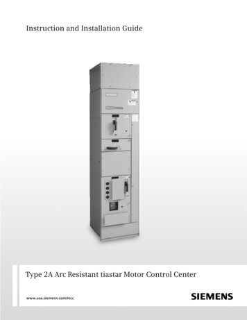
General InformationEstimated MCC Shipping WeightDimensions inInches (mm)WidthDepthTypeWeight per Sectionin lbs (Kg) forNEMA 1, 2, or 1220” (508)15” (381)Front Only550 (250)650 (295)20” (508)20” (508)Front Only650 (295)700 (318)30” (762)15” (381)Front Only700 (318)800 (363)30” (762)20” (508)Front Only850 (386)900 (409)20” (508)21” (533)Back-to-Back670 (304)N/A30” (762)21” (533)Back-to-Back880 (400)N/AWeight per Sectionin lbs (Kg) forNEMA 3RNote: MCC shipping split maximum is 80 inches (for example, four 20-inch wide vertical sections).When a motor control centeris made up of more than onevertical section, the sectionsare assembled together witha common top-frame andbottom-frame assembly. Forshipping, this assembly canconsist of a maximum of four20-inch wide vertical sections(80” maximum). Severalassemblies can be bolted andbussed together at theinstallation site to form acomplete lineup.Figure 4. Example of shipping splitWhen there are more than four sections orthe customer specifies a split between twovertical sections, a splice kit, must beinstalled to join the horizontal bus bars.Splice PlatesFigure 5. Splice plates15
General InformationNEMA Wire Classes and TypesSiemens MCCs are available as either Class I or Class II assemblies utilizing either Type A,Type B, or Type C wiring as defined in NEMA ICS18-2001. Below are the NEMA class andtype definitions:NEMA ClassesClass I — Independent UnitsClass I motor control centers shall consist of mechanical groupings of combinationmotor control units, feeder tap units, other units, and electrical devices arranged ina convenient assembly. The manufacturer shall furnish drawings that include:a. Overall dimensions of the motor control center, identification of units and theirlocation in the motor control center, locations of incoming line terminals,mounting dimensions, available conduit entrance areas, and the location ofthe master terminal board if required (Type C wiring only).b. Manufacturer’s standard diagrams for individual units and master terminalboards (Type C wiring only) consist of one or more drawing(s) that: Identify electrical devices Indicate electrical connections Indicate terminal numbering designationsNote: When a combination schematic and / or wiring diagram for a unit issupplied showing optional devices, the manufacturer shall provide informationto indicate which devices are actually furnished.Class II — Interconnected UnitsClass II motor control centers shall be the same as Class I motor control centers withthe addition of manufacturer furnished electrical interlocking and wiring betweenunits as specified in overall control system diagrams supplied by the purchaser. Inaddition to the drawings furnished for Class I motor control centers, themanufacturer shall furnish drawings that indicate factory interconnections withinthe motor control center.Class I-S and II-S — Motor Control Centers withCustom Drawing RequirementsClass I-S and II-S motor control centers shall be the same as Class I and II exceptcustom drawings shall be provided in lieu of standard drawings as specified by theuser.Examples of custom drawings are Special identifications for electrical devices Special terminal numbering designations Special sizes of drawingsThe drawings supplied by the manufacturer shall convey the same information asdrawings provided with Class I and II motor control centers, additionally modified asspecified by the user.16
NEMA TypesType AUser field wiring shall connect directly to deviceterminals internal to the unit and shall be provided onlyon Class I motor control centers.Figure 6.Class I,Type AWiringType BType B user field load wiring for combination motorcontrol units size 3 or smaller shall be designated asB-d or B-t, according to the following:B-d connects directly to the unit terminals, whichare located immediately adjacent and readilyaccessible to the vertical wireway.B-t connects directly to a load terminal block in, oradjacent to, the unit.Figure 7.Class I,Type B-dWiringType B user field load wiring for combination motorcontrol units larger than size 3, and for feeder tapunits, shall connect directly to unit device terminals.Type B user field control wiring shall connect directlyto unit terminal block(s) located in, or adjacent to,each combination motor control unit.Figure 8.Class I,Type B-tWiringType CUser field control wiring shall connect directly tomaster terminal blocks mounted at the top or bottomof those vertical sections that contain combinationmotor control units or control assemblies which shallbe factory wired to their master terminal blocks. Userfield load wiring for combination motor control units,size 3 or smaller, shall connect directly to masterterminal blocks mounted at the top or bottom ofvertical sections. Motor control unit load wiring shallbe factory wired to the master terminal blocks. Userfield load wiring for combination motor control unitslarger than size 3, and for feeder tap units, shallconnect directly to unit device terminals.Figure 9.Class I,Type CWiring17
General InformationMCC Heat DissipationThe purpose of this section is to allow thereader to approximate the heat output ofan MCC. This information is based onpower loss data collected for the majorheat producing components.square of the true current divided by thesquare of the rated current:i2 actuali2 maxPactual PmaxThe data presented here is based off themaximum rated current for eachcomponent. If the true loading current isknown, then the estimate can be improvedby multiplying the given power loss by theThe power losses can be multiplied by3.412 to convert them from Watts toBTU/hr.1. Combination Motor StartersMaximum Power Loss (3-Pole) 300849361720065001901746173872. CircuitBreakersimax[A]18Contactor3. LightingTransformersWatts Loss(3-pole)4. Reduced VoltageSoft erLoss 3X145954X3852325X8502706X10786303RW443RW403RW303
General InformationMCC Heat Dissipation5. Panel BoardsMaximum Power Loss (3-Pole) [W]Sizeimax[A]BusMainBreakerBranch 3800470192116961136. Variable Frequency DrivesThe power loss for a variable frequency drive is approximately 3.5% of the overall power:0.746W . 3.5%Power Loss (HP of Motor) .HPMaximum Power Loss (3-Pole) [W]Horizontal(20” Section)imax[A]AluminumVertical(72” 120721600852000662500104The data presented here is subject to change, without notice, owing to periodic updates and corrections. Pleasebe advised that several assumptions had to be made in order to generate this and, accordingly, no representationor warranty is given with regard to its accuracy or completeness of the information as the same has been included for general purposes only and that, it should not be relied upon for any specific purpose. Siemens industry,inc. Or its affiliates, officers, employees or agents are neither responsible nor liable for inaccuracies, errors oromissions, or for any loss, damage or expense, including, without limitation, any loss of profit, indirect, special,incidental or consequential loss / damages, arising out of this data.19
General InformationAltitude RatingsSiemens tiastarMotor ControlCenters aredesigned and builtto operate up to2000 meters abovesea level (6,600 ft)without anymodifications.Altitude (m)Motor control centers are often installed in applications exceeding 1000 meters (3300 ft)above sea level. Due to the lower air density and heat transfer capacity at elevatedaltitudes, the physical properties such as dielectric strength, load capacity of the motorcontrol centers, conductors and motors, as well as the tripping characteristics of thermalrelays may require modification to reflect these changes due to altitude. Paschen’s Lawdescribes the breakdown voltage of parallel plates in a gas, as a function of pressure andgap distance. In other words, at lower pressure (higher altitudes) it takes less voltage tocross a given distance increasing the chance for electrical arcs. To compensate for this, itis recommended that the operational voltage be de-rated for altitudes exceeding 2,000meters according to Paschen’s law. In addition, the rated thermal current should also bereduced because of the decreased thermal efficiency of lower density (high altitude) air.Siemens tiastar Motor Control Centers are designed and built to operate up to 2000meters above sea level (6,600 ft) without any modifications. Siemens MCC componentsare designed and manufactured to provide excellent insulation and arc flash protectionfor bus components, in addition to having high thermal efficiency. Using creative designand engineering, Siemens MCC’s can operate safely and reliably at altitudes up to 5,000meters above sea level. 20002001-3000De-RatingVoltageCurrentVoltageMotor Control CenterStd. Aluminum & Copper65 C rise horizontal urrentRequires enhanced Copper50 C rise horizontal busMotor Control Center(MCC Bus & %460V78%460V70%MM440 frame (FXGX)100%100%90%90%77%85%MM440 frame (A-F)100%90%90%85%77%80%WL Breakers600V100%480V97%480V94%445V91%G120 (FSA.FMF) PM240100%92%88%86%77%80%G120 (FSGX) PM240100%100%88%92%77%85%Starters1Soft StartersDrivesThe data presented here is subject to change, without notice, owing to periodic updates and corrections. Contact factory for latest information.1 ESP200 and/or the 3RB20 overloads are included in the ratings. For SIMOCODE, there is no de-rating required for 2000 meters. Usage is limitedfor applications above 2000 meters depending on ambient temperature. For more detail, please see the SIMOCODE Pro System Manual.20
Structure & BussingNEMA Enclosure TypesEnclosureTypesIndoor orOutdoorNEMA 1IndoorDescriptionThis enclosure is primarily to prevent accidental contact by personnel with the enclosedequipment and for protection against falling dirt. NEMA 12 reset and handlemechanisms are standard for all enclosures.This enclosure has the same use as NEMA 1 except the front of the enclosure isgasketed.NEMA 1AIndoorThe parts that are gasketed include: Unit separator angles, Right hand side of front ofunits, Bottom horizontal cross ties, Lip on top plate, Handle mechanism, and Bottomhorizontal wireway cover plate. The whole front of structure is gasketed, except thehinged side of door.This design is NEMA 1A front with a drip shield mounted on top of the enclosure.NEMA 2IndoorThis enclosure is to protect equipment against falling noncorrosive liquids and dirt. Itprevents the entrance of dripping liquid at a higher level than the lowest live part withinthe enclosure. The drip shield completely covers the top and extends 3” over the frontand 1 1/2” over the sides of the basic structure. On front-only MCC’s, the drip shield isflush to the rear. The drip shield is angled from front to rear and not flush with the topof the MCC. The drip shield mounts on the top of the structure.This enclosure is intended for indoor use in areas where fibers, lint, dust, dirt, and lightsplashing are prevalent. The NEMA Type 12 enclosure will provide a greater degree ofprotection than a NEMA 1A enclosure.NEMA 12NEMA 3RIndoorOutdoor(Nonwalk-in)The following additional parts are gasketed: hinged side of doors, pilot device panel,top plates, wireway end-covers, and rear plates. Because of the divider side sheetassemblies, there is no gap between sections, allowing for much greater dust resistance.In addition, interconnection holes in the side sheet assemblies are sealed. Bottom platesare included when NEMA 12 is specified.This enclosure will prevent entrance of rain at a level higher than the lowest live part.The enclosure has provision for locking and drainage. This NEMA 3R enclosure entirelysurrounds the motor control center for outdoor operation. Each non walk-in enclosurehas a floor and a slanted roof. All doors are louvered and screened to promote aircirculation and keep out pests. Motor control units can be racked in positive stop/testposition with the outer enclosure doors closed.Rigid steel construction permits use from two sections up to any reasonable number ofsections. Stainless steel hinge pins and door stops are standard. Pressure SensitiveAdhesive (PSA) Closed Cell Sponge Rubber door gasket forms a tight seal to keep theelements out. Space heaters, fluorescent lights, fans, filters, blowers, and convenienceoutlets are available as options. NEMA 3R enclosures are designed to accommodatebottom cable entry and exit only. The enclosures are not intended to provide protectionagainst conditions such as dust, snow, or sleet (ice).Attention: Variable Frequency Drives require special consideration, see units chapter VFD section for further details.Figure 10.NEMA 3Renclosure21
Structure & BussingPaint and MCC FinishThe motor control finish is anelectrostatically applied TGIC-free polyesterpowder, applied both manually andautomatically in an environmentallycontrolled clean room, cured at 400 Ffor 20 minutes. All painted parts undergoa five-stage preparation process thatincludes an alkaline wash, water rinse,iron phosphate wash, water rinse and anon-chrome sealer. The minimum filmthickness on external surfaces is 2.0 Milsand the finish passes a 600-hour salt spraytest per ASTM B117-94 definitions.ANSI 61 Light Gray is the standard exteriorcolor. Unit backplates and the rear of thevertical wireway are painted white forimproved visibility.Custom color MCC’s are available.22
Structure Design and OptionsSectionsHeavy 14 gauge steel side sheet assembliesare used for supporting the structurewithout additional bracing. The front ofeach side frame has a 180 bend to provideadditional rigidity and a smooth edge.Cross channels tie the side frames together.A common sheet is used to provideisolation between adjacent sections. Ashipping split will have two outer sidesheet assemblies and an inside divider sidesheet assembly between sections.Mounting SillsFull-length mounting sills are standard foreach shipping split. The sills are 3” wide by1 1/8” high and constructed of 7 gaugesteel. They have four holes per section foruse with 1/2” (max.) anchor bolts. The sillsadd additional structural rigidity. Themounting sills are an integral part of thestructure and should not be removed.Structural PartsDivider Sheets14 ga.Side Sheets14 ga.Center Bottom Cross Ties12 ga.Rear-Channel (FO)13 ga.Channel Sills7 ga.Center-Top Channel13 ga.Vertical Bus Mounting Angles14 ga.Lifting Angles7 ga.Rear Covers16 ga.Top Plates13 ga.End Covers16 ga.Separator Angles12 ga.Shelf Brackets10 ga.Unit PartsTop and Bottom Unit Barriers14 ga.Back Pan13 ga.14 ga.Side Barrier Plate18 ga.Angles14 ga.Doors13 ga.14 ga.Note: Arc Resistant MCC metal thickness values will be different on some parts.23
Structure & BussingStructure Design and OptionsLifting AngleA 7 gauge lifting angle is supplied withevery shipping split regardless of length.The lifting angles are mounted atop theMCC structure.Side SheetsSide sheet assemblies on 20” deep unitsprovide a 40.5 square inch wirewayopening at the top and a 46 square inchwireway opening at the bottom tofacilitate routing wires through thehorizontal wireways between adjoiningsections. 15” deep units provide a 40.5square inch wireway opening at the topand a 30 square inch wireway opening atthe bottom.Figure 11. Vertical Section dimensions24
Back-to-Back and Double DeepMCC OptionsUsually MCCs are front-mounted. However,for the customers who want to save spaceand cost, we offer our standard 21“ deepback-to-back MCC design. We are the onlymanufacturer in the market that offers 21”deep back-to-back design with commonhorizontal and vertical buses.For customers that would like to haveback-to-back configuration but withseparate horizontal and separate verticalbusses for both the front and rear, doubledeep MCCs are available with depths of31" and 41".Pull Box (Top Hat) OptionsPull boxes are generally used to provideincreased conduit mounting space andadditional cable bending space forincoming main feeds instead of bus ductconnections. This type of pull box assemblyis referred to as a “top hat.” Top hats areshipped 12”, 18”, or 24” high; 20” or 30”wide; 15" or 20" deep for customer fieldinstallation on top of MCCs.Each pull box has an open bottom withOptionalPullinBoxmounting holespunchedits front and(TopHat)rear flange. After removing the top liftingangle and front conduit cover from theMCC, the pull box can be bolted to pretapped holes. The pull box has front, top,12”, 18”, 24”and back removable covers.Stab-on ConnectionsVerticalBusStabFront-Mounted UnitFront UnitRear UnitBack-to-Back Mounted Units21”Back-to-BackMountingFigure 12. Back-to-Back ConfigurationFigure 13. Pull Box OptionSpecial Structures30”, 40”, 50”, and 60” wide sections areavailable for larger units such as largehorsepower VFD, RVSS or special panelsthat may require it. 30” and widerstructures may have horizontal bus, but arenot supplied with vertical bus. 30” widestructures are available in 15” or 20” deepdesign and line up with standard 20” widesections. 30” sections have full-widthdoors, while wider sections have twointerposing doors. Dimensions for otherspecial equipment such as transferswitches, NEMA 3R outdoor enclosures, orspecial service entrance enclosures will beprovided on request.25
Structure & BussingBus Selection and OptionsFor additional strength, the horizontal bus, vertical bus, bus support angles, and busbracing insulators form one unified assembly.Horizontal BusThe horizontal bus is a means of tappingpower for distribution to the various unitswithin a section. Siemens tiastar MCC’shorizontal bus is always located on the topof the vertical section and never locatedbehind unit space, allowing for easymaintenance and serviceability.Horizontal Bus SpecificationsHorizontal BusCurrent Ratings600A, 800A, 1200A, 1600A, 2000A, 2500A1 onlyHorizontal BusMaterial OptionsCopper with tin or silver plating,or Aluminum2 with tin platingVertical BusThe standard vertical bus is tin-plated copper 3/8” thick with rounded edges. The edgeson the vertical bus are rounded to assist in units stabbing onto the bus.Vertical Bus SpecificationsVertical BusCurrent Ratings300A, 600A, 800AVertical BusOptionsIsolated (standard for 42kA or 65kA bus bracing)Insulated and isolated (optional for 42kA or 65kA busbracing; standard for 100kA bus bracing and back-to-back)Auto Shutters (standard for the Arc Resistant MCC; optionalfor all other configurations)Stab PlatingTin (standard)Silver (optional)Bus Bracing42K AIC, 65K AIC, 100K AIC1 NEMA 1 only2 for 600-1200A, 65KA26
Structure & BussingVertical Bus (cont)Vertical buses are available in two designs:1) Isolated – Isolated vertical bus design isgrounded sheet steel with stabopenings and is the standard for frontonly structures with 42kA or 65kA busbracing.The vertical bus bars in thisdesign are not physically insulatedphase-to-phase.2) Insulated and Isolated – An optionalinsulated and isolated vertical busdesign which prevents arcing faultsfrom propagating is available for frontonly 42kA and 65kA bus bracing. Theisolated and insulated vertical busdesign is standard for 100kA busbracing and all back-to-back structures.Figure 14. Isolated vertical busFigure 15. Insulated and Isolated Vertical BusAuto Sh
Class I motor control centers shall consist of mechanical groupings of combination motor control units, feeder tap units, other units, and electrical devices arranged in a convenient assembly. The manufacturer shall furnish drawings that include: a. Overall dimensions of the motor control center, identification of units and their