Transcription
Instruction and Installation GuideType 2A Arc Resistant tiastar Motor Control Centerwww.usa.siemens.com/mcc
DANGERHazardous voltage.Will cause death orserious injury.Keep out.Qualified personnel only.Disconnect and lock off allpower before working onthis equipment.IMPORTANTThe information contained herein is general in nature and not intended for specific application purposes. It does not relieve theuser of responsibility to use sound practices in application, installation, operation, and maintenance of the equipment purchased.Siemens reserves the right to make changes in the specifications shown herein or to make improvements at any time without noticeor obligations. Should a conflict arise between the general information contained in this publication and the contents of drawingsor supplementary material or both, the latter shall take precedence.NOTEThese instructions do not purport to cover all details or variations in equipment, nor to provide for every possible contingency to bemet in connection with installation, operation, or maintenance. Should further information be desired or should particular problemsarise which are not covered sufficiently for the purchaser’s purposes, the matter should be referred to the local Siemens sales office. Thecontents of this instruction manual should not become part of or modify any prior or existing agreement, commitment, or relationship.The sales contract contains the entire obligation of Siemens Industry, Inc. The warranty contained in the contract between the parties isthe sole warranty of Siemens Industry, Inc. Any statements contained herein do not create new warranties or modify theexisting warranty.
E87010-A0098-T004-A5-MCCTable of contentsIntroduction and safetyIntroductionQualified personSignal wordsWorking on equipmentField service operation44444General descriptionIntroductionScopeGeneral description555Special FeaturesMotor Control Center – rearMotor Control Center – front30” - 60” unit compartment666Ins tallationMCC dimensions, room requirements and other considerationsExpansion chamber installation78Plenum/DuctDesign guidelinesDrawings911
Type 2A Arc Resistant tiastar Motor Control CenterIntroduction and safetyIntroductionType 2A Arc Resistant tiastar Motor Control Center is designed tomeet all applicable UL, ANSI, NEMA and IEEE standards. It isdesigned and performance tested to IEEE Std C37.20.7-2007 toprovide an additional degree of protection from internal arc faults.Successful application and operation of this equipment dependsas much upon proper installation and maintenance by the useras it does upon the careful design and construction by Siemens.The purpose of this Instruction Manual is to assist the user indeveloping safe and efficient procedures for the installation,maintenance and use of the equipment. This Instruction Manualacts a supplement to CCIM-TIAST-1115 tiastar Motor ControlCenter Instruction Guide.Application of Arc Resistant tiastar Motor Control Center meetingthe requirements of IEEE Std C37.20.7-2007 does not eliminatethe requirements of Personal Protection Equipment (PPE).Contact the nearest Siemens representative if any additionalinformation is desired.DANGERHazardous voltage.Will cause death orserious injury.Keep out.Qualified personnel only.Disconnect and lock off all powerbefore working on this equipment.Qualified personFor the purpose of this manual and product labels, a QualifiedPerson is one who is familiar with the installation, constructionand operation of the equipment and the hazards involved. Inaddition, this person has the following qualifications: Training and authorization to energize, de-energize, clear,ground and tag circuits and equipment in accordance withestablished safety practices. Training in the proper care and use of protective equipmentsuch as rubber gloves, hard hat, safety glasses, face shields,flash clothing, etc., in accordance with establishedsafety procedures. Training in rendering first aid.4Signal wordsThe signal words “Danger,” “Warning” and “Caution” used in thismanual indicate the degree of hazard that may be encounteredby the user. These words are defined as:Danger – Indicates an imminently hazardous situation which ifnot avoided, will result in death or serious injury.Warning – Indicates a potentially hazardous situation which, ifnot avoided, could result in death or serious injury.Caution – Indicates a potentially hazardous situation which, ifnot avoided, may result in minor or moderate injury.Working on equipmentBefore performing work user personnel must adhere to the following.1. Disconnect and lockout incoming power and control voltagesources before beginning work on this or any otherelectrical equipment.2. Check all power and control circuit terminals with a voltmeterto make certain that the equipment is totally de-energized.3. Ensure that only Qualified Personnel be instructed and authorizedto use the defeater mechanism to gain access to a de-energizedcompartment.4. Never attempt to withdraw unit or disconnect any terminationswhen the defeater mechanism has been used to open thecompartment door.5. If any unit is removed from a MCC section, replace that unit doorwith a blank “screw down” cover to maintain Arc Resistant ratings.Field service operationSiemens can provide the following support services for tiastarMotor Control Centers.Call 1-800-241-4453 to obtain additional information and schedulean appointment. Start-up and commissioning Component and system testing Maintenance (scheduled and preventative) Repair and refurbishing On-site operational training
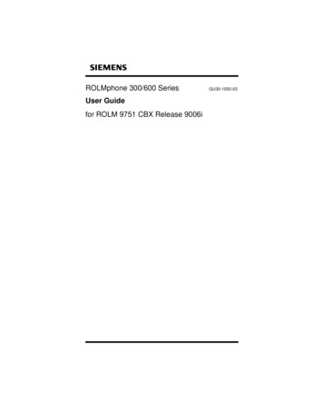
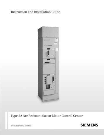
Type 2A Arc Resistant tiastar Motor Control CenterGeneral descriptionScopeThese instructions cover the installation and maintenance ofSiemens Type 2A arc resistant tiastar Motor Control Center.A typical Type 2A arc resistant tiastar Motor Control Center isshown in Figure 1.Instruction and installation details of standard motor controlcenters have already been discussed in CCIM-TIAST-1115 tiastarMotor Control Center Instruction Guide. This manual discussesthe special features and maintenance associated with arcresistant motor control centers.This document also provides general guidelines on theconfiguration, sizing, fabrication and assembly of a plenumsystem for Siemens arc resistant MCCs. Detailed dimensionedprints have been included for some critical components of theassembly, however it is the responsibility of the end user tofollow these guidelines for the manufacture and assembly of theremaining components for assuring safe and effect functionalityof the plenum.Figure 1. Front view of arc resistant tiastar Motor Control CenterIntroductionSiemens Type 2A arc resistant tiastar Motor Control Center isdesigned to provide an additional degree of protection forpersonnel performing normal operating duties in proximityto the energized equipment. Such duties include opening orclosing breakers, reading of instruments, or other such activitiesthat do not require the opening of doors or removal of covers.It is designed and performance tested to IEEE std C37.20.7 toprovide an additional degree of protection from internal arc faults.Plenum system is an assembly of parts/sub-assemblies to beused with Siemens arc resistant MCC, which is designed totransfer the products of an Arc Flash (smoke, particulate matter,heat, etc.) away from the immediate vicinity of the MCC whensuch an incident occurs. This system carries these products andexhausts them to a safer location- usually outside of the room inwhich the MCC is located. Thus using plenum system gives anadded degree of protection to personnel and other equipmentaround the gear which has been involved in the Arc Flash incident.General DescriptionType 2A arc resistant tiastar Motor Control Center is an assemblyof an indoor enclosure with a horizontal bus system withinsulating boots at the end sections, removable rear coverssecured to the enclosure with U-nuts, and screwed down wire waydoors.An expansion chamber (min 12” high) is required for each arcresistant MCC section.A minimum 38 inch clear aisle space must be maintained in frontof the motor control center. If accessible space is used on the sidesor rear of the motor control center provide a minimum 38 inches.A 112 inch minimum ceiling height must be maintained for properfunctioning of arc resistant motor control center.The arc resistant ratings are listed on the motor control centerrating label. Ratings are given for:1. Accessibility type2. Arcing short-circuit current and voltage, and3. Arcing duration4. Minimum ceiling height and minimum aisle spaceThis instruction manual acts as a supplement to CCIM-TIAST-1115tiastar Motor Control Center Instruction Guide.Should additional information be desired, including replacementinstruction books, contact your Siemens representative.5
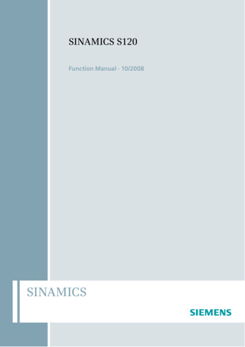
Type 2A Arc Resistant tiastar Motor Control CenterSpecial instructionstiastar Motor Control Center – RearTop cover plate pressure relief flaps To relieve internal pressure, flaps open outward in the eventof an arc fault.WARNINGWARNINGEnd Covers Heavy gauge to withstand pressure from internal arcing faults.Rear Covers Extra screws to withstand pressure from internal arcing faults. U-nuts to provide extra threads. Screws thread into u-nuts which prevent stripping of threads andprovide extra strength to backplate.Figure 2. Rear isometric view of motor control centerWARNINGWARNINGtiastar Motor Control Center – Front Top wire way doors and vertical wire way door are screweddown to withstand pressure. Doors with ventilation have plates or flaps to deflect gasses anddebris escaping from the MCC. Blank spaces, 16” wide are limited to 6” or 12” height and arebolted to withstand pressure.30” – 60” unit compartmentFigure 3. Front isometric view of motor control center30” – 60” unit compartment parts (plug-in only) Unit is screwed to the wireway backplate/ structure. Heavy gauge right side angle with door fastener slots. Unit is bolted through the bottom plate in two locations.Figure 4. Isometric view of 30” – 60” compartment6
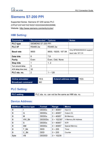
Type 2A Arc Resistant tiastar Motor Control CenterInstallationMCC dimensions, room requirements and other considerationsRestricted top conduit entry:1. Clear space must be maintained in front, sides and above thetiastar Motor Control Center. If a rear and/or side aisle is used,it must be a minimum of 38”. The details are as shown:Restricted top conduit entry: Use of special expansion2. Expansion coperating conditions.must be closed under normal3. Clear space of 9” required over expansion chamber aps.chamber on top of Arc Resistant MCC restricts the availableThese conduit openings have to be cut into the expansionchamber top plate.ventilated units should be open under4. All internalnormal operating conditions and should be free to swingclosed in the event of an arcncident.5. Ensure that all screws are in place and tightened beforeenergizing the equipment.Pressureflap20Deep(3) 4” Conduitsor(4) 3” ConduitsUnitDoor176 3/4WirewayDoorFigure 6. Top conduit opening for Arc Resistant MCC- Use of conduit for cable entry recommended- If conduit is not used then a means of sealing around cables eitherwith a listed gland or listed industrial fire barrier is required.112" MIN.CEILING HEIGHT115” MIN.FOR USE WITHPLENUM38" MIN SPACEIF SIDES OR REAR AREACCESSABLE38" AISLE SPACEFigure 57
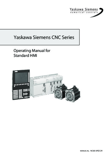
Type 2A Arc Resistant tiastar Motor Control CenterExpansion chamber installationFigure 7Refer to Figure 7 for the following procedure.1. Remove top front conduit plate (A) from motor control center structure by removing two screws (B).2. Remove two rear screws (C) and top rear conduit plate (H)3. Remove the top two screws holding on the bus insulator cover (E).4. Install barrier (F) and replace the screws from step 3.5. Remove entire top plate assembly of expansion chamber(G) along with pressure flap.6. Place expansion chamber on MCC and screw down using four 1/4-20 x 3/4” taptite screws.7. Replace top plate assembly that was removed in step five.8
Type 2A Arc Resistant tiastar Motor Control CenterPlenum/duct design guidelinesRelevant definitions (see Drawing 1)1. Plenum: Expansion chamber on top of MCC section.2. Exhaust Duct: Channel/ tube to carry the gasses away fromMCC. It is attached to the plenum on one side and duct endassembly on the other side.3. Duct end assembly: Assembly at the end of the exhaust ductconsisting of pressure flap, mesh and shroud. Duct endassembly will protrude outside the E house or building housingthe MCC (see Drawing 4 and Drawing 5).4. Pressure flap: Flap at end of the duct designed to open in anArc Flash incident.5. Plenum system: Entire assembly constituting of the plenum,exhaust duct and duct end assemblyOverall configuration of plenum system (see Drawing 1)As shown in the attached drawing the plenum can have 4 generalinitial orientations:A. Plenum system oriented towards the front of the MCC lineupB. Plenum system oriented towards the back of the MCC lineupC. Plenum system oriented towards the left of the MCC lineupD. Plenum system oriented towards the right of the MCC lineupThe duct can have multiple turns in any direction as needed toreach its desired exhaust location.Details of Plenum construction (see Drawing 2)As shown in drawing 1, the plenum is mounted to the top of theMCC structure.Specifically it gets mounted to the transition (adapter) plate with5/16-18 machine screws. The adapter plate is part of the ArcResistant MCC structure. The exhaust duct attaches to the plenumas shown in drawing and depending upon the location of theexhaust duct, one or more plenums can have suitable openingsand bolt patterns for the duct to attach to. The size of theopening should be the same as or more than correspondinginterior dimensions of the exhaust duct so as to not cause anyhindrance to the travel of the pressure wave and passage ofsmoke and gasses. Adjacent plenums bolt to each other usinghole pattern on flanges with 5/16-18 hardware.Details of side cover (see Drawing 3)New side covers are needed when using the plenum instead of aregular expansion chamber. The drawing D67705396 details theside covers to be used on both sides for the assembly based for“front” and “back” configurations. For left and right configurationssince the plenum exhaust duct would be extending towards oneside of the MCC lineup, suitable modifications can be made to thatparticular side cover keeping the mounting hole patterns shown inregion ‘A’.Details of exhaust duct (see Drawing 4)The exhaust duct is attached to the plenum on one side and isattached to the pressure relief valve on the other side. Theminimum cross section that an exhaust duct can have is 270 sq.in. with one of the dimensions being at least 15 in. The materialused for construction is 13GA steel (min thickness). The exhaustduct should not have any interior restrictions or hindrances whichmight block the flow of gasses and the pressure wave through it.The exhaust duct can have as many turns and twist as needed toget to the intended exhaust location provided the interior crosssection is maintained. There are no restrictions on the length orthe orientation of the exhaust duct.Alternate construction: Instead of the 13Ga steel mentioned inthe previous paragraph, one can also use an HVAC duct made perASHRAE standards and of 24GA steel (min thickness) to attach tothe plenum and the duct end assembly.Duct end assembly (see Drawing 5)The duct end assembly is attached to the other end of the exhaustduct away from the MCC. It consists of pressure flap, mesh andshroud. The interior cross section area of duct and the materialused in the duct end assembly (except the flap and shroud) shouldbe the same as that of the exhaust duct. As seen in drawing thepressure flap is closed under normal operating conditions and ishinged at the bottom which enables it to open freely when itsenses a pressure wave inside the duct. Gravity helps in keepingflap open once it has opened. Shroud over the flap keeps rain.snow and other contaminants from falling directly over thepressure flap. Wire mesh under the flap prevents rodents fromcrawling inside the exhaust duct once flap is opened and thusprovides additional protection.Restricted area near duct end assembly outside the building(see Drawing 5)In order to keep personnel and equipment safe in the event of anArc Flash incident, the immediate vicinity of the exhaust of theduct is to be kept clear of personnel and other flammable material.Strong pressure waves are generated during an Arc Fault which arecarried through the plenum and the duct outside the building. Thusthe immediate surroundings of the pressure relief valve are to bekept clear so that this pressure wave dissipates before causing anyharm to equipment or personnel.9
Type 2A Arc Resistant tiastar Motor Control CenterPlenum/duct design guidelinesAdditional Notes:a. Make sure all bolted connections are securely tightened.b. Make sure the duct is adequately supported.c. Ensure that there are no openings in either the plenum or ductassembly. If after assembly of sheet metal parts such openingexist, these should be inspected and closed with appropriategaskets and/or caulk.d. Ensure that the pressure relief device flap is always closed inthe normally operating condition and is free to rotate on itshinges in case of an Arc Fault.Type 2A arc resistant tiastar Motor Control CenterPlenum/duct drawings1. Drawing 1 Overall configuration of Plenum and duct2. Drawing 2 Details of Plenum construction3. Drawing 3 Details of Side Cover4. Drawing 4 Design guidelines for Duct and Pressurerelief device5. Drawing 5 Design guidelines for restricted area nearpressure relief device outside building10
Type 2A Arc Resistant tiastar Motor Control CenterDrawingsDRAWING 1DRAWING 111
Type 2A Arc Resistant tiastar Motor Control CenterDrawingsDRAWING 2DRAWING 2USE GRADE 5 5/16-18HARDWARE TO ATTACHTO TRANSITION PLATE12
Type 2A Arc Resistant tiastar Motor Control CenterDrawingsDRAWING 3PAINT ANSI GREY 61 OR EQUIVALENT3. ALL DIMENSIONS ARE IN INCHES13
Type 2A Arc Resistant tiastar Motor Control CenterDrawingsDRAWING 40.500(SHROUD)TICAL18 GA STEEL. FLAP MUST BE ABLE TO OPEN WITH SHROUD ASSEMBLEDWALL OPENING 0.5” GREATER THANOUTSIDE DIM OF SHROUDWALL OPENING0.5” GREATER THANOUTSIDE DIM OF SHROUDHINGES ALLOW FREE ROTATION OF FLAPFIELD CAULK ALL AROUNDBETWEEN OPENING OFWALL AND DUCTANSI 61 GREY OR EQUIVALENT5. DUCT END TO BE MADE OF SAME MATERIAL ASDUCT EXCEPT PRESSURE FLAP AND SHROUD14EXHAUSTDUCT - SEEGUIDELINE 7
Type 2A Arc Resistant tiastar Motor Control CenterDrawingsDRAWING 5DUCT END ASSEMBLYFIGURE SHOWS THE MINIMUM RECOMMENDED CLEARANCEFROM THE EXHAUST OF THE PLANUM. WHEN THE EQUIPMENTIS OPERATING, THI S AREA SHOULD BE KEPT CLEAR OFPERSONNEL AND/OR COMBUSTIBLE MATERIALS.NOTE: ALL DIMENSIONS ARE IN INCHES15
Siemens Industry, Inc.5300 Triangle ParkwayNorcross, GA 30092Subject to change without prior notice.A5E31166440A-003Order Number: CCIG-ARCIG-02161-800 -241- 4453info.us@siemens.comAll rights reserved.Printed in USA 2016 Siemens Industry, Inc.www.usa.siemens.com/mccThe information provided in this brochure contains merelygeneral descriptions or characteristics of performancewhich in case of actual use do not always apply as describedor which may change as a result of further developmentof the products. An obligation to provide the respectivecharacteristics shall only exist if expressly agreed in theterms of contract.All product designations may be trademarks or productnames of Siemens AG or supplier companies whose use bythird parties for their own purposes could violate the rightsof the owners.
of the motor control center. If accessible space is used on the sides or rear of the motor control center provide a minimum 38 inches. A 112 inch minimum ceiling height must be maintained for proper functioning of arc resistant motor control center. The arc resistant ratings are listed on the motor control center rating label. Ratings are given .