Transcription
EMMS-T40105-00-4AUSSIERS retractable stabstiastar low-voltage motor control centersinstruction manualusa.siemens.com/mcc
tiastar SIERS retractable stabs Instruction manualHazardous voltages and high-speed moving parts.Will cause death, serious injury, or property damage.Always de-energize and ground the equipment before maintenance. Readand understand this instruction manual before using equipment.Maintenance should be performed only by qualified personnel. The use ofunauthorized parts in the repair of the equipment or tampering byunqualified personnel will result in dangerous conditions which will causedeath, severe injury, or equipment damage. Follow all safety instructionscontained herein.ImportantThe information contained herein is generalin nature and not intended for specificapplication purposes. It does not relieve theuser of responsibility to use sound practicesin application, installation, operation, andmaintenance of the equipment purchased.Siemens reserves the right to make changesin the specifications shown herein or tomake improvements at any time withoutnotice or obligation. Should a conflict arisebetween the general information containedin this publication and the contents ofdrawings or supplementary material orboth, the latter shall take precedence.Qualified personFor the purpose of this instruction manual aqualified person is one who hasdemonstrated skills and knowledge relatedto the construction and operation ofelectrical equipment and installations andhas received hazard safety training toidentify the hazards and reduce theassociated risk. In addition, this person hasthe following qualifications: Is trained and authorized to deenergize, clear, ground and tag circuitsand equipment in accordance withestablished safety procedures. Is trained in the proper care and use ofprotective equipment, such as: rubbergloves, hard hat, safety glasses or faceshields, flash clothing, etc. in accordancewith established safety practices.2 Is trained in rendering first aid. Is trained in the methods of safe releaseof victims from contact with energizedelectrical conductors or circuit parts.Further, a qualified person shall also befamiliar with the proper use of specialprecautionary techniques, personalprotective equipment, insulation andshielding materials, and insulated tools andtest equipment. Such persons are permittedto work within limited approach boundary,and shall, at a minimum, be additionallytrained in all of the following: The skills and techniques necessary todistinguish exposed energized parts fromother parts of electric equipment. The skills and techniques necessary todetermine the nominal voltage ofexposed live parts. The approach distances specified in NFPA70E and the corresponding voltages towhich the qualified person will beexposed. The decision-making process necessaryto perform the job safety planning,identify the electrical hazards, assess theassociated risks, and select theappropriate risk control methodsincluding personal protective equipment
Instruction manual tiastar SIERS retractable stabsNote:These instructions do not purport to cover all details or variations inequipment, nor to provide for every possible contingency to be met inconnection with installation, operation, or maintenance. Should furtherinformation be desired or should particular problems arise that are notcovered sufficiently for the purchaser’s purposes, the matter should bereferred to the local sales office.The contents of this instruction manual shall not become part of ormodify any prior or existing agreement, commitment or relationship.The sales contract contains the entire obligation of Siemens Industry,Inc. The warranty contained in the contract between the parties is thesole warranty of Siemens Industry, Inc. Any statements contained hereindo not create new warranties or modify the existing warranty.Instruction manualIntroduction 04Receiving, handling, and storage 05SIERS system overview 08Removing an existing unit without SIERS system 10Installing a unit with the SIERS system 12Operating the SIERS system 13Uninstalling a unit with the SIERS system 16Operating the SIERS system with the remote operator 18Outgoing power and control wiring 21Handle operation and maintenance 22Pre-operation checks 253
tiastar SIERS retractable stabs Instruction manualIntroductionHazardous voltages and high-speed moving parts.Will cause death, serious injury, or property damage.Always de-energize and ground the equipment before maintenance. Readand understand this instruction manual before using equipment.Maintenance should be performed only by qualified personnel. The use ofunauthorized parts in the repair of the equipment or tampering byunqualified personnel will result in dangerous conditions which will causedeath, severe injury, or equipment damage. Follow all safety instructionscontained herein.IntroductionThis instruction manual supplements theinstruction manual for the type tiastarlow-voltage motor control centers anddescribes the SIERS for tiastar optionalfeature.Signal wordsThe signal words “danger,” “warning”, and“caution” used in this instruction manualindicate the degree of hazard that may beencountered by the user. These words aredefined as:Refer to the instruction manuals for specificlow-voltage motor control centercomponents.Danger - Indicates an imminently hazardoussituation that, if not avoided, will result indeath or serious injury.Read, understand, and follow all of thesafety advisories, instructions, andprocedures contained in the referencemanuals. For convenience, these instructionmanuals will hereafter be referred to as thebasic equipment manuals.Warning - Indicates a potentially hazardoussituation that, if not avoided, could result indeath or serious injury.The retractable stab option allows theoperator to connect and disconnect the unitstabs from the vertical bus in a low-voltagemotor control section without opening thedoor. The optional remote operator can beused to operate the system from a distance.Caution - Indicates a potentially hazardoussituation that, if not avoided, may result inminor or moderate injury.Notice - Indicates a potentially hazardoussituation that, if not avoided, may result inproperty damage.Field service operation andwarranty issuesSiemens can provide competent, welltrained field service representatives toprovide technical guidance and advisoryassistance for the installation, overhaul,repair, and maintenance of Siemensequipment, processes and systems. Contactregional service centers, sales offices or thefactory for details, or telephone Siemensfield service at 1 (800) 333-7421 or 1 (423)262-5700 outside the U.S.For customer service issues, contactSiemens at 1 (800) 333-7421 or 1 (423)262-5700 outside the U.S.4
Instruction manual tiastar SIERS retractable stabsReceiving, handling, and storageHeavy weight.Can result in death, serious injury, or property damage.Observe all handling instructions in this instruction manual to preventtipping or dropping of equipment.ReceivingEach shipping split of tiastar low-voltagemotor control center is securely blocked andbraced for shipment. It is wrapped, boxed,or covered as required by shippingconditions. If special handling is required, itis so indicated. As relatively delicateinstruments, relays, and other devices maybe included, the assembly must be handledcarefully when unloading.IdentificationWhen the shipment includes more than oneunit/shipping group or equipment for morethan one location, marking tags areattached to each package for identification.The sales order number on the tag is also onthe shipping list. The shipping list identifiesthe contents with the unit numbers includedin the shipping group. Refer to the generalarrangement drawing for the location ofeach unit within the group lineup. Use thisinformation to simplify the assemblyoperation and save unnecessary handling.Inspection and unpackingInspect the equipment as soon as possibleafter receipt for any damage that may haveoccurred in transit. Before unpacking,examine the package itself, as a damagedpackage may indicate damage to thecontents of the package. Be careful whenunpacking equipment.The use of sledge hammers and crowbarsmay damage the finish or the equipmentitself and may void the warranty. Use nailpullers. After unpacking, examineequipment for any possible damage. Checkthe shipping manifest to be certain that allitems have been received.Note: If there is a shortage, make certain itis noted on the freight bill and contact thecarrier immediately. Notify Siemenscustomer service 1 (800) 333-7421 ( 1(423) 262-5700 outside the U.S.) of anyshortage or damage.Shipping damage claimsImportant: The manner in which visibleshipping damage is identified by consigneeprior to signing the delivery receipt candetermine the outcome of any damageclaim to be filed.Notification to carrier within 15 days forconcealed damage is essential if lossresulting from unsettled claims is to beeliminated or minimized.1. When shipment arrives, note whetherequipment is properly protected from theelements. Note trailer number on whichthe equipment arrived. Note blocking ofequipment. During unloading, make sureto count the actual items unloaded toverify the contents as shown on thedelivery receipt.5
tiastar SIERS retractable stabs Instruction manual2. Make immediate inspection for visibledamage upon arrival and prior todisturbing or removing packaging orwrapping material. This should be doneprior to unloading when possible. Whentotal inspection cannot be made onvehicle prior to unloading, closeinspection during unloading must beperformed and visible damage noted onthe delivery receipt. Take pictures ifpossible.3. Any visible damage must be noted on thedelivery receipt and acknowledged withthe driver’s signature. The damage shouldbe detailed as much as possible. It isessential that a notation “possible internaldamage, subject to inspection” beincluded on delivery receipt. If the driverwill not sign the delivery receipt withdamage noted, the shipment should notbe signed for by the consignee or theiragent.4. Notify Siemens immediately of anydamage, at 1 (800) 333-7421 or 1 (423)262-5700 outside the U.S.5. Arrange for a carrier inspection ofdamage immediately.Important: Do not move equipment fromthe place it was set when unloading. Also,do not remove or disturb packaging orwrapping material prior to carrier damageinspection. Equipment must be inspected bycarrier prior to handling after receipt. Thiseliminates loss due to claims by carrier thatequipment was damaged or furtherdamaged on site after unloading.6. Be sure equipment is properly protectedfrom any further damage by covering itproperly after unloading.7. If practical, make further inspection forpossible concealed damage while thecarrier’s inspector is on site. If inspectionfor concealed damage is not practical atthe time the carrier’s inspector is present,it must be done within 15 days of receiptof equipment. If concealed damage isfound, the carrier must again be notifiedand inspection made prior to taking anycorrective action to repair. Also notifySiemens immediately at 1 (800) 3337421 or 1 (423) 262-5700 outside theU.S.68. Obtain the original of the carrierinspection report and forward it alongwith a copy of the noted delivery receiptto Siemens at 1 (800) 333-7421 or 1(423) 262-5700 outside the U.S. Approvalmust be obtained by Siemens from thecarrier before any repair work can beperformed. Before approval can beobtained, Siemens must have the abovereferenced documents. The carrierinspection report and/or driver’s signatureon the delivery receipt does notconstitute approval to repair.Note: Shipments are not released from thefactory without a clear bill of lading.Approved methods are employed forpreparation, loading, blocking, and tarpingof the equipment before it leaves theSiemens factory. Any determination as towhether the equipment was properly loadedor properly prepared by shipper for over-theroad travel cannot be made at thedestination. If the equipment is received in adamaged condition, this damage to theequipment must have occurred while enroute due to conditions beyond Siemens’control. If the procedure outlined above isnot followed by the consignee, purchaser, ortheir agent, Siemens is not liable for repairs.Siemens is not liable for repairs in any casewhere repair work was performed prior toauthorization from Siemens.Indoor equipment handlingThere are a number of methods thatproperly trained employees can use inhandling tiastar low-voltage motor controlcenters that will not damage the equipment.The handling method used will bedetermined by conditions and availableequipment at the installation site.Before removing the protective packingmaterials, the low-voltage motor controlsections may be moved by crane with liftcables attached through the packaging tothe lifting plates on the top of theequipment.
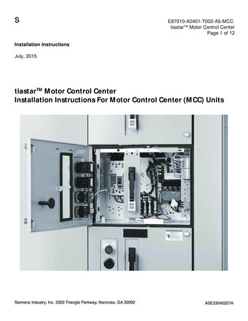
Instruction manual tiastar SIERS retractable stabsLifting with a crane is the preferred methodof handling; however, overheadobstructions or low ceilings often dictatethat other methods must be used. If cranefacilities are unavailable, or if tight spacesprevent the use of a crane, rollers, jacks orforklift trucks under the wooden shippingskids may be used. tiastar low-voltage motorcontrol centers are shipped in groups of oneto four vertical sections mounted onwooden shipping skids and wrapped, boxed,or covered. Individual units are shippedeither in boxes or crates depending on unitsize. Remove protective packing in shippingcontainer to access unit.Receiving and inspectionBecome familiar with the unit and unitsupport components. Carefully remove allpackaging material from the unit. Read theentire unit installation guide. And inspectthe unit for damage. Become familiar withthe unit and unit support componentsdescribed in the images below. Refer toFigures 1 and 2.Each group has provisions for attachinglifting equipment to the top of the sections.Figure 1: Unit components654Item1Door interlock2Pilot device panel(used whenmounting directlyto unit)3Operating handle4Racking lever5Racking lever lockplate6Top barrier plate7Terminal block1322Description7Figure 2: Unit support components1ItemDescription1Pin-type door hinge2Shelf bracket3Separator angle4Intermediate angle4237
tiastar SIERS retractable stabs Instruction manualSIERS system overviewHazardous voltages.Will cause death, serious injury, or property damage.The door interlock should be defeated only by authorized personnel in theevent of a malfunction in the equipment.Hazardous voltages.Will cause death, serious injury, or property damage.Do not attempt to use excessive force or leverage to overpower anymechanical interlock systems. Malfunctions must be serviced by qualifiedpersonnel only.Do not attempt to modify, override, or uninstall any mechanical interlocksystems.Important: These instructions do notpurport to cover all details or variations inequipment, nor to provide for every possiblecontingency to be met in connection withinstallation, operation or maintenance.Should further information be desired orshould particular problems arise which arenot covered sufficiently for the purchaser’spurposes, the matter should be referred tothe local Siemens sales office. The contentsof this instruction manual shall not becomepart of or modify any prior or existingagreement, commitment or relationship.The sales contract contains the entireobligation of Siemens. The warrantycontained in the contract between theparties is the sole warranty of Siemens. Anystatements contained herein do not createnew warranties or modify the existingwarranty.8SIERS system overviewPlug-in units equipped with the tiastarretractable stabs mechanism (SIERS) provideadditional levels of functionality to thecustomer. The system allows an operator todisconnect the stabs of the plug-in unit fromthe vertical bus of a tiastar section withoutaccessing the inside of either the section orthe bucket.The SIERS system utilizes a series ofintegrated interlocking systems to protectboth the operator and the mechanism.These interlock systems are included toguard against unintended use of themechanism.It is important to become familiar with thefeatures of the retractable stabs system.
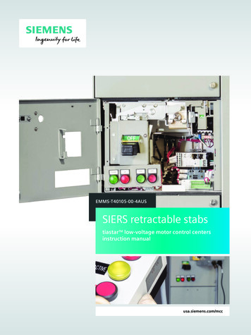
Instruction manual tiastar SIERS retractable stabs814695107362Figure 3: SIERS unit components1. Racking lever lock plate.2. Pilot device panel (if equipped).3. Operating handle.4. Racking lever.5. SIERS drive socket.6. Access interlock: Prevents users fromoperating the mechanism when thecircuit breaker or disconnect switch is inthe ON position. With the handle in theON position, the access port to operatethe mechanism is shielded.8. SIERS mechanism-to-section interlock:When the mechanism is in the extendedposition, the bucket cannot be removedfrom the section.9. Handle bucket-to-section interlock: Whenthe handle is in the ON position, thebucket cannot be removed from thesection.10. Mid-position interlock: Prevents the userfrom operating the circuit breaker intothe ON position while the mechanism isin an intermediate state.ItemDescription1Racking lever lockplate2Pilot device panel3Operating handle4Racking lever5SIERS drive socket6Access interlock7Door interlock8Mechanism-tosection interlock9Handle-to-sectioninterlock10Mid-position interlock7. Door interlock: When the door is open,the circuit breaker handle cannot beoperated to the ON position. Additionally,when the circuit breaker is in the ONposition, the door cannot be openedwithout defeating the interlock.9
tiastar SIERS retractable stabs Instruction manualRemoving an existing unitwithout SIERS systemRecommendedhand tools: Flat-head screwdriver Phillips-headscrewdriver 3/8” drive rachet 3/8” drive extension bar.1. Move disconnect operating handle to theOFF position.2. Open the unit door; transfer any attachedpilot devices from door to slot on unit.3. Unscrew latch located at the bottom ofthe unit. Rotate the latch until itdisengages from the separator angle(refer to Figure 8).4. Open the vertical wireway.5. Loosen the lock bar in the top right androtate it out of the way of the rackinglever.6. Rotate the racking lever out of the unit.7. Disconnect control and load wiring fromthe unit.8. Remove unit by pulling forward andslightly tilting the front of the unitdownward and sliding it out of thestructure.109. If rearranging different size units,perform the following tasks: 9a. Removeall unit support assemblies byunfastening the screws for eachassembly, tilting upward, and slidingout of their holes. 9b. Realignsupport assemblies as needed. 9c. Includeintermediate angles in allspaces where a plug-in unit will not beinstalled. 9d. Removestab-hole covers atappropriate heights and replacecovers on unused stab holes. Stabhole covers should be arranged sothat the only uncovered openings arethose to which a unit will beconnected (refer to Figure 5). 9d1. Motorcontrol centers withautomatic shutters; tiastarshutter mechanism kit 8PG11912MA00 can be ordered ifadditional shutters are needed.
Instruction manual tiastar SIERS retractable stabsFigure 4: Tightening rackinglever lock barFigure 5: Uncovered stab holes11
tiastar SIERS retractable stabs Instruction manualInstalling a unit withthe SIERS system1. If present, remove existing door by firstwithdrawing its hinge pins and thenclosing the door halfway before sliding itoff its hinges.2. If installing the plug-in unit in apreviously blank location, theintermediate angle will need to beremoved. Do so by removing the screwthat fastens it to the separator angle andtipping slightly to remove the formed tabat the top from slot on shelf bracketabove.Figure 6: Placing unit on support assembly and in TEST position3. If necessary, install unit-support assemblyby inserting shelf brackets at a slightangle into the appropriate holes in thevertical bus-support angle and snappinginto place (refer to Figure 2). Securesupport assembly with the two screwsprovided. One screw fastens the righthand shelf bracket to the vertical bussupport angle. The second screw fastensthe separator angle to the left side of thestructure.4. If necessary, remove appropriate unitstab-hole covers.5. Install unit door by sliding it onto thehinges while half open. Once on thehinges, open the door completely andinsert hinge pins.6. Any plug-in unit equipped with the SIERSsystem must be in the DISCONNECTEDposition before installing it into a tiastarsection. In the DISCONNECTED position,the stabs are retracted into the unit andthe position indicator will show adisconnect symbol and greenbackground. 6a. IfFigure 7: Closing racking lever12the SIERS system is not in theDISCONNECTED position, the systemmust be placed in the DISCONNECTEDposition. First verify that the powerhandle is in the OFF position. Formore information on this process,refer to “Handle operation andmaintenance” on page 22 and toFigure 10.
Instruction manual tiastar SIERS retractable stabs 6 b. Next,place the SIERS system in theDISCONNECTED position. Refer tosection “Disconnecting the SIERSsystem” on page 14 and execute stepstwo through four.7. Place plug-in unit inside of the enclosure(refer to Figure 6). 7e. Engagethe racking lever lock bar inthe upper right corner of the unit.Adjust it so that it locks the rackinglever in the RACKED position andtighten down with a flat-headscrewdriver (latch shown in correctlyinstalled position in Figure 9). 7 a. Withthe handle in the OFF position,slide unit into place on supportassembly. 7 b. Slightlytilt the front of the unitdownwards in order to slide the backof the unit over the shelf brackets. 7 c. Oncethe unit has been pushed in asfar as it can go, close the racking leverin top barrier plate (refer to Figure 7). 7 d. Engagelocking latch at lower left ofthe unit to the separator angle andtighten it using a flat-headscrewdriver (refer to Figure 8)Figure 8: Lower locking latchFigure 9: Racking lever lock bar incorrectly installed positionOperating the SIERS systemHazardous voltages and high-speed moving parts.Will cause death, serious injury, or property damage.Do not attempt to use excessive force or leverage to overpower anymechanical interlock systems. Malfunctions must be serviced by qualifiedpersonnel only.Do not attempt to modify, override, or uninstall any mechanical interlocksystems.Connecting the SIERS system3. Rotate the tool clockwise approximately1. With the door closed, verify that the unit’s22 turns (refer to Figure 14). Thepower handle is in the OFF position (refermechanism should rotate smoothly withto Figure 12). (When the handle is in theminor resistance when engaging theON position, it is not possible to access tostabs onto the vertical bus. When thethe SIERS system’s drive socket.) Morestabs reach the fully extended position,information on handle operation can bethe mechanism will hit the rear bumpfound in “Handle operation andstop and an increase in resistance will bemaintenance” on page 22.felt by the operator. Do not apply morethan 125 in-lb (14 Nm) of torque to the2. If the door has a cover plate, lift it up toSIERS drive socket.expose the SIERS drive socket. With thecover plate lifted insert the 3/8” squaredrive into the SIERS drive socket (refer toFigure 13).13
tiastar SIERS retractable stabs Instruction manual4. Check the position indicator on front ofunit to verify that the mechanism is in theCONNECTED position. The CONNECTEDposition is represented by a red colorbackground and closed circuit symbol(refer to Figure 15).5. At this time, the system is fully installedonto the vertical bus and the unit’s powerhandle can now be operated to the ONposition.Disconnecting the SIERS system1. With the door closed, verify that the unit’spower handle is in the OFF position.(When the handle is in the ON position, itis not possible to access to the retractableSIERS drive socket.) More information onhandle operation can be found in “Handleoperation and maintenance” on page 22.2. Insert the 3/8” square drive into the SIERSdrive socket (refer to Figure 13).3. Rotate the tool counter-clockwiseapproximately 22 turns (refer to Figure16). The mechanism should rotatesmoothly with minor resistance whendisengaging the stabs from the verticalbus. When the stabs reach the fullyretracted position, the mechanism will hitthe front bump stop and an increase inresistance will be felt by the operator. Donot apply more than 125 in-lb (14 Nm) oftorque to the SIERS drive socket.Figure 10: Operating handle position: ON4. Check the position indicator on front ofunit to verify that the mechanism is in theDISCONNECTED position. TheDISCONNECTED position is represented bya green color background and opencircuit symbol (refer to Figure 17).5. At this time, the system is disconnectedfrom the vertical bus.Figure 11: Operating handle position: TRIPPEDFigure 13: Inserting 3/8” drive extension into SIERSdrive socketFigure 12: Operating handle position: OFF14
Instruction manual tiastar SIERS retractable stabsFigure 14: Rotate tool clockwise to extend stabs andplace the SIERS’ system in the CONNECTED positionFigure 15: SIERS system position indicator inCONNECTED positionFigure 16: Rotate tool counter-clockwise to retractstabs and place the SIERS’ system in theDISCONNECTED positionFigure 17: SIERS system position indicator inDISCONNECTED position15
tiastar SIERS retractable stabs Instruction manualUninstalling a unit withSIERS system1. Any plug-in unit equipped with the SIERSsystem must be in the DISCONNECTEDposition before uninstalling it from atiastar section. In the DISCONNECTEDposition, the stabs are retracted into theunit and the position indicator will showa disconnect symbol and greenbackground. 1a. Ifthe SIERS system is not in theDISCONNECTED position, the systemmust be placed in the DISCONNECTEDposition. To place the retractable stabssystem in the DISCONNECTEDposition, review the section titled“Disconnecting the SIERS system” onpage 14 inside of section “Operatingthe SIERS system” and execute stepsone through five.CloseOpenFigure 18: Closing or opening racking lever162. Open the unit door; transfer any attachedpilot devices from door to slot on unit.3. Unscrew latch located at the bottom ofthe unit. Rotate the latch until itdisengages from the separator angle(refer to Figure 8).4. Open the vertical wireway.5. Disconnect control and load wiring fromthe unit.6. Loosen the lock bar in the top right androtate it out of the way of the rackinglever.7. Rotate the racking lever out of the unit.8. Remove unit by pulling forward andslightly tilting the front of the unitdownward and sliding it out of thestructure.
Instruction manual tiastar SIERS retractable stabsFigure 19: SIERS system position indicator in CONNECTED position17
tiastar SIERS retractable stabs Instruction manualOperating the SIERS systemwith the remote operatorThe remote operator for the SIERS systemallows the user to remotely connect anddisconnect the unit stabs from the verticalbus in a low-voltage motor control sectionwithout opening the door.The remote operator kit consists of a remoteoperator and pendant connected to theremote operator with a 30 ft (9.1 m) controlcord.Remote operator kit: One remote operator Hand-held control pendant with 30 ft(9.1 m) of control cable One ac power cord.Installing the remote operator for use1. Verify that the plug-in unit’s powerhandle is in the OFF position and that thedoor is securely closed and latched. Moreinformation about handle operation canbe found in “Handle operation andmaintenance” on page 22.2. If the door has a cover plate, lift it up toexpose the mechanism drive socket. Withthe cover plate lifted, slide the motor’sdrive bar into the mechanism drivesocket. Insert the remote operator driveshaft into the mechanism drive socket.After insertion, rotate the remoteoperator so that the remote operatorhandle points upwards (refer to Figure20).3. While holding remote operator in place,push and twist the magnet handles onthe left and right of the remote operator180 clockwise to the ON position tosecure the remote operator to the unitdoor (refer to Figure 21).4. With the remote operator fully secured tothe door and aligned properly, connectthe control pendant plug and ac powercord to the remote operator. After theyare installed, connect the power cord to astandard 120 Vac power outlet (refer toFigure 22).5. The remote operator is now ready for use.18Using the remote operatorConnecting the SIERS system1. Ensure that the unit being operated is inthe DISCONNECTED position byexamining the position indicator windowand verifying that the power handle is inthe OFF position.2. While holding the control pendant pressand hold the connect button (refer toFigure 23).3. The yellow active light will illuminateindicating power is being delivered to themotor and it is operating (refer to Figure24). Simultaneously, the remote operatorwill begin to operate the mechanism.4. Watch the control pendant. When the redoperation complete light illuminates, themotor has finished connecting the stabsand the connect button should bereleased (refer to Figure 25).5. To confirm a successful connectoperation, visually inspect the positionindicator window. If successful, it willshow a connected electrical symbol witha red background (refer to Figure 26).6. Uninstall the remote operator from theunit door per “Uninstalling the remoteoperator” on page 19.Disconnecting the SIERS system1. Verify that the unit being operated is inthe CONNECTED position by examiningthe position indicator window andverifying that the power handle is in theOFF position. Install the remote operatorper steps two through five of “Installingthe remote operator for use.”2. While holding the pendant, press andhold the disconnect button (refer toFigure 27).3. The yellow active light will illuminatei
low-voltage motor control centers and describes the SIERS for tiastar optional feature. Refer to the instruction manuals for specific low-voltage motor control center components. Read, understand, and follow all of the safety advisories, instructions, and procedures contained in the reference manuals. For convenience, these instruction