Transcription
HP ProLiant DL/ML370 G6 ServerUser GuidePart Number 513482-002October 2010 (Second Edition)
Copyright 2009, 2010 Hewlett-Packard Development Company, L.P.The information contained herein is subject to change without notice. The only warranties for HP products and services are set forth in the expresswarranty statements accompanying such products and services. Nothing herein should be construed as constituting an additional warranty. HPshall not be liable for technical or editorial errors or omissions contained herein.Microsoft, Windows, and Windows Server are U.S. registered trademarks of Microsoft Corporation.Intended audienceThis document is for the person who installs, administers, and troubleshoots servers and storage systems.HP assumes you are qualified in the servicing of computer equipment and trained in recognizing hazardsin products with hazardous energy levels.
ContentsComponent identification . 7Front panel components . 7Front panel LEDs and buttons . 8Systems Insight Display LEDs . 9Systems Insight Display LED combinations . 9Rear panel components . 11Rear panel LEDs . 12System board components . 13DIMM slots . 14System maintenance switch . 14NMI functionality . 15SAS and SATA device numbers . 16SAS and SATA hard drive LEDs. 17SAS and SATA hard drive LED combinations . 17Fans . 18Battery pack LEDs . 19FBWC module LEDs . 21Power supply backplane connectors . 21Drive cage jumper configuration settings . 22Setup. 23Optional installation services . 23Rack planning resources. 23Optimum environment . 24Space and airflow requirements . 24Temperature requirements . 25Power requirements . 25Electrical grounding requirements . 25Rack warnings . 26Server warnings and cautions . 26Identifying tower server shipping carton contents . 27Identifying rack server shipping carton contents . 27Installing hardware options . 28Setting up a tower server . 28Installing the server into the rack. 29Powering up and configuring the server . 30Installing the operating system. 30Registering the server . 31Operations. 32Power up the server . 32Power down the server . 32Open or remove the tower bezel . 32Extend the server from the rack . 34Remove the access panel. 35Remove fans 1-4 . 36Remove fan 5 . 36
etheBBWC battery pack or the FBWC capacitor pack . 37air baffle . 38fan cage . 39media bay blank . 39DVD-ROM drive . 40hard drive cage blank . 41Hardware options installation . 42Introduction . 42Processor option. 42Memory options . 47Memory subsystem architecture . 47Single-, dual-, and quad-rank DIMMs . 47DIMM identification . 48Memory configurations. 48General DIMM slot population guidelines . 50Installing a DIMM . 52Redundant hot-plug fans option . 53Redundant hot-plug power supply option . 55Power supply configuration . 55Hot-plug power supply calculations . 56Installing a redundant hot-plug power supply . 56Hot-plug SAS hard drive options . 57Installing a hot-plug SAS hard drive . 57Removing a hot-plug SAS hard drive . 58Eight-bay SFF drive cage option . 59Installing the eight-bay SFF drive cage (bay 2) . 59Installing the eight-bay SFF drive cage (bay 3) . 61Six-bay LFF backplane option. 64Installing the six-bay LFF backplane (bay 1) . 65Installing the six-bay LFF backplane (bay 2) . 67Two-bay LFF drive cage option . 69Removable media device options . 73Installing a half-height media device . 73Installing a full-height media device. 74Slimline optical drive option. 76Expansion board options. 78HP NC524SFP Dual Port 10GbE Module option . 80Storage controller option . 84BBWC and FBWC options . 84Installing the cache module . 85Installing the BBWC battery pack or the FBWC capacitor pack . 86HP SAS Expander Card option . 87Graphics adapter option . 88Tower-to-rack conversion kit option . 89HP Trusted Platform Module option . 99Installing the Trusted Platform Module board . 99Retaining the recovery key/password . 101Enabling the Trusted Platform Module. 101Cabling . 102Storage device cabling guidelines . 102Eight-bay SFF drive cage cabling . 102Six-bay LFF backplane cabling . 104
Two-bay LFF drive cage cabling . 105BBWC battery pack and FBWC capacitor pack cabling . 106DVD-ROM drive cabling . 106Slimline optical drive cabling . 107Configuration and utilities . 108Configuration tools . 108SmartStart software . 108HP ROM-Based Setup Utility . 108Array Configuration Utility . 111Option ROM Configuration for Arrays . 112Re-entering the server serial number and product ID . 112Management tools . 113Automatic Server Recovery . 113ROMPaq utility . 113Integrated Lights-Out 2 technology . 114Erase Utility . 114Redundant ROM support . 114USB support . 115Diagnostic tools . 115HP Insight Diagnostics . 115HP Insight Diagnostics survey functionality . 115Integrated Management Log . 116Remote support and analysis tools . 116HP Insight Remote Support software . 116Keeping the system current . 117Drivers . 117Version control . 117ProLiant Support Packs . 118Operating System Version Support . 118Firmware . 118HP Smart Update Manager . 118Change control and proactive notification . 119Care Pack . 119Troubleshooting . 120Troubleshooting resources . 120Pre-diagnostic steps . 120Important safety information . 120Symptom information . 122Prepare the server for diagnosis . 123Loose connections . 123Service notifications . 124Troubleshooting flowcharts . 124Start diagnosis flowchart . 124General diagnosis flowchart . 125Server power-on problems flowchart . 127POST problems flowchart . 130OS boot problems flowchart . 131Server fault indications flowchart . 133POST error messages and beep codes . 135Regulatory compliance notices . 136Regulatory compliance identification numbers . 136
Federal Communications Commission notice . 136FCC rating label . 136Class A equipment. 136Class B equipment . 136Declaration of conformity for products marked with the FCC logo, United States only . 137Modifications . 137Cables . 137Canadian notice (Avis Canadien) . 138European Union regulatory notice . 138Disposal of waste equipment by users in private households in the European Union . 139Japanese notice . 139BSMI notice . 139Korean notice . 140Chinese notice . 140Laser compliance . 140Battery replacement notice. 140Taiwan battery recycling notice . 141Power cord statement for Japan. 141Electrostatic discharge . 142Preventing electrostatic discharge . 142Grounding methods to prevent electrostatic discharge . 142Specifications . 143Environmental specifications . 143Server specifications . 143Power supply specifications . 144Technical support . 146Before you contact HP. 146HP contact information . 146Customer Self Repair . 146Acronyms and abbreviations . 154Index . 157
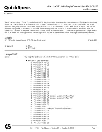
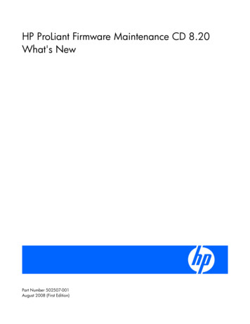
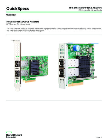
Component identificationFront panel componentsItemDescription1USB connectors (2)2Drive cage blank3SAS/SATA drives (8)4Front video connector (rack model only)5Systems Insight Display6Removable media bay7DVD-ROM drive8Optical drive blankComponent identification 7
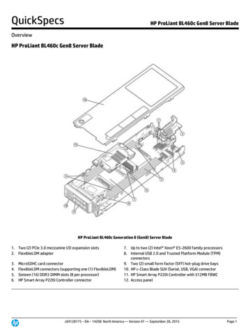
Front panel LEDs and buttonsItemDescriptionStatus1Power On/Standby buttonand system power LEDGreen Normal (system on)Amber System in standby, but power still appliedOff Power cord not attached or power supply failure2Health LEDGreen Normal (system on)Amber System health is degradedRed System health is critical.Off Normal (system off)3UID LEDBlue ActivatedFlashing blue System is being managed remotelyOff DeactivatedComponent identification 8
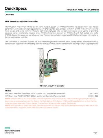
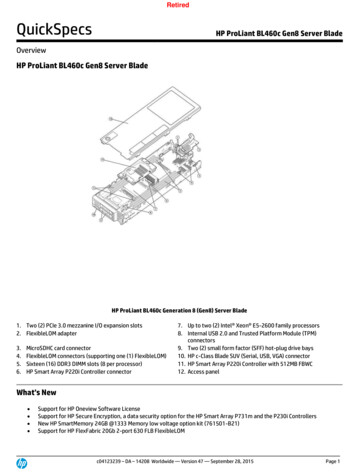
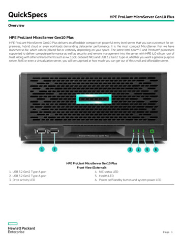
Systems Insight Display LEDsThe HP Systems Insight Display LEDs represent the system board layout.ItemDescriptionStatus1Power capTo determine Power cap status, see"Systems Insight Display LEDcombinations (on page 9)."2AMP StatusGreen AMP mode enabledAmber FailoverFlashing amber Invalid configurationOff AMP mode disabled3DIMM LEDsAll LEDs flashing DIMM unseatedAll other LEDsAmber FailureOff NormalIMPORTANT: If more than one DIMM slot LED is illuminated, further troubleshooting isrequired. Test each bank of DIMMs by removing all other DIMMs. Isolate the failed DIMM byreplacing each DIMM in a bank with a known working DIMM.Systems Insight Display LED combinationsWhen the health LED on the front panel illuminates either amber or red, the server is experiencing ahealth event. Combinations of illuminated Systems Insight Display LEDs, the system power LED, and thehealth LED indicate system status.Component identification 9
Systems InsightDisplay LED and colorHealth LEDSystem powerLEDStatusProcessor (amber)RedAmberOne or more of the following conditionsmay exist: Processor in socket X has failed.Processor X is not installed in thesocket.Processor X is unsupported.ROM detects a failed processor duringPOSTProcessor (amber)AmberGreenProcessor in socket X is in a pre-failurecondition.DIMM (amber)RedGreenOne or more DIMMs have failed.DIMM (amber)AmberGreenDIMM in slot X is in a pre-failure condition.Overtemperature(amber)AmberGreenThe Health Driver has detected acautionary temperature level.Overtemperature(amber)RedAmberThe server has detected a hardware criticaltemperature level.Fan (amber)AmberGreenOne fan has failed or has been removed.Fan (amber)RedGreenTwo or more fans have failed or beenremoved.Power supply (amber)RedAmber Only one power supply is installed andthat power supply is in standby. Power supply fault Redundant power supply is installedand only one power supply isfunctional. AC power cord is not plugged intoredundant power supply. Redundant power supply faultPower supply (amber)AmberGreenSystem board faultPower supply mismatch at POST orpower supply mismatch through hotplug addition.Power cap (off)—AmberStandbyPower cap (green)—Flashing greenWaiting for powerPower cap (flashingamber)—AmberPower cap has been exceededPower cap (green)—GreenPower is availableIMPORTANT: If more than one DIMM slot LED is illuminated, further troubleshooting isrequired. Test each bank of DIMMs by removing all other DIMMs. Isolate the failed DIMM byreplacing each DIMM in a bank with a known working DIMM.Component identification 10
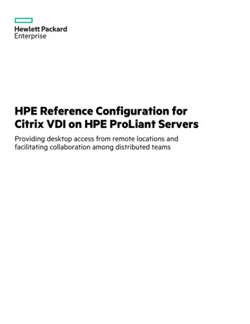
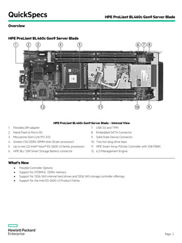
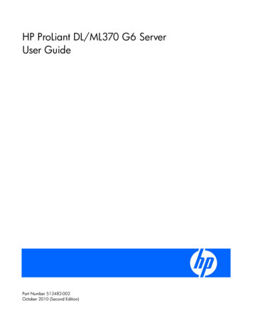
Rear panel componentsItemDescription1Mouse connector2Keyboard connector3Serial connector4iLO 2 connector5USB connectors (2)6NIC connectors (4)
2 AMP Status Green AMP mode enabled Amber Failover Flashing amber Invalid configuration Off AMP mode disabled 3 DIMM LEDs All LEDs flashing DIMM unseated All other LEDs Amber Failure Off Normal IMPORTANT: If more than one DIMM slot LED is illuminated, further troubleshooting is required.