Transcription
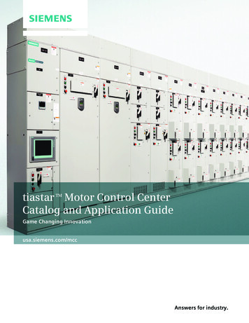
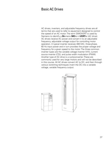
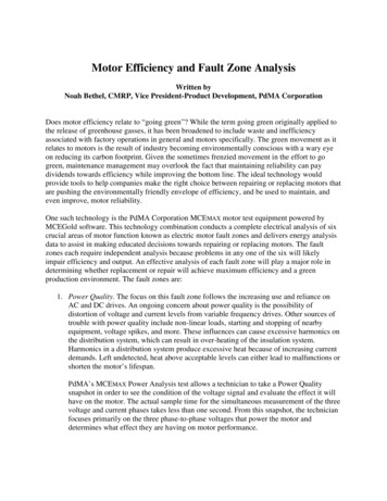
Combination Motor Control UnitsMotor control centers principally contain combination motorcontrol units. NEMA ICS-1-322 states that . . .A combination motor control unit shall include externallyoperable circuit disconnecting means, branch-circuit overcurrentprotection, and a magnetic motor controller with associatedauxiliary devices when used. The disconnecting means andbranch-circuit overcurrent protection shall consist of a fusibledisconnecting device or circuit breaker. If the latter is used,it shall either be an inverse time (thermal-magnetic or dualmagnetic) or an instantaneous magnetic type. The motorcontroller shall include motor and branch-circuit protectionunless equivalent protection is otherwise provided.A combination motor control unit takes all the elementsrequired to control an AC motor and combines them intoone unit. The combination motor control unit in the followingexample uses a molded case circuit breaker to provide circuitdisconnecting means and branch-circuit overcurrent protection.The circuit breaker is opened and closed using the operatinghandle located on the front of the unit. The magnetic motorstarter is used to start and stop an AC motor and provideovercurrent protection for the motor. Pilot devices, located onthe door, serve to provide an operator means to start and stopthe motor as well as provide visual indication of the motor’sstatus.29
Vertical SpaceMost vertical sections provide 72” of vertical space for thecombination motor control units. As many sections as neededwill be assembled together to contain all of the requiredcombination motor control units and other equipment.Wireways run horizontally across the top and bottom of all ofthe sections. A vertical wireway is provided in each verticalsection.DimensionsCombination motor control units are designed to fit into modularcompartments. Typically, the minimum height of a combinationmotor control unit is 12”, increasing in 6” increments (12”, 18”,24”, 30”, up to 72”) as needed. Six combination motor controlunits that are 12” high will fit in 72” of vertical space.30
Installation and RemovalTo simplify installation and removal, combination motor controlunits are provided with self-aligning copper stabs on the backof the control unit. An optional ground bus stab is used when avertical ground bus is supplied. A fixed mounting is used whenthe unit is phsically too large for stabs or rated for greater than250 amps.These stabs engage the vertical bus bars, making the electricalconnection to the control unit. Siemens incorporates a flatvertical bus bar to ensure positive connection between the staband the bus bar.Unit SupportsCombination motor control units are supported in the motorcontrol center on shelf brackets. The brackets can be easilymoved to accommodate different size units. The bracketsguide the combination motor control unit to assure positiveengagement with the vertical bus.31
Review 31.Which of the following is not a part of the NEMAdefinition for motor control centers?a.b.c.d.2.The maximum shipping width of a motor control centeris inches.3.Which of the following illustrates proper NEMA phasearrangement, as viewed from the front?4.A distinguishing feature of motor control centers frompanelboards is that motor control centers .a.b.c.d.5.principally contain combination motor controlunitsprincipally contain branch-circuit protectiondevicesutilize both a horizontal and a vertical busconnect to three-phase powerAccording to NEMA’s definition, which of the following isnot part of a combination motor control unit?a.b.c.d.32Floor-mounted assemblyAllowance for branch-circuit protection unitsCommon horizontal busPrincipally contains combination motor controlunitsexternally operable circuit disconnecting meanscommon horizontal busbranch-circuit overcurrent protectionmagnetic motor controller
Motor StartersThe motor starter is the heart of the combination motor controlunit. Motor starters consist of a contactor and an overload relay.The contactor portion of a motor starter provides the means toremotely start and stop a motor. The overload relay protects themotor from overload conditions.33
Overload RelayTrip ClassesOverload relays are rated by a trip class, which defines thelength of time it will take for the relay to trip in an overloadcondition. The most common trip classes are Class 10, Class 20and Class 30. Class 10, for example, has to trip the motor offline in 10 seconds or less at 600% of the full load amps. This isusually sufficient time for the motor to reach full speed. Manyindustrial loads, particularly high inertia loads, use Class 20.INNOVA PLUSINNOVA PLUS is one type of starter which can be used inmotor control centers. INNOVA PLUS starters are available witha Class 20 melting alloy type overload relay as standard. Class10 or Class 20 ambient compensated or non-compensatedbimetal overload relays are also available.34
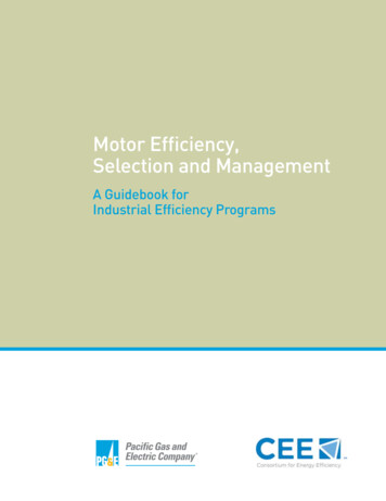
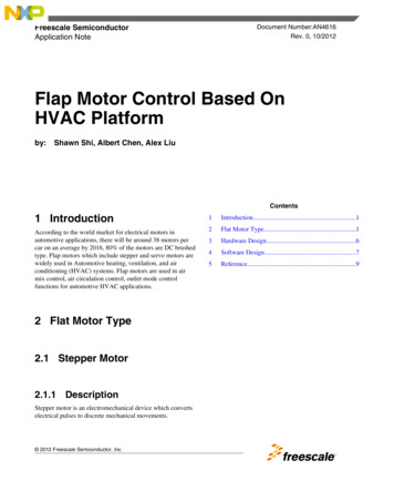
ESP100The Furnas ESP100 starters use the same contactor as theINNOVA PLUS starters. The ESP100 starters are supplied witha Class 10, 20, or 30 solid-state overload relay. The ESP100 alsoprotects the motor against phase loss. The ESP100 trips withinthree seconds of loss of one of the power supply phases.A single ESP100 overload relay replaces at least six size rangesof heaters. Instead of installing heaters the full load amperes(FLA) of the motor is set with a dial. The ESP100 overloadrelay protects 3Ø motors with FLA of ¼ ampere through 540amperes. From ¼ ampere to 10 amperes the overload has a 4:1 FLA range; i.e. 2½ - 10 amperes. Above 10 amperes the rangeis 2:1. The ESP100 overload relay illustrated below, for example,is adjustable from 9 to 18 amperes.35
SAMMSSiemens contactors can also be configured for use with theSiemens Advanced Motor Master System (SAMMS ). TheSAMMS unit is a UL-recognized microprocessor-based motorcontrol and protection device designed specifically for use inmotor control centers. SAMMS provides microprocessor-basedcontrol and protection for all NEMA-rated low-voltage motors.Full communication options are available with SAMMS.SIMOCODE-DPSIMOCODE-DP is another motor protection and control device.In addition to NEMA class 5, 10, 15, 20, 25, and 30 overloadtrip characteristics SIMOCODE-DP provides current asymmetry(phase loss, phase imbalance, phase reversal), stalled rotor, overcurrent, under current, and ground fault protection. In addition,inputs to SIMOCODE-DP devices can be used to monitor thestatus of digital signals typically associated motor control suchas pilot devices and float or pressure switches. Outputs canbe used to control contactors, relays, and pilot lights. AlthoughSIMOCODE-DP is desgined to work with PROFIBUS-DP, it willalso work independant of a communication network.36
Starter RatingsStarter contactors are rated according to size and type of loadthey handle. The International Electrotechnical Commission(IEC) and NEMA rate contactors and motor starters. IEC isassociated with equipment sold in many countries including theUnited States. NEMA is primarily associated with equipmentused in North America.IEC ratings are maximum operational current as specified bythe International Electrotechnical Commission. IEC does notspecify sizes. The buyer needs to make clear which standardshe expects to be met.NEMA specifies sizes from size 00 to size 9, which cover thehorsepower range from 2 HP to 1,600 HP at 460 volts.Types of StartersStarters can be configured to perform several different tasks.The following types of combination starters can be found inSiemens motor control centers:FVNR Full Voltage Non-ReversingFVRFull Voltage Reversing2S1W Two Speed One Winding Reconnectable ConsequentPole Unit2S2W Two Speed Two WindingPWFull Voltage Part WindingRVAT Reduced Voltage Auto-Transformer (Closed Transition)3YDWye Delta (Open or Closed Transition)37
Pilot DevicesA number of pilot devices can be used on Siemens motorcontrol centers. Pilot devices include pushbuttons, selectorswitches, and pilot lights.38
PushbuttonsA pushbutton is a control device used to manually open andclose a set of contacts. Pushbuttons are available in a flushmount, extended mount, with a mushroom head, illuminated, ornon-illuminated. Pushbuttons come with either normally open,normally closed, or a combination contact block.Selector SwitchesSelector switches are also used to manually open and closecontacts. Selector switches can be maintained, spring return,or key operated. Selector switches are available in 2-, 3-, and 4position types.Pilot LightsPilot lights provide visual information of the circuit’s operatingcondition. Pilot lights are normally used for ON/OFF indication,caution, changing conditions, and alarm signaling. Pilot lightscome with a color lens, such as red, green, amber, blue, white,or clear.39
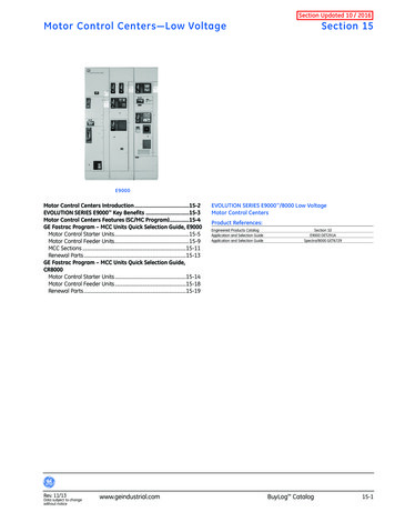
Circuit BreakersCircuit BreakersCircuit breakers are typically used as disconnect devices incombination motor control units. Circuit breakers providea manual means of energizing and de-energizing a circuit.In addition, circuit breakers provide automatic overcurrentprotection of a circuit.Siemens Sentron circuit breakers are available with ampereratings up to 2000 amps. The Sentron series is also available ina digital version, referred to as Sensitrip III. Sensitrip III circuitbreakers utilize a microcomputer which makes it possible tocustomize overcurrent protection which is matched exactly tothe loads of an electrical system.40
Circuit Breaker RatingsThere are two types of circuit breakers that are typically usedin motor control centers. Thermal-magnetic circuit breakershave both overload and instantaneous trip features. When anoverload condition exists, the excess current generates heat,which is detected in the circuit breaker. After a short period oftime, depending on the rating of the breaker and the amount ofoverload, the breaker will trip, disconnecting the load from thevoltage source. If a short circuit occurs, the breaker respondsinstantaneously to the fault current and disconnects the circuit.This type of circuit breaker is used in applications where amotor starter is not used, such as a main disconnect for theMCC or a feeder tap unit. Thermal-magnetic circuit breakers arenot used in conjuction with a motor starter.Instantaneous trip-only circuit breakers are also referred toas magnetic only or Type ETI circuit breakers. Type ETI circuitbreakers provide short circuit protection, but they do notprovide overload protection. Type ETI circuit breakers arecommonly used in combination motor control units where amotor starter, such as the Furnas ESP100, provides overloadprotection. ETI trip ranges are selected to meet maximumsettings per NEC table 430.52 and Article 430.52(C)(3). Theinstantaneous trip-only circuit breaker is factory set at the LOWposition. In accordance with the National Electical Code ,the setting on an instantaneous trip circuit breaker may beincreased over 800%, but cannot be increased over 1300% offull load amps for a NEMA B motor.NEC and National Electrical Code are registered trademarks of theNational Fire Protection Association.41
Other Types of Units in MCCsSiemens motor control centers may include solid-state motorcontrol devices, such as reduced-voltage soft-start controllers,variable frequency drives (VFD), and programmable logiccontrollers (PLCs). In addition, power meters can be used tomeasure real-time RMS values of phase currents, phase andline voltages, power usage, power factor, KW, frequency, andpeak demand.42
Reduced-VoltageSoft-Start ControllersReduced-voltage soft-start motor-starting controls, such as theSIRIUS or SIKOSTART reduced-voltage controllers, providesa smooth start while minimizing the high starting current andtorque associated with across-the-line motor starting. SIRIUScontrollers are available in models that will handle up to 60 HPat 460 volts and 75 HP at 575 volts. SIKOSTART are available inmodels that will handle up to 800 HP at 460 volts and1000 HPat 575 volts.Variable Frequency DrivesVariable frequency drives are also referred to as AC drives. Atypical AC drive receives 480 VAC, three-phase, 60 Hz inputpower which is used to start and stop a motor and control theoperation of the motor throughout the speed range. A fewfeatures of Siemens AC drives include serial communication,DC injection braking, flux current control, vector control, pulsedresistor braking, and drive and motor protection. Siemens ACdrives up to 250 HP at 480 VAC are available in MCCs.43
PLCsPLCs consist of input modules or points, a central processingunit (CPU), and output modules or points. An input to a PLCmay come from a variety of digital or analog signals fromvarious field devices. The PLC converts the input signal intoa logic signal that can be used by the CPU. Output modulesconvert control signals from the CPU into a digital or analogsignal that can be used to control various field devices, suchas a motor starter, an AC drive, or a reduced- voltage soft-startstarter.Digital MeteringDigital metering provides a highly accurate measure of currentand power in industrial applications. Meters, such as theSiemens 9200, can replace multiple analog meters and havecommunication capabilities through the Siemens ACCESS system.44
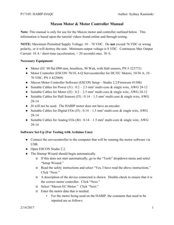
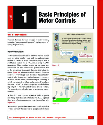
Other UnitsThere are other units that end up in MCCs such as relay panels,panelboards, and feeder-tap units. A feeder-tap unit, such asthe one shown in the following illustration, is typically used tosupply power to non-motor loads located downstream of themotor control center.UL MarksA motor control center has two UL marks. One is for thestructure and bus, and one for each control unit. Some MCCsmay contain special sections or units that have not been ULtested and therefore may not be able to carry the UL mark.Some municipalities may not allow devices that do not carry theUL mark.45
Review 41.Class provides the highest level ofoverload protection.2.The ESP100 trips within seconds of lossof one of the power-supply phases.3.A size 5 controller is rated for HP.4.Which of the following devices can be used in aSiemens motor control center?a.b.c.d.e.f.5.46reduced-voltage startervariable frequency drivePLCSAMMSdigital meteringall of the aboveand are Siemens tradenames for a reduced-voltage soft-start controller.
2. The maximum shipping width of a motor control center is _ inches. 3. Which of the following illustrates proper NEMA phase arrangement, as viewed from the front? 4. A distinguishing feature of motor control centers from panelboards is that motor control centers _ . a. principally contain combination motor control units b.