Transcription
XPH 35-4DXPH 35-4TOperating ManualXPH Series Dualand Triple Output35V 4A DCPower Supplywww.programmablepower.com
About XantrexXantrex Technology Inc. is a world-leading supplier of advanced power electronics and controlswith products from 50 watt mobile units to one MW utility-scale systems for wind, solar, batteries,fuel cells, microturbines, and backup power applications in both grid-connected and stand-alonesystems. Xantrex products include inverters, battery chargers, programmable power supplies,and variable speed drives that convert, supply, control, clean, and distribute electrical power.TrademarksXPH series is a trademark of Xantrex International. Xantrex is a registered trademark of XantrexInternational.Other trademarks, registered trademarks, and product names are the property of their respectiveowners and are used herein for identification purposes only.Notice of Copyright Xantrex International. All rights reserved.DisclaimerUNLESS SPECIFICALLY AGREED TO IN WRITING, XANTREX TECHNOLOGY INC.(“XANTREX”)(a)MAKES NO WARRANTY AS TO THE ACCURACY, SUFFICIENCY OR SUITABILITY OFANY TECHNICAL OR OTHER INFORMATION PROVIDED IN ITS MANUALS OR OTHERDOCUMENTATION.(b)ASSUMES NO RESPONSIBILITY OR LIABILITY FOR LOSS OR DAMAGE, WHETHERDIRECT, INDIRECT, CONSEQUENTIAL OR INCIDENTAL, WHICH MIGHT ARISE OUTOF THE USE OF SUCH INFORMATION. THE USE OF ANY SUCH INFORMATION WILLBE ENTIRELY AT THE USER’S RISK.Date and RevisionApril 2008 – Revision 4Part Number975-0101-01-04Contact InformationTelephone: 1-800-733-5427 (toll free in North America)1-858-450-0085 rammablepower.com1
Table of tionConnectionsOperation - Main OutputsOperation - Auxiliary OutputOperation - ions en ment - Sorties principalesFonctionnement – Sortie AuxiliaireFonctionnement - nleitung auf DeutschSicherheitInstallationAnschlüsseBetrieb - HauptausgängeBetrieb – HilfsausgangBetrieb - AllgemeinWartung18191920212122Istruzioni in mento - Uscite principaliFunzionamento – Uscita AusiliariaFunzionamento - GeneraleManutenzione23242425262627Instrucciones en EspañolSeguridadInstalaciónConexionesOperación - Salidas PrincipalesOperación – Salida AuxiliarOperación - GeneralMantenimiento28292930313132Warranty Information332
IntroductionThe XPH 35-4D and XPH 35-4Tv provide high levels of power (up to 305 watts) in a compact andattractive case style.High resolution controls allow precise setting of voltage and current levels which are indicated onaccurate and legible digital meters.Excellent line and load regulation are matched by low noise and good transient response. Highpower efficiency ensures that the unit remains cool without any fan noise.The XPH 35-4D has two independent and isolated outputs each with a 0 to 35V, 0 to 4Acapability. The outputs operate in constant voltage or constant current mode with automatic crossover and mode indication. Each output has its own on-off switch. Where higher voltages orcurrents are required the outputs can be wired in either series or parallel to provide voltages up to70 volts or currents up to 8 Amps.The XPH 35-4T has, in addition, an Auxiliary ‘logic voltage’ output with a 5A current capability. Toreflect the increasing usage of low-voltage logic devices, this output can be preset between1.5 volts and 5 volts via a front panel control.The total power capability is 280 watts for the dual supply and 305 watts for the triple.The XPH series incorporates separate digital voltage and current meters on each main output.The meters use bright 14mm (0·56”) LED displays and have an update rate of 4 per secondproviding near instantaneous response. Simultaneous metering of voltage and current providesaccurate information “at a glance” and avoids any possibility of misinterpretation. When an outputswitch is set to “off”, the current limit setting is displayed enabling conditions to be set before theload is connected. With the right-hand main output off, the right-hand meters can be used tomomentarily display the preset Auxiliary voltage and current limit.The XPH series has been designed to meet the stringent requirements of relevant IEC standardsfor safety and EMC, including harmonics emissions. All outputs are intrinsically short circuit proof,and are protected against external voltages and reverse currents.SpecificationMAIN OUTPUTSVoltage Range:0V to 35V minimum.Current Range:0A to 4A minimum.Output Voltage Setting:By coarse and fine controls.Output Current Setting:By single logarithmic control.Operating Mode:Constant voltage or constant current with automatic cross-over.Output Switch:Electronic. Preset voltage and current displayed when off.Output Terminals:Universal 4mm safety binding posts on 19mm (0·75”) pitch.Output Impedance:Typically 5mΩ in constant voltage mode.Typically 50kΩ in constant current mode.Output Protection:Output will withstand up to 40V forward voltage.Reverse protection by diode clamp for reverse currents up to 3A.Load Regulation: 0·01% of maximum output for 90% load change.Line Regulation: 0·01% of maximum output for 10% line change.Ripple & Noise(20MHz bandwidth):Typically 2mVrms, 10mVpk-pk (CV mode).3
Transient Response: 200µs to within 50mV of set level for 90% load change.Temperature Coefficient:Typically 100ppm/ C.Status Indication:Output on lamp. Constant current mode lamp.METER SPECIFICATIONS (Main Outputs)Meter Types:Dual 3 digit meters with 14mm (0·56") LEDs. Reading rate 4 Hz.Meter Resolutions:100mV, 10mA.Meter Accuracies:Voltage 0.3% of reading 1 digit,Current 0.6% of reading 1 digit.AUXILIARY LOGIC OUTPUT (XPH 35-4T only)Voltage:Variable 1·5V to 5V by front panel control.Meter Voltage Accuracy:0·3% 1 digitCurrent Limit:5A minimum.Output Protection:Output will withstand up to 7V forward voltage.Diode clamp reverse protection for currents up to 3A.Load Regulation: 0·5% for 90% load change.Line Regulation: 0·1% for 10% line voltage change.Ripple & Noise(20MHz bandwidth):Typically 2mVrms, 10mVpk-pk (CV mode).Transient Response:Typically 200µs to within 50mV of set level for 90% load change.Temperature Coefficient:Typically 100ppm/ºC.Status Indication:UNREG lamp.GENERAL4AC Input:110V - 240V AC 10%, 50/60Hz. Installation Category II.Power Consumption:500VA max.Operating Range: 5ºC to 40ºC, 20% to 80% RH.Storage Range: 40ºC to 70ºC.Environmental:Indoor use at altitudes up to 2000m, Pollution Degree 2.Safety:Complies with EN61010-1.EMC:Complies with EN61326.Size:260 x 160 x 320mm (WxHxD).Weight:4·3kg
EMCThis instrument has been designed to meet the requirements of the EMC Directive 89/336/EEC.Compliance was demonstrated by meeting the test limits of the following standards:EmissionsEN61326 (1998) EMC product standard for Electrical Equipment for Measurement, Control andLaboratory Use. Test limits used were:a)Radiated: Class Bb)Conducted: Class Bc)Harmonics: EN61000-3-2 (2000) Class A; the instrument is Class A by product category.ImmunityEN61326 (1998) EMC product standard for Electrical Equipment for Measurement, Control andLaboratory Use.Test methods, limits and performance achieved were:a)b)c)d)e)f)EN61000-4-2 (1995) Electrostatic Discharge : 4kV air, 4kV contact, Performance A.EN61000-4-3 (1997) Electromagnetic Field, 3V/m, 80% AM at 1kHz, Performance B.EN61000-4-11 (1994) Voltage Interrupt, 1 cycle, 100%, Performance B.EN61000-4-4 (1995) Fast Transient, 1kV peak (AC line), 0.5kV peak (DC Outputs),Performance B.EN61000-4-5 (1995) Surge, 0.5kV (line to line), 1kV (line to ground), Performance B.EN61000-4-6 (1996) Conducted RF, 3V, 80% AM at 1kHz (AC line only; DC Outputconnections 3m not tested), Performance A.According to EN61326 the definitions of performance criteria are:Performance criterion A: ‘During test normal performance within the specification limits.’Performance criterion B: ‘During test, temporary degradation, or loss of function orperformance which is self-recovering’.Performance criterion C: ‘During test, temporary degradation, or loss of function orperformance which requires operator intervention or system reset occurs.’Where Performance B is stated it is because DC Output regulation may deviate beyondSpecification limits under the test conditions. However, the possible deviations are still small andunlikely to be a problem in practice.Note that if operation in a high RF field is unavoidable it is good practice to connect the PSU tothe target system using screened leads which have been passed (together) through an absorbingferrite sleeve fitted close to the PSU terminals.CautionsTo ensure continued compliance with the EMC directive observe the following precautions:a) after opening the case for any reason ensure that all signal and ground connections areremade correctly and that case screws are correctly refitted and tightened.b) In the event of part replacement becoming necessary, only use components of an identicaltype, see the Service Manual.5
SafetyThis power supply is a Safety Class I instrument according to IEC classification and has beendesigned to meet the requirements of EN61010-1 (Safety Requirements for Electrical Equipmentfor Measurement, Control and Laboratory Use). It is an Installation Category II instrumentintended for operation from a normal single phase supply.This instrument has been tested in accordance with EN61010-1 and has been supplied in a safecondition. This instruction manual contains some information and warnings which have to befollowed by the user to ensure safe operation and to retain the instrument in a safe condition.This instrument has been designed for indoor use in a Pollution Degree 2 environment in thetemperature range 5 C to 40 C, 20% - 80% RH (non-condensing). It may occasionally besubjected to temperatures between 5 C and –10 C without degradation of its safety. Do notoperate while condensation is present.Use of this instrument in a manner not specified by these instructions may impair the safetyprotection provided. Do not operate the instrument outside its rated supply voltages orenvironmental range.WARNING! THIS INSTRUMENT MUST BE EARTHEDAny interruption of the mains earth conductor inside or outside the instrument will make theinstrument dangerous. Intentional interruption is prohibited. The protective action must not benegated by the use of an extension cord without a protective conductor.When the instrument is connected to its supply, terminals may be live and opening the covers orremoval of parts (except those to which access can be gained by hand) is likely to expose liveparts. The apparatus shall be disconnected from all voltage sources before it is opened for anyadjustment, replacement, maintenance or repair. Capacitors inside the power supply may still becharged even if the power supply has been disconnected from all voltage sources but will besafely discharged about 10 minutes after switching off power.Any adjustment, maintenance and repair of the opened instrument under voltage shall be avoidedas far as possible and, if inevitable, shall be carried out only by a skilled person who is aware ofthe hazard involved.If the instrument is clearly defective, has been subject to mechanical damage, excessive moistureor chemical corrosion the safety protection may be impaired and the apparatus should bewithdrawn from use and returned for checking and repair.Make sure that only fuses with the required rated current and of the specified type are used forreplacement. The use of makeshift fuses and the short-circuiting of fuse holders is prohibited.Do not wet the instrument when cleaning it.The following symbols are used on the instrument and in this manual:Earth (ground) terminal.mains supply OFF.lmains supply ON.alternating current (ac)direct current (dc)6
InstallationMains Operating VoltageThis instrument has a universal input range and will operate from a nominal 115V or 230V mainssupply without adjustment. Check that the local supply meets the AC Input requirement given inthe Specification.Mains LeadWhen a three core mains lead with bare ends is provided this should be connected as follows:BROWN-MAINS LIVEBLUE-MAINS NEUTRALGREEN/YELLOW-EARTHSafety Earth SymbolWhen fitting a fused plug a 5 amp fuse should be fitted inside the plug. As the colours of thewires in the mains lead of this apparatus may not correspond with the coloured markingsidentifying the terminals in your plug proceed as follows:The wire which is coloured green-and-yellow must be connected to the terminal in the plug whichis marked by the letter E or by the safety earth symbol shown above or coloured green or greenand-yellow.The wire which is coloured blue must be connected to the terminal which is marked with the letterN or coloured black.The wire which is coloured brown must be connected to the terminal which is marked with theletter L or coloured red.WARNING! THIS INSTRUMENT MUST BE EARTHED.Any interruption of the mains earth conductor inside or outside the instrument will make theinstrument dangerous. Intentional interruption is prohibited.ConnectionsAll connections are made from the front panel.The load should be connected to the positive (red) and negative (black) terminals markedOUTPUT.The terminal markedis connected to the chassis and safety earth ground.7
Operation - Main OutputsThe operation of both main outputs is identical; the following description applies to both.Setting Up the OutputWith the POWER switch on (l) and theoutput OFF the output voltage and current limit canbe accurately preset using the VOLTAGE and CURRENT controls; the left-hand meter shows theset voltage and the right-hand meter shows the set maximum current.When the output switch is switched ON, thelamp lights; the left-hand meter now shows theactual voltage and the right-hand meter the actual load current.Constant VoltageThe output voltage is adjusted using the coarse and fine VOLTAGE controls; the CURRENTcontrol sets the maximum current that can be supplied.Constant CurrentIf the load resistance is low enough such that, at the output voltage set, a current greater than thecurrent limit setting would flow, the power supply will automatically move into constant currentoperation. The current output is adjusted by the CURRENT control and the VOLTAGE controlsset the maximum voltage that can be generated.The CC lamp lights to show constant current mode.Instantaneous Current OutputThe current limit control can be set to limit the continuous output current to levels down to 10mA.However, in common with all precision bench power supplies, a capacitor is connected across theoutput to maintain stability and good transient response. This capacitor charges to the outputvoltage and short-circuiting of the output will produce a current pulse as the capacitor dischargeswhich is independent of the current limit setting.ProtectionThe output has intrinsic short-circuit protection and is protected from reverse voltages by a diode;the continuous reverse current must not exceed 3 Amps, although transients can be much higher.The output is protected against externally applied forward voltages of up to 40V.8
Operation - Auxiliary OutputOutput VoltageThe output voltage can be set between 1·5V and 5·0V using the front panel rotary adjustmentbeside the centre terminals. With the right-hand main output OFF, pressing the SHOW AUXPRESET button will display the AUX output voltage and current limit on the right-hand meters.Current LimitThe output will go into current limit at between 5A and 6A; the UNREG lamp lights in thiscondition.ProtectionThe output has intrinsic short-circuit protection and is protected from reverse voltages by a diode;the continuous reverse current must not exceed 3 Amps, although transients can be much higher.The output is protected against externally applied forward voltages of up to 7V.Operation - GeneralConnection to the LoadThe load should be connected to the positive (red) and negative (black) output terminals. Bothare fully floating and either can be connected to ground.Series or Parallel Connection with Other OutputsThe outputs of the power supply are fully floating and may be used in series with other powersupply units to generate high DC voltages up to 300V DC.The maximum permissible voltage between any terminal and earth ground ( ) is 300VDC; themaximum permissible voltage between either terminal of one output and any terminal of anotheroutput on the same supply is also 300VDC.WARNING! Such voltages are exceedingly hazardous and great care should be taken to shieldthe output terminals for such use. On no account should the output terminals be touched whenthe unit is switched on under such use. All connections to the terminals must be made with thepower switched off on all units.It should be noted that the unit can only source current and cannot sink it, thus units cannot beseries connected in anti-phase.The unit can be connected in parallel with others to produce higher currents. Where several unitsare connected in parallel, the output voltage will be equal to that of the unit with the highest outputvoltage setting until the current drawn exceeds its current limit setting, upon which the output willfall to that of the next highest setting, and so on. In constant current mode, units can beconnected in parallel to provide a current equal to the sum of the current limit settings.VentilationThe power supply is very efficient but nevertheless can generate significant heat at full power.The supply relies on convection cooling only and it is therefore important that ventilation is neverrestricted if performance and safety are to be maintained.9
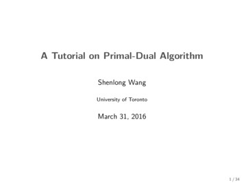
CalibrationAllow at least 5 minutes warm-up before commencing calibration.Access to Calibration AdjustmentsAll adjustments are on the front panel control board; all the trimmers are adjusted from thereverse side of the board through holes in the board. To gain access to the board it is necessaryto remove the top cover.WARNING!When the instrument is connected to its supply the removal of covers is likely to expose live parts.The instrument should be disconnected from all voltage sources before it is opened for anyadjustment, replacement, maintenance or repair. Capacitors inside the power supply may still becharged even if the power supply has been disconnected from all voltage sources but will besafely discharged about 5 minutes after switching off power.Any adjustment, maintenance and repair of the opened instrument under voltage shall be avoidedas far as possible and, if inevitable, shall be carried out only by a skilled person who is aware ofthe hazard involved.Remove the 6 side screws and the front handle screw to release the top cover.Component adjustment references are given as Channel A/ Channel B, e.g. VR5/VR105;Channel A is the left-hand output.Control pcb calibration points (viewed from rear)Equipment RequiredA 5½ digit multimeter with better than 0·05% accuracy on dc volts and better than 0·1% accuracyon dc current (to 5A); alternatively use a precision shunt for current measurement.Rheostat or other high power load arrangement to provide up to 5A load at 35V.Voltage CalibrationConnect the DMM (set to Volts) across the output. Set voltage and current controls to minimum.Switch output ON (Check LED is on) and check for a reading of 00·0V 0·1V on the Volts displayand DMM; check the Amps display reads 0·00 0·01A.Set voltage and current controls to maximum. Adjust VR5/VR105 (maximum output volts) for areading of 35·16V to 35·24V on the DMM. Adjust VR6/VR106 (measured output volts) until theVolts display matches the reading on the external DMM.Switch output OFF. Adjust VR10/110 (preset volts) until the Volts display shows 35·2.10
Current CalibrationSwitch output OFF. Set output voltage to nominally 2V. Set current control to minimum. Connectthe DMM (set to Amps) and load in series across the output. Switch output ON.Adjust VR8/108 (offset compensation of current control error amp) for a reading of 0·003A ·001A on the DMM. Check that the CC LED is ON.Increase voltage controls and current control to maximum. Adjust load until the DMM reads 4·00A 0·02A. Adjust VR7/107 (measured output current) until the Amps display matches the DMMreading.Reduce load until the CC LED is ON. Adjust VR4/104 (maximum output current) until the Ampsdisplay shows 4·05.Voltage RegulationConnect the DMM (set to Volts) across the output, no load, output ON.Adjust voltage controls for a reading of 18.xxxx on the DMM; note exact reading.Connect load, set current control to maximum and adjust load for 4A output current. Note that theDMM should be connected at the ‘back’ of the output terminals, closest to the internal senseconnection, and the load plugged in to the 4mm sockets of the terminals. Adjust VR9/109(differential voltage gain) until the external DMM matches the previous reading exactly.1.5V/5V OutputConnect the DMM to the output. Use the front panel control to adjust the output to 5.0x Volts.With the right-hand Main output OFF, press the SHOW AUX PRESET button to display the AUXOUT voltage; adjust VR1 on the 1.5V/5V pcb until the display reads 5.0V.Connect the DMM (set to Amps) and load in series across the output. Adjust load until theUNREG LED comes ON. Check that the DMM reads 5 Amps.Connect the DMM (set to Volts) in parallel with the load across the output. Adjust load until theUNREG LED just goes off. Check that the DMM reads the same as in the 5V check above, 0·025V.11
MaintenanceThe Manufacturers or their agents overseas will provide repair for any unit developing a fault.Where owner wish to undertake their own maintenance work, this should only be done by skilledpersonnel in conjunction with the service manual which may be purchased directly from theManufacturers or their agents overseas.FuseThe correct fuse type is:10 Amp 250V HBC time-lag(T), 5 x 20mm.Note that the main function of the fuse is to make the instrument safe and limit damage in theevent of failure of one of the switching devices. If a fuse fails it is therefore very likely that thereplacement will also blow, because the supply has developed a fault; in such circumstances theinstrument will need to be returned to the manufacturer for service.Make sure that only fuses of the required rated current and specified type are used forreplacement. The use of makeshift fuses and the short-circuiting of fuse-holders is prohibited.To replace a fuse, first disconnect the instrument from the AC supply. Remove the 7 coversecuring screws and lift off the cover. Replace the fuse with one of the correct type and refit thecover.CleaningIf the PSU requires cleaning use a cloth that is only lightly dampened with water or a milddetergent. Polish the display window with a soft dry cloth.WARNING! TO AVOID ELECTRIC SHOCK, OR DAMAGE TO THE PSU, NEVER ALLOWWATER TO GET INSIDE THE CASE. TO AVOID DAMAGE TO THE CASE OR DISPLAYWINDOW NEVER CLEAN WITH SOLVENTS.12
SécuritéCet instrument est de Classe de sécurité 1 suivant la classification IEC et il a été construit poursatisfaire aux impératifs EN61010-1 (impératifs de sécurité pour le matériel électrique en vue demesure, commande et utilisation en laboratoire). Il s'agit d'un instrument d'installation Catégorie IIdevant être exploité depuis une alimentation monophasée habituelle.Cet instrument a été soumis à des essais conformément à EN61010-1 et il a été fourni en toutétat de sécurité. Ce manuel d'instructions contient des informations et avertissements qui doiventêtre suivis par l'utilisateur afin d'assurer un fonctionnement de toute sécurité et de conserverl'instrument dans un état de bonne sécurité.Cet instrument a été conçu pour être utilisé en interne dans un environnement de pollutionDegré 2, plage de températures 5 C à 40 C, 20% - 80% HR (sans condensation). Il peut êtresoumis de temps à autre à des températures comprises entre 5 C et –10 C sans dégradationde sa sécurité. Ne pas l'utiliser lorsqu'il y a de la condensation.Toute utilisation de cet instrument de manière non spécifiée par ces instructions risque d'affecterla protection de sécurité conférée. Ne pas utiliser l'instrument à l'extérieur des tensionsd'alimentation nominales ou de la gamme des conditions ambiantes spécifiées.AVERTISSEMENT! CET INSTRUMENT DOIT ETRE RELIE A LA TERREToute interruption du conducteur de terre secteur à l'intérieur ou à l'extérieur de l'instrumentrendra l'instrument dangereux. Il est absolument interdit d'effectuer une interruption à dessein. Nepas utiliser de cordon de prolongation sans conducteur de protection, car ceci annulerait sacapacité de protection.Lorsque l'instrument est relié au secteur, il est possible que les bornes soient sous tension et parsuite, l'ouverture des couvercles ou la dépose de pièces (à l'exception de celles auxquelles onpeut accéder manuellement) risque de mettre à découvert des pièces sous tension. Il fautdébrancher ke cordon secteur de l'appareil avant de l'ouvrir pour effectuer des réglages,remplacements, travaux d'entretien ou de réparations. Les condensateurs qui se trouvent dans lebloc d'alimentation risquent de rester chargés, même si le bloc d'alimentation a été déconnectéde toutes les sources de tension, mais ils se déchargeront en toute sécurité environ 10 minutesaprès extinction de l'alimentation.Eviter dans la mesure du possible d'effectuer des réglages, travaux de réparations ou d'entretienlorsque l'instrument ouvert est branché au secteur, mais si c'est absolument nécessaire, seul untechnicien compétent au courant des risques encourus doit effectuer ce genre de travaux.S'il est évident que l'instrument est défectueux, qu'il a été soumis à des dégâts mécaniques, àune humidité excessive ou à une corrosion chimique, la protection de sécurité sera amoindrie et ilfaut retirer l'appareil, afin qu'il ne soit pas utilisé, et le renvoyer en vue de vérifications et deréparations.Remplacer les fusibles uniquement par des fusibles d'intensité nominale requise et de typespécifié. Il est interdit d'utiliser des fusibles bricolés et de court-circuiter des porte-fusibles.Eviter de mouiller l'instrument lors de son nettoyage.Les symboles suivants se trouvent sur l'instrument, ainsi que dans ce manuel.Borne de terre (masse)lalimentation secteur ON (allumée)courant continu (c.c.)alimentation secteur OFF (éteinte)courant alternatif (c.a.)13
InstallationTension d’utilisation secteurCet instrument a une plage d'entrée universelle et il fonctionne sur une alimentation secteur de115 V ou de 230 V, tension nominale, sans ajustement aucun. Vérifier que l'alimentation localesatisfait aux impératifs d'entrée c.a. indiqués aux Caractéristiques techniques.Câble secteurRelier de la manière suivante tout câble secteur à trois conducteurs à fils nus:MARRON-SECTEUR SOUS TENSIONBLEU-SECTEUR NEUTREVERT/JAUNE-TERRESymbole Terre de protectionLors du montage d'une fiche à fusible, mettre un fusible de 5 A à l'intérieur de la fiche. Il estpossible que les couleurs des fils du câble secteur de cet appareil ne correspondent pas auxmarques de couleur d'identification des bornes de la fiche, et par suite, il est recommandé deprocéder de la manière suivante:Relier le fil vert et jaune à la borne de la fiche désignée par la lettre E ou par le symbole Terrede protection indiqué ci-dessus, ou qui est en vert, ou en vert et jaune.Relier le fil bleu à la borne désignée par la lettre N, ou qui est en noir.Relier le fil marron à la borne désignée par la lettre L, ou qui est en rouge.AVERTISSEMENT! CET INSTRUMENT DOIT ETRE RELIE A LA TERREToute interruption du conducteur de terre secteur à l'intérieur ou à l'extérieur de l'instrumentrendra l'instrument dangereux. Il est absolument interdit d'effectuer une interruption à dessein.ConnexionsToutes les connexions sont effectuées au panneau avant.Relier la charge aux bornes positive (rouge) et négative (noire) marquées OUTPUT (Sortie).La borne désignée14est reliée au châssis et à la terre de protection.
Fonctionnement - Sorties principalesLe fonctionnement des deux sorties principales est identique; la description suivante s’appliqueaux deux.Réglage de la sortieLorsque l’interrupteur POWER (alimentation) est en position (l) et la sortieest en positionOFF (éteinte), il est possible de régler avec précision la limite de tension et de courant de sortieau moyen des commandes VOLTAGE (Tension) et CURRENT (Courant); l’appareil de mesuregauche indique la tension réglée et l’appareil droit le courant maximum réglé.Lorsque le commutateur de sortieest en position ON (marche), le témoin s’allume; l’appareilde mesure gauche indique alors la tension véritable et l’appareil droit le courant de chargevéritable.Tension constanteLes commandes VOLTAGE de réglage grossier et de précision permettent d’ajuster la tension desortie; la commande CURRENT règle le courant maximum qui peut être fourni.Courant constantSi la résistance de charge est suffisamment basse qu’un courant supérieur au réglage de limitede courant puisse passer pour la tension de sortie réglée, l’alimentation passeraautomatiquement en mode de fonctionnement de courant constant. La commande CURRENTajuste le courant de sortie et les commandes VOLTAGE règlent la tension maximale qui peut êtreengendrée. Le témoin CC s’allume pour indiquer le mode de courant constant.Sortie de courant instantanéeIl est possible de régler la commande de limite de courant pour limiter le courant de sortie continuà des niveaux aussi bas que 10 mA. Toutefois, ainsi que c’est le cas de toutes les alimentationsde précision sur banc, un condensateur est relié aux bornes de la sortie, afin de maintenir lastabilité, ainsi qu’une bonne réponse transitoire. Ce condensateur se charge jusqu’à la tension desortie, et le court-c
Operating Mode: Constant voltage or constant current with automatic cross-over. Output Switch: Electronic. Preset voltage and current displayed when off. Output Terminals: Universal 4mm safety binding posts on 19mm (0·75") pitch. Output Impedance: Typically 5mΩ in constant voltage mode. Typically 50kΩ in constant current mode.