Transcription
sE87010-A0401-T002-A5-MCCtiastarTM Motor Control CenterPage 1 of 12Installation InstructionsJuly, 2015tiastarTM Motor Control CenterInstallation Instructions For Motor Control Center (MCC) UnitsSiemens Industry, Inc. 5300 Triangle Parkway, Norcross, GA 30092A5E33045207A
E87010-A0401-T002-A5-MCCtiastarTM Motor Control CenterHazardous voltage.Will cause death or serious injury.Always de-energize and ground the equipmentbefore maintenance. Read and understand thismanual before installing, operating or maintainingthe equipment. Maintenance should be performedonly by qualified personnel. The use of unauthorized parts in the repair of the equipment or tampering by unqualified personnel may result in dangerous conditions which may cause death or serious injury, or equipment or property damage.Follow all safety instructions contained herein.Page 2 of 12THIS EQUIPMENT CONTAINS HAZARDOUS VOLTAGES. DEATH, SERIOUS PERSONAL INJURY, OR PROPERTY DAMAGE CAN RESULT IFSAFETY INSTRUCTIONS ARE NOT FOLLOWED. ONLY QUALIFIED PERSONNEL SHOULD WORK ON OR AROUND THIS EQUIPMENTAFTER BECOMING THOROUGHLY FAMILIAR WITH ALL WARNINGS, SAFETY NOTICES, AND MAINTENANCE PROCEDURES CONTAINEDHEREIN.THE SUCCESSFUL AND SAFE OPERATION OF THIS EQUIPMENT IS DEPENDENT UPON PROPER HANDLING, INSTALLATION, OPERATIONAND MAINTENANCE.SIGNAL WORDSQUALIFIED PERSONThe signal words “DANGER”, “WARNING” and “CAUTION”used in this manual indicate the degree of hazard that may beencountered by the user. These words are defined as:For the purposes of this manual and product labels, a qualified person is one who is familiar with the installation, construction, operation or maintenance of the equipment and thehazards involved. In addition this person has the followingqualifications:DANGER - For the purpose of this manual and product labels,DANGER indicates an imminently hazardous situation which,if not avoided will result in death or serious injury.WARNING - For the purpose of this manual and productlabels, WARNING indicates a potentially hazardous situationwhich, if not avoided, could result in death or serious injury.CAUTION - For the purpose of this manual and productlabels, CAUTION indicates a potentially hazardous situationwhich, if not avoided, may result in minor or moderate injury.(a) is trained and authorized to energize, de-energize,clear, ground and tag circuits and equipment inaccordance with established safety practices.(b) is trained in the proper care and use of protectiveequipment such as rubber gloves, hard hat, safetyglasses or face shields, flash clothing, etc., inaccordance with established safety practices.(c) is trained in rendering first aid.IMPORTANTThese instructions do not purport to cover all details or variations in equipment, nor to provide for every possible contingency to be met in connectionwith installation, operation or maintenance. Should further information be desired or should particular problems arise which are not covered sufficiently for the purchaser’s purposes, the matter should be referred to the local Siemens sales office. The contents of this instruction manual shall notbecome part of or modify any prior or existing agreement, commitment or relationship. The sales contract contains the entire obligation of Siemens.The warranty contained in the contract between the parties is the sole warranty of Siemens. Any statements contained herein do not create newwarranties or modify the existing warranty.Table of Contents1. Receiving2. Removing Existing Unit3. Installing Unit4. Handle Adjustment5. Outgoing Power and Control Wiring6. Pre-operation Checks7. High Density Units8. 600A Bolted Clamp Assembly9. Wiring Fixed Mounted Units10.Recommended Tightening Torques11.Additional ResourcesSiemens Industry, Inc. 5300 Triangle Parkway, Norcross, GA 30092345677810111212A5E33045207A
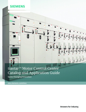
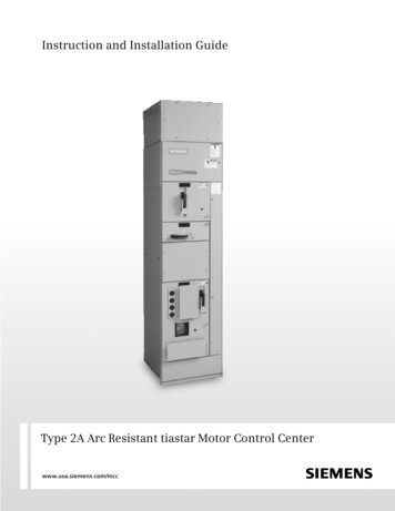
1 ReceivingE87010-A0401-T002-A5-MCCtiastarTM Motor Control CenterPage 3 of 121.1 Carefully remove all packaging material from the unit.1.2 Read the entire unit installation guide.1.3 Inspect the unit for damage.1.4 Become familiar with unit and unit support components1828483858687881) Locking latch2) Pilot device panel3) Top barrier plate4) Pilot device mounting hole(used when mounting directly to unit)5) Operating handle6) Racking lever7) Swing plate8) Terminal blockFigure 1 - Unit Components182838481) Pin-type door hinge2) Shelf bracket3) Separator angle4) Intermediate angleFigure 2 - Unit Support ComponentsIf damage or loss is discovered, file a claim with the carrier who delivered the control unit. As muchidentification as possible should accompany the claim, together with a full description of the damage.When filing a claim with the carrier, photographs of the damage are very helpful.Siemens Industry, Inc. 5300 Triangle Parkway, Norcross, GA 30092A5E33045207A
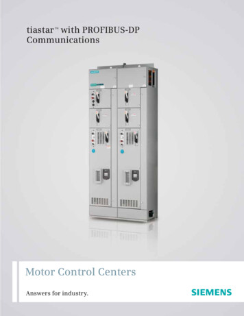
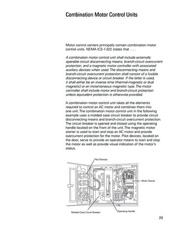
2. Removing Existing UnitE87010-A0401-T002-A5-MCCtiastarTM Motor Control CenterPage 4 of 12Recommended Tools:Flat-head screwdriverPhillips-head screwdriverMultimeter with pointed probes2.1. Put disconnect operating handle in the PARK position(See Figure 3).2.2. Unscrew latch located at the bottom of the unitRotate the latch until it disengages from theseparator angle (See Figure 4).Figure 3 - Operating Handle Positions2.3. Transfer pilot device panel from door to slot on unit.Remove panel by removing the screws located at thetop and bottom of the panel.2.4. Open vertical wireway door.2.5. Move unit to “Test” position by opening racking lever inthe top barrier plate (See Figure 6a).2.6. Disconnect control and load wiring.2.7. Remove unit by slightly tilting the front of the unitdownward and sliding it out. This is to insure thatthe unit doesn’t get caught on the shelf bracket.2.8. If rearranging units of different sizes, perform thefollowing tasks:Figure 4 - Disengaging latch2.8.1. Remove all unit support assemblies by unfastening the screws for each assembly, tilting upwardand sliding out of their holes.StabHoleCovers2.8.2. Realign support assemblies as needed.2.8.3. Include intermediate angles in all spaces (See Figure 2).2.8.4. Remove stab hole covers at appropriate heightsand replace covers on unused stab holes.Stab hole covers should be arranged so that the onlyuncovered openings are those to which a unit will beconnected (See Figure 5).Figure 5 - Stab Hole Covers2.8.4a MCCs with automatic shutters; tiastar ShutterMechanism Kit 8PG1191-2MA00 is available ifadditional shutters are needed.Siemens Industry, Inc. 5300 Triangle Parkway, Norcross, GA 30092A5E33045207A
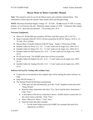
3. Installing Unit3.1. If present, remove existing door by first withdrawing itshinge pins and then closing it halfway before sliding itoff its hinges.E87010-A0401-T002-A5-MCCtiastarTM Motor Control CenterPage 5 of 123.2. Remove Intermediate angle by removing the screwwhich fastens it to the Separator Angle and tippingslightly to remove formed tab at top from slot in shelfbracket above.3.3. If necessary, install unit support assembly by insertingshelf brackets at a slight angle into the appropriateholes in the vertical bus support angle and snappinginto place. Secure support assembly with the two screwsprovided. One screw fastens the right-hand shelf bracketto the vertical bus support angle. The second screwfastens the separator angle to the left side of the structure. For additional information on unit support installation, please refer to section 8.2.3.4. If necessary, remove appropriate unit stab hole covers.3.5. Install unit door by sliding it onto the hinges while halfopen. Once on the hinges, open the door completelyand insert hinge pins.Figure 6a - Placing Unit on Support Assemblyand in test position3.6. Place plug-in unit inside of enclosure (Figure 6a).3.6.1. With the handle in the PARK position, slide unit intoplace on support assembly.3.6.2. Slightly tilt the front of the unit downwards in order toslide the back of the unit over the shelf brackets.3.6.3. Once the unit has been pushed in as far as it can go,close the racking lever in top barrier plate(Figure 6b).3.6.4. Engage locking latch at lower left of the unit to theseparator angle and tighten it using a flat-headscrewdriver (latch is shown above in Figure 4 onpage 4).Figure 6b - Closing Racking LeverSiemens Industry, Inc. 5300 Triangle Parkway, Norcross, GA 30092A5E33045207A
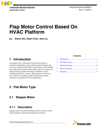
4. Handle AdjustmentNote: Additional handle adjustment information can befound in section 11E87010-A0401-T002-A5-MCCtiastarTM Motor Control CenterPage 6 of 12Recommended Tools:2 – 5/16 in. socket wrenches for adjusting unit handle4.1. Perform all disconnect operating handle adjustments4.6. Return the handle to the ON position and the diswith the unit removed from the motor control center or inconnect will turn ON. If it does not, rotate the sleevethe “Test” position (See Figure 6a).slightly clockwise and try again. Repeat this step untilthe handle assembly turns the unit ON. Then, repeat4.2. The adjustable link rod can adjust to increase or destep 4.5. Note: To perform this operation with the doorcrease its overall length by rotating the sleeve. By rotatopen it will be necessary to push down on the exposeding the sleeve clockwise the length is increased and byinterlock arm lever.rotating it counterclockwise the length is decreased.A hex nut is provided as part of the adjustable link rodand is tightened against the sleeve to prevent it fromFor Circuit Breaker Units Onlygoing out of adjustment. The hex nut must be looseand sufficiently away from the sleeve to allow it to4.7. Trip the circuit breaker and the handle should move torotate during the adjustment of the handle.a position between the ON and OFF positions. (Mostcircuit breakers can be manually tripped by pressing aNote: Always use two wrenches when loosening,red or black button on the front of the device).adjusting, or tightening the adjustable link rod.One wrench adjusts the hex sleeve while the second4.8. Move the handle down past the OFF position to resetwrench holds the hex nut.the circuit breaker. If the circuit breaker resets andcan be returned to the ON position by the handle, the4.3. The handle assembly must be adjusted to perform theadjustment has been completed and the hex nutfollowing functions:should be tightened against the sleeve. If the circuitbreaker does not reset, turn the sleeve counterclock4.4. Unit must turn ON; Unit must turn OFF; Unit must indiwise slightly and try again. Repeat this step until thecate TRIP; Unit must RESET.breaker resets. Then repeat steps 4.5 – 4.8 to verifyoperation.4.5. Operate the handle from the ON position to the OFFposition and disconnect will turn OFF.Figure 7 - Operating Handle AdjustmentSiemens Industry, Inc. 5300 Triangle Parkway, Norcross, GA 30092A5E33045207A
E87010-A0401-T002-A5-MCCtiastarTM Motor Control CenterPage 7 of 125. Outgoing Power and Control Wiring5.1. Connect power and control wires for the unit withthe unit stabs disengaged from the vertical bus.5.2. Wiring between control units is pulled through the vertical wireway at the right side of the section. These wirescan be fastened with the wireform wireties provided.Route wiring to control units in other sections throughthe horizontal wireways.5.3. When load cable conduit is in the bottom of a MotorControl Center, additional room for pulling cable maybe obtained by removing bottom plug-in units.5.4. For rear units of back-to-back Motor Control Centers,connect motor T1 to terminal unit T3 and motor T3 toterminal unit T1 in order to obtain the same motor rotation as for motors controlled by front units.6. Pre-operation ChecksBefore energizing and operating the motor control center,perform the following checks6.1. Operate all magnetic devices by hand to be sure thatall parts operate freely. Check all interlocks for propercontact operation6.2. Current transformers for customer remote devices arehipped with their secondaries shorted out. Be sure allsuch shunts are removed when the metering circuits arecompleted.6.3. Be sure that each motor is connected with the properstarter6.4. Check the overload setting or overload heater elementagainst the full load current shown on the nameplate ofeach motor.6.5. Check all heater elements to insure that they areproperly installed.6.6. Check all timers for proper time interval setting andcontact operations.6.7. If instantaneous trip circuit breakers are used,adjust as follows:6.7.1. Determine motor full load current from the motornameplate data. Use screwdriver to set indicatoron adjustment screw to the appropriate position.6.7.2. For maximum protection, the trip position shouldbe set as low as possible. Turn the adjustmentscrew counterclockwise to successively lowerpositions until the breaker trips on motor starting.After this position is determined, turn the adjustment screw clockwise to the next higher settingfor normal operation.If the breaker does not trip at the lowest setting,leave the indicator at this setting.6.7.3. If tripping occurs at highest setting; re-checkmotor nameplate information, then check voltageand load with peak reading ammeter to locateproblem.6.8. If fusible disconnect type starters are used, check forproper fuse size. Fuse size should not exceed 150%FLA for RK5 and 300% FLA for Type J.6.9. Clean the motor control center and be sure that allextraneous material has been removed.6.10. Check the torque value of each connection.Factory connections may loosen during shipmentstorage. It is of utmost importance to inspectall connections and bolted joints for tightnessPRIOR TO energizing the equipment. Follow torquerequirements of individual components formotor / load connections.6.11. Close all access plates and doors before the motorcontrol center is energized.6.12. Jog motors to determine proper rotation.Siemens Industry, Inc. 5300 Triangle Parkway, Norcross, GA 30092A5E33045207A
7 High Density UnitsCoil Removal1. For easy coil replacement, remove the unit from thestructure.2. Loosen screw “A” which secures the cover.3. Rotate the cover as shown in Figure 8 around the pivotpoint.4. Disconnect wiring to coil.5. Remove coil through top of unit.E87010-A0401-T002-A5-MCCtiastarTM Motor Control CenterPage 8 of 12Arc Cover Access SlotsWithdraw the unit for access to the arc cover screws through theslots in the unit bottom plate as shown in Figure 10.Screw “A”Figure 10Hinge Installation1. Remove the existing hinge (if present) in the 6 in space.See Figure 11.2. Install the unit support bracket per “Adding To A Blank UnitSpace” on page 4.3. Locate and install the new hinge with the two mounting screws.4. Install the door using two new hinge pins supplied with the unit.Figure 8Terminal Block Swing Plate1. To wire the unit, rotate the terminal block swing plate asshown in Figure 9.2. Route the wires from the vertical wireway into the unitbehind the right unit side angle.TerminalBlockSwingPlateFigure 11Figure 9Unit Access For Maintenance1. Remove the unit from the structure.2. Loosen screw “B” shown in Figure 12.3. Lift the handle bracket and pull forward to disengage.4. Rotate the left side of the unit open as shown in Figure 12.5. When closing the unit, the handle must be in the OFF position.Screw “B”Handle BracketFigure 12Siemens Industry, Inc. 5300 Triangle Parkway, Norcross, GA 30092A5E33045207A
E87010-A0401-T002-A5-MCCtiastarTM Motor Control CenterPage 9 of 12Section 7 continued6” Unit Access for Maintenance 150-250A Circuit Breaker UnitsHandle MechanismScrew “D”Unit Access for Maintenance1.2.3.4.Remove unit from structureRemove screws “D” shown in figure 13- qty 4Remove the handle mechanism from the unitWhen reinserting the handle mechanism, the handle must be in the OFF position.Siemens Industry, Inc. 5300 Triangle Parkway, Norcross, GA 30092A5E33045207A
8. 400A and 600A Bolted Clamp AssemblyE87010-A0401-T002-A5-MCCtiastarTM Motor Control CenterPage 10 of 12The clamp assembly is required for replacement or assembly of 400A and 600A circuit breakers or disconnect switchesthat are mounted directly to the vertical bus.ABCDEFGHIJK- Vertical Bus Bar- Carriage Bolt- Flat Washer- 3/8” Standard Hex Nut- Clamping Spring- Bar- Tie Bar- Carriage Bolt- Flat Washer- 3/8” Standard Hex Nut- Riser from breaker / disconnectAFECBDGHClamp Removal1. Refer to Figure 14 for parts identification.Loosen nut J and remove bolt H, washer I, and nut from riser.KIJFigure 142. Loosen nut D and remove bolt B, washer C, and nut fromthe clamp assembly.3. Remove tie bar and clamp assembly simultaneously.4. Repeat steps 1 - 4 for each phase.Clamp AssemblyNotice: To be installed on 600A or 800A vertical bus only.1. Connect tie bar riser by sliding bolt H through tie bar and riser.Fasten with washer I and torque nut J and bolt H securing to280 in-lbs.2. Loosely assemble the clamp assembly, making sure thatclamp spring E will compress against bar F, when the the boltis drawn tight.3. Slide carriage bolt B through one side of the clamp assemblyand tie bar until it portrudes therough the other side of theclamp assembly. Fasten with washer C and torque nut D tobolt B securing to 280 in-lbs.Figure 154. Repeat steps 1 - 3 for all phases.5. Refer to Figure 15 for completed assembly.Siemens Industry, Inc. 5300 Triangle Parkway, Norcross, GA 30092A5E33045207A
9. Wiring Fixed Mounted Units to the Horizontal BusE87010-A0401-T002-A5-MCCtiastarTM Motor Control CenterPage 11 of 12Figure 16Units with large circuit breakers ( 300A) positionedat the very top of a sectionPass L1, L2, and L3 cables through the section top platebarrier and connect them to the appropriate bus bars, asshown in Figure 16.Bundle all cables together above circuit breaker with wire ties.Figure 16Figure 17Units with smaller circuit breakers ( 300A) positionedanywhere within a sectionCarefully bend L1, L2, and L3 cables towards the verticalwireway and bundle all three together with a provided wire tiewithin unit space.In 12” increments, secure the bundled cables to the MCCback panel with a provided wire clamp.(See detail in Figure 17).Once the bundled cables have been passed into the buswayregion, connect them to the appropriate busbars, as shownin Figure 17.Add wire ties where cables enter into busway region.Figure 17Siemens Industry, Inc. 5300 Triangle Parkway, Norcross, GA 30092A5E33045207A
E87010-A0401-T002-A5-MCCtiastarTM Motor Control CenterPage 12 of 1210. Recommended Tightening Torques11. Additional ResourcesWhen making bolted assemblies, the following considerations should be generally followed:11.1 MCC Installation Guide:E87010-A0156-T003-A5-MCC10.1 Metal-to-Metal11.2 Unit Support Assembly 5-MCCE87010-A0281-T002-A5-MCCThread Size8 – 3210 – 321/4 – 205/16 – 183/8 – 161 – 13Torque (lb-in.)2027 – 327510024761310.2 Control Terminals – 11 lb-inApply 2/3 of standard tightening torque.10.3 400A and 600A fixed mounted unit clamp assemblybolts should be tightened to 280 in-lbs.11.3 6” Unit Handle Instruction Sheets:11.3.1 125A CB w/Reset –E87010-A0269-T003-A5-MCC11.3.2 125A EG CB w/Reset –E87010-A0276-T003-A5-MCC11.3.3 125A EG CB –E87010-A0277-T003-A5-MCC10.4 Follow torque requirements of individual componentsfor motor / load connections.Siemens Industry, Inc. 5300 Triangle Parkway, Norcross, GA 30092A5E33045207A
Siemens Industry, Inc. 5300 Triangle Parkway, Norcross, GA 30092 A5E33045207A E87010-A0401-T002-A5-MCC tiastarTM Motor Control Center Page 7 of 12 5. Outgoing Power and Control Wiring 5.1. Connect power and control wires for the unit with the unit stabs disengaged from the vertical bus. 5.2. Wiring between control units is pulled through the verti-