Transcription
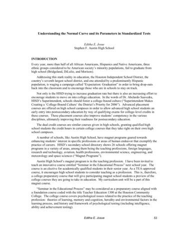
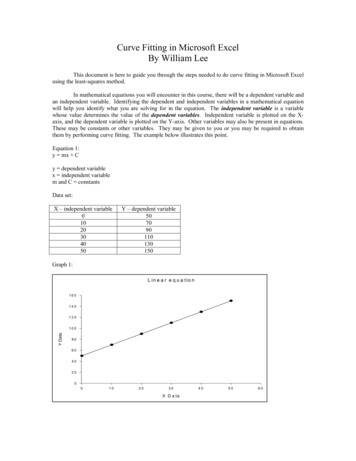
A parabolic curve that is applied to make a smoothand safe transition between two grades on a roadwayor a highway.VPC: Vertical Point of CurvatureVPI: Vertical Point of IntersectionVPT: Vertical Point of TangencyG1, G2: Tangent grades in percentA: Algebraic difference in gradesL: Length of vertical curveVPIVPCVPT
At an intersection of two slopes on a highway ora roadway To provide a safe and comfort ride for vehicleson a roadway.
Two kinds of verticalcurve Crest Vertical Curves Type I and Type II Sag Vertical Curves Type III and Type IV.
Def: the horizontal distance in feet (meters)needed to make 1% change in gradient. Application: To determine the minimum lengths of vertical curves To determine the horizontal distance from the VPC tothe high point of Type I or the low point of Type III
Minimum length of a crest vertical curve needsto satisfy the safety, comfort, and appearancecriteria. Minimum length of a crest vertical curve is equal3 time the design speed (only for English Unit).
General equation for the length of a crest vertical curvein terms of algebraic difference in grades. When S is less than L When S is greater than LL 100(AS 22h1 (2h )22200 h1 h2L 2S A)2L: length of vertical curve, ftS: sight distance, ftA: algebraic difference in grades, percenth1: height of eye above roadway, ft (3.5ft)h2: height of object above roadway surface, ft (2ft) These equations are often used to check the design speedof an existing vertical curve. K values are preferred to beused when design a new vertical curve because itprovides a better safety distance.
Design base on stopping sight distance Design base on passing sigh distanceMUTCD passing sight distance Decision sight distance
Def: the total distances from when the driver decidesto apply the break until the vehicle stop.d 1.47Vt 1.075V2/at: break reaction time, (assumed2.5s)V: design speed, mpha: deceleration rate, ft/s2Page 113 of AASHTO’s A Policy on Geometric Designof Highways and Streets 2004
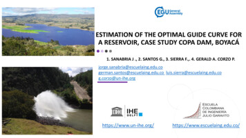
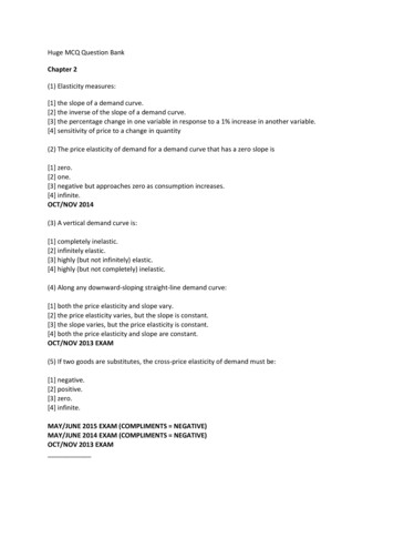
In Exhibit 3-72, K values are calculated by the equation. K values can also be used when S L because there is nosignificant error between S L and S L.S2K 2158Page 272 AASHTO’s A Policy on Geometric Design of Highways and Streets 2004
Page 271 of AASHTO’s A Policy on Geometric Design of Highways and Streets 2004.
An engineer is assigned to design a vertical curve for a highwaywith the design speed is 70 mph. Knowing that the gradients are 3%uphill and -2% downhill. What is the minimum design length of thevertical curve?Solution: Find the value of K from exhibit 3-72. (page 272 of AASHTO2004)For 70mph K 247 Find the value of algebraic difference in gradeA G1 - G2A 3 - (-2)A 5Find minimum length of the vertical curve by using equationL K*AL 247 * 5 1235 ftOr using exhibit 3-71 (page 271 of AASHTO)
Def: the distance that allows a driver to complete a normal pass whilethat driver can observe that there is no potential threat ahead beforemaking the pass. Total of below distances is the design distance for two lanes highway. Initial maneuver distanceDistance while passing vehicle occupies left laneClearance distanceDistance traversed by an opposing vehicleRarely use in crest vertical design because it is difficult to fit thelength of the curve. Can be used when the design speed is low and does not have highgradient, or higher speed with very small algebraic difference ingrades Commonly use at location where combinations of alignment andprofile do not need the use of crest vertical curves Height of an object is assumed to be 3.5ft instead of 2ft in generalequation. (Simplified equation can be found on page 270 of AASHTOGreen Book)
In exhibit 3-7, K values are calculated by the equationPassing vehicle speed usually is assumed 10 to 15 mph higher thanthe passed vehicle.S2K 2800From page 124 of AASHTO’s A Policy on Geometric Design of Highways andStreets 2004
These length are 7 to 10 times longer than the stopping sight distances.Page 272 of AASHTO’s A Policy on Geometric Design of Highways and Streets2004
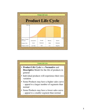
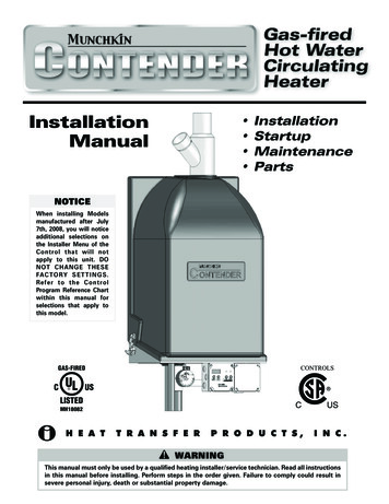
Def: “the distance at which an object 3.5ft above pavement surface can beseen from a point 3.5ft above the pavement.” (page 3B-5) Only use for traffic operation-control needs, such as placing “No Passing”zone warrant. Minimum passing sight distances are shown in Table 3B-1, page 3B-7 of 2003MUTCD book. Page 3B-8 ofMUTCD 2003version
Page 3B-7 of MUTCD 2003 version
Def: “the distance needed for a driver to detect anunexpected or otherwise difficult-to-perceiveinformation sources or condition in a roadwayenvironment that may be visually cluttered,recognize the condition or its potential threat, selectan appropriate speed and path, and initiate andcomplete the maneuver safety and efficiently.” (page115, AASHTO) Exhibit 3-3 provides values for the decision sightdistances that may be appropriate at critical locationsand serve as criteria in evaluation the suitability ofthe available sight distance.
Page 116 of AASHTO’s A Policy on Geometric Design of Highways and Streets, 2004 Avoidance maneuvers A and B are determined as Avoidance maneuvers C, D, and E are determined as d: decision distancet: pre-maneuver time, sV: design speed, mphA: driver acceleration, ft/s2
A design of a sag vertical curves need to satisfy at least four differencecriteria. Head light sight distancePassenger comfortDrainage controlGeneral appearanceGeneral equationS LAS 2L 200(h1 S tan β )S L200(h1 S tan β )L 2S AL: length of sag vertical cure, ftS: light beam distance, ftA: algebraic difference in grades, percent : angle of light beam intersects the surface of the roadway, degree (assumed 1o)h1: head light height, (assumed 2ft)
The design length of a sag vertical curve is based on the headlight sight distance, but the head light sight distance needs to bedesigned almost equal to the stopping sight distance because ofsafety criterion. Therefore, stopping sight distance values can beuse for S value in general equation. Therefore, K values can beused to calculate the length of the curve.For passenger comfort, the below equation can be used. L: length of sag vertical curve, ft A: algebraic difference in grades, percent V: design speed, mph AV 2L 46.5Drainage of curbed roadways needs to retain a grade at least 0.5percent or sometimes 0.3 percent for outer edges of the roadway.For appearance, the minimum curve length can be calculated byequation L 100A for small or intermediate values of A.
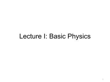
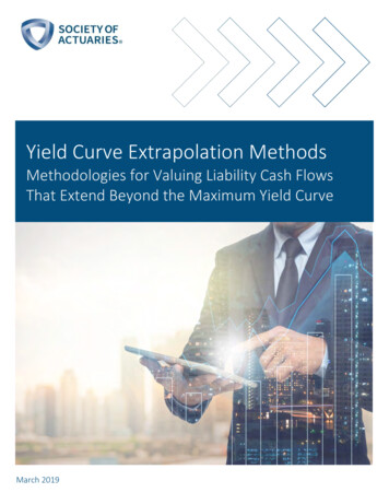
In exhibit 3-75, K values are calculated by equationS2K 400 3.5SPage 277 AASHTO’s A Policy on Geometric Design of Highways and Streets2004
Page 275 of AASHTO’s A Policy on Geometric Design of Highways and Streets2004
Paying more attention to the drainage design when value of K 167The length of vertical curve can be computed by using K values in both crest and sagvertical curves.Minimum length of a crest vertical curve is equal 3 time the design speed (only for EnglishUnit).The “roller-coaster” or the “hidden up” type of profile should be avoided.Two vertical curves in the same direction separated by a short section of tangent gradeshould be avoided.On long grades, the steepest grades should be placed at the bottom of the curve and flattenthe grades near the top of ascent.It is desirable to reduce the grade through the intersection where at-grade intersection occuron roadway sections with moderate to steep grades.Sag vertical curves should be avoided in cuts unless adequate drainage can be provided.The stopping sight distance for trucks is not necessary to be considered in designing verticalbecause the truck driver able to see farther than passenger car. For that reason, the stoppingsight distance for trucks and passenger cars is balance.Most of cases the stopping sight distance will be used for vertical design length, butengineering judgments also get involve in decision making.
American Associationof State Highway andTransportation Officials (AASHTO). (2004).A Policy on Geometric Design of Highwaysand Streets, Fifth Edition. Washington, D.C Manual on Uniform Traffic Control Devices(MUTCD). (2003). Millennium Edition.
An engineer is assigned to design a vertical curve for a highway with the design speed is 70 mph. Knowing that the gradients are 3% uphill and -2% downhill.