Transcription
atAustinPetroleumExtensionTheUniversityofTexasLNG: Basics ofLiquefied Natural GasThe University of Texas at Austin Petroleum extension service
Cascade ProcessUniDescription of Linde MFC LNG ProcessPrecooling and Liquefied Petroleum Gas (LPG) RecoveryLiquefaction and 515152Exs20ReferencesLNG SHIPPING INDUSTRYLNG FleetTypes of LNG ShipsMossMembranePrismaticReducing Greenhouse Gas EmissionsReferencesMAJOR EQUIPMENT IN LNG INDUSTRYCryogenic ExchangersSpiral-Wound Heat 3637Comparing Two Methods of Compositional Adjustment5.017Trend in LNG Train CapacityStrategy for Grassroots PlantReferencesRECEIVING TERMINALReceiving Terminals in the U.S.Main Components and Process DescriptionsMarine FacilitiesStorage CapacityProcess DescriptionsIntegration with Adjacent FacilitiesGas InterchangeabilityNitrogen InjectionExtracting C2 Componentste4.0xaofversDescription of ConocoPhillips Optimized CasadeSM (COPOC)LiquefactionLNG Flash and StorageOther Liquefaction Processes141717ityDescription of Air Products C3MR LNG ProcessLiquefactionLNG Flash and StorageTable FOREWARDACKNOWLEDGEMENTSABOUT THE AUTHORS1.0 INTRODUCTION2.0 OVERVIEW OF LNG INDUSTRYHistory of LNG IndustryBaseload LNGSnapshot of Current LNG IndustryDeveloping an LNG ProjectReferences3.0 BASELOAD LIQUEFACTION PLANTLiquefaction TechnologiesPropane Precooled Mixed Refrigerant Process38 iii
Ambient Air VaporizerssxaTeDirect Heating with SeawaterIndirect Heating with SeawaterofDirect Heating with Ambient AirIndirect Heating with Ambient AirityReferencesSUPPORTING FUNCTIONAL UNITS IN LNG PLANTSGas PretreatmentSlug CatcherNGL Stabilizer ColumnAcid Gas Removal UnitMolecular Sieve DehydratorMercury and Sulfur Removal UnitNGL RecoveryIntegrating NGL and LNG PlantsNitrogen RejectionHelium RecoveryReferences8.0SAFETY, SECURITY, AND ENVIRONMENTAL ISSUESSafety Design of LNG FacilitiesSecurity Issues for the LNG IndustryEnvironmental IssuesReferences9.0OFFSHORE APPLICATIONSOffshore Design ConsiderationsOffshore Receiving TerminalOffshore LNG ProductionOffshore LNG TransferReferences10.0SPECIAL TOPICSNonconventional LNGRisk-Based Analysis for an LNG ProjectReferencesAPPENDICESAppendix A. Conversions FactorsAppendix B. Properties of LNGAppendix C. in Heat ExchangersCold BoxesCompressors and DriversCentrifugal CompressorsAxial CompressorsReciprocating CompressorsGas TurbinesLNG Pumps and ExpandersLNG PumpsLiquid ExpandersLoading ArmsLNG TanksLNG VaporizersSubmerged Combustion VaporizersOpen Rack VaporizersShell and Tube 9125137LNG: Basics of Liquefied Natural Gas
atAustinAbout theAuthorsxaTePetroleumExtensionTheUniversityofDr. Stanley Huang has a specialtyarea in cryogenic applications, particularly in LNG and gas processing. He hasworked on many projects of LNG baseloadplants and receiving terminals since 1996.Dr. Huang has contributed to the processand technology improvements through more than 20 publications andcorporate reports. He worked for IPSI (an affiliate of Bechtel) and KBR,before joining Chevron. Currently he is a Staff LNG Process Engineer.By training Dr. Huang is an expert in thermodynamics, in whichhe still maintains keen interest. He graduated from National TaiwanUniversity with a B.S. degree and attended Purdue University in 1981.He earned his Master and Ph.D. degrees there, all in Chemical Engineering. Additionally, he also acquired a Master of Science in physics. Afterleaving school he worked for Exxon Research and Engineering Companyas a post-doctoral Research Associate. Then he joined DB Robinson andAssociates in Alberta, Canada for six years. Dr. Huang contributed morethan 30 papers and corporate reports before 1996, including a molecularlybased equation of state, called Statistical Associated Fluid Theory (SAFT),which is still popular in polymer applications today.Dr. Huang is a Registered Professional Engineer in Texas. Hegave seminars on thermodynamic applications at Chinese PetroleumCorporation, National Chung-Yan University, and National Institute ofIndustrial Technology in Taiwan. In recent years he also gave seminarson gas processing and LNG industry at Association of Chinese AmericanProfessionals (ACAP) meetings, Universities of Houston and Wyoming.s xi
atAustin PetroleumExtensionTheUniversityofTexasDr. Chen-Hwa Chiu has worked onmany baseload LNG and LNG receiving terminal projects, and participatedin the startup of Arun LNG plant. He hascontributed to technological development,energy integration, safety, and cost reduction in large-scale baseload LNG plants and LNG terminals. A Fellow ofAmerican Institute of Chemical Engineers, he served as the Chair of itsFuels and Petrochemicals Division. He has won the George Lappin National Program Committee Service Award, AIChE, 2006, and the Distinguish Service Award, Fuels and Petrochemicals Division of AIChE in 2004.Dr. Chiu was an author of a Chapter in a Wiley Encyclopedia onEnvironmental Remediation and Analysis. He has over 80 publications,encyclopedia chapters, proceedings, and 2 patents. A frequent speaker onmajor international conferences on LNG, he is the chief organizer of theLNG sessions for the Topical Conference on Natural Gas Utilization andeditor of its 7 proceedings from 2001 to 2007 for AIChE.He has established and conducted the popular “Fundamentalsof LNG Technology” for the Chevron professionals since 2000. He haslectured at Chinese Petroleum Corporation, National Taiwan University,National Cheng Kung University, and recently at the Lamar Universityon LNG Industry. Dr. Chiu graduated from National Taiwan Universitywith a B.S. and earned his Master of Engineering and Ph.D. from theUniversity of Oklahoma, all in Chemical Engineering. He is a RegisteredProfessional Engineer in Texas and Pennsylvania. He has worked forLummus, Air Products, Exxon, M.W. Kellogg, Bechtel, Fluor, and Texaco,before Chevron. Dr. Chiu is a senior technology advisor of Chevron EnergyTechnology Company.xiiLNG: Basics of Liquefied Natural Gas
atAustinxaTePetroleumExtensionTheUniversityofDr. Doug Elliot has over 40 yearsexperience in the oil and gas business, devoted to the design, technologydevelopment, and direction of industrialresearch. Doug is currently President,COO and cofounder (with Bechtel Corporation) of IPSI LLC, a company formed in 1986 to develop technologyand provide conceptual design services to oil and gas producing andEPC companies. Prior to IPSI, Doug was Vice President of Oil and Gaswith Davy McKee International. Doug started his career with McDermottHudson Engineering in the early 1970s following a post-doctoral researchassignment under Professor Riki Kobayashi at Rice University, where hedeveloped an interest in oil and gas thermophysical properties researchand its application. Doug has authored or coauthored over 65 technicalpublications plus 12 patents.Doug served as a member of the Gas Processors Association (GPA)Research Steering Committee from 1972 to 2001 and as Chairman of theGPSA Data Book Committee on Physical Properties. Doug served as Chairman of the South Texas Section and Director of the Fuels and PetrochemicalDivision of the AIChE; and is currently a member of the PETEX AdvisoryBoard. He holds a B.S. degree from Oregon State University and M.S. andPh.D. degrees from the University of Houston, all in chemical engineering. Doug is a Bechtel Fellow and a Fellow of the American Institute ofChemical Engineers.s About the Authorsxiii
rsityofThe liquefied natural gas (LNG) industry in the U.S. can be traced backto the 1940s. However, the industry never received much attentionfrom the general public until the beginning of this century. Firstly, mostLNG produced in the U.S. is used for peak shaving purposes. Even for thisfunction, LNG cannot distinguish itself from other mechanisms for naturalgas storage, such as salt caverns. Secondly, domestic gas production, withthe help of pipeline imports from Canada, has been mostly self-sufficientuntil the end of the past century, so there was no need to import LNG inany significant quantity. Using LNG as a baseload fuel had a false start in the1970s. Of the four LNG import terminals built at the time, only two (Everettin Massachusetts and Lake Charles in Louisiana) managed to stay in operation during that time.With the increased consumption and dwindling domestic natural gasproduction in recent years, LNG imports are projected to increase significantlyin the near future. There have been close to 50 proposals for constructing newLNG receiving terminals on both coasts and the Gulf of Mexico areas. The publicinterest in LNG is also aroused by the unprecedented high natural gas prices.In response to the heightened interest, this book provides a comprehensive coverage of all domains in the LNG industry. One intended use ofthis book is for the training classes presented by the Petroleum ExtensionService (PETEX) of The University of Texas. The readers of this book areassumed to be managers new to the LNG industry or operating personnelwho have already accumulated suitable technical background. The focus ofthe materials will be on the process side so as to present an overall pictureregarding how LNG liquefaction and regasification facilities work and why theindustry has evolved. Of course, no descriptions can be complete withouttouching the key equipment, particularly those items specific to the industry.The way we acquire information has changed dramatically in theinformation age. The pace of change accelerated in the past ten years afterhigh-speed internet connections and powerful search engines became generally available. It is almost a daily experience that we provide only the “keywords” and gain access to myriads of information coming from the internet.The presentation style of this book reflects this reality. Instead of detaileddescriptions of a chosen topic, we provide brief but comprehensive coverageof the ideas involved. Interested readers can pick up the correct key wordsto easily gain access to more detailed information from the internet. Moreimportantly, comprehensive coverage will enable the reader to judge therelevance of searched information and not get lost in a sea of information.Out of the hundreds, probably thousands, of Web sites related to theLNG industry, the site run by the Oil and Gas Journal (OGJ) has been heavilyreferenced. Throughout the years, OGJ has become an industrially recognizedleader in providing information in the hydrocarbon industry. Additionally,the database, which is maintained by OGJ after 1990, is user-friendly andcomprehensive.Te 1
atAustin2xasOverview ofLNG IndustrynsionTheUniversityofThis chapter provides an overview of the LNG industry, from the development of cryogenic technology to the modern-day gas monetizationmega-projects. A historical perspective is helpful in appreciating the currentstatus of the industry.There are four distinctive phases in the life cycle of an industry: development, expansion, saturation, then decline or transformation. Two wellknown examples are the coke and steel industries (Anderson and DeLawyer,1995). In the very beginning, as the developing technology is seeking publicacceptance, the industrial scale is small and expansion is usually slow. Oncethese hurdles in technology development and acceptance are overcome, afast expansion phase follows. The saturation phase sets in when the widelypracticed technology is challenged by other emerging ones or parallel competitions reduce the profit margin to a merely sustainable level. At this point,the industry either can decline or transform and rejuvenate the life cycle.It is difficult to pinpoint the exact phase of LNG industry at the presentmoment. However, there are indications that it has passed its developmentstage and is entering the expansion phase. This is witnessed by the surge ofannounced LNG projects in the past few years. However, how long this trendwill last and to what extent it will continue probably only future historianswill be able to tell (True, 2006).The first section of this chapter provides a brief history of the LNGindustry, describing the technological advances that contributed to its wideacceptance nowadays. The second section describes the emergence of the baseload LNG industry and the essential components. The third section providesa snapshot of the current LNG industry and its role in global gas trading. Thelast section provides a brief description of steps in forming an LNG project.Te HISTORY OF LNG INDUSTRYPetroleumExteAlthough the cryogenic disciplines for gas liquefaction were developed inthe late 19th Century, the early commercial efforts were directed toward airliquefaction and separation. Many companies formed at that time, such asBritish Oxygen Company (BOC), Air Liquide, and Linde, remain familiartrade names today (Scurlock, 1992).The advantages of using liquefaction to reduce gas volumes and vaporpressures for fluid storage and transportation were noticed by the naturalgas industry. The first pilot plant for natural gas liquefaction was built inWest Virginia in 1939. The results were so encouraging that in 1941 the firstcommercial LNG plant was completed in Cleveland, Ohio. In the next fewyears, several relatively large spherical storage vessels were added. In 1944,a large cylindrical LNG tank with a novel base-construction design failed,because insufficient metallurgical knowledge at the time allowed the tankto be built with 3.5 percent nickel steel. The leaked LNG discharged into thesewage system of a neighboring, congested community and resulted in acatastrophic explosion, which demolished the entire community and caused128 deaths. This incident halted LNG development for a decade.The development of the LNG industry resumed after it was concludedthat 9 percent nickel steel was adequate for LNG storage applications. Thisspecification is still in use today.3
rsityofThe liquefaction plant is the most capital-intensive link in the entireLNG monetary chain. This chapter provides some detailed descriptionsof the cryogenic liquefaction unit, the technical core of this link. There areother supporting units in an LNG plant, such as gas sweetening, dehydration,NGL removal, and nitrogen (N2) rejection. They will be covered in Chapter 7.The basis of the following discussion is a single LNG train. Combiningseveral LNG trains to form an LNG plant or complex for utility-sharing willnot be addressed. These issues are more related to the plant layout, reliability,and economics. Also, only the onshore applications will be covered in thischapter. Offshore applications are mainly extensions of onshore counterpartsand will be covered in Chapter 9.The first section of this chapter describes three LNG processes to familiarize readers with the technical domain. The second section describestrain-capacity trends resulting from technological advances. The last sectiondescribes challenges faced by the industry during the construction of a baseload LNG plant. Experiences are provided for references in future projects.It should be emphasized that each project has its own characteristic featuresand difficulties. Past experiences may serve as useful guidelines to avoidthe same traps. However, discretion should be used as to the applicabilityof these experiences on specific projects.The development of an LNG liquefaction process is an on-going endeavor. Not only are novel processes being patented, improvements andvariations of existing ones are constantly being proposed, studied, and installed. Cumulatively, all these innovations and incremental improvementscontribute to the success of the LNG industry today. The LNG plants todayare efficient, safe, and cost-effective. In particular, their safety records areexemplary in the energy sector.Te LIQUEFACTION TECHNOLOGIESPetroleumExteThere are more than 100 patents in the U.S. alone describing different processes for LNG liquefaction. However, only a handful of processes have beeninstalled commercially. Among those installed, some encountered operationaland reliability challenges. Afterwards, they were never used again. Othersemerged only recently and are still in the process of construction.Process selection significantly affects the outcome of an LNG project.Extensive discussions are available in the open domain to address issuesrelated to process efficiency, plant constructability and operability, economicperformances, and environmental concerns (Chiu, Dimitroff, and Shah, 2006;Mokhatab and Economides, 2006; Yost and DiNapoli, 2003).Three examples are presented below to highlight the main features ofLNG processes. The criteria for choosing the three examples include theircommercial success or perceived commercial potential. The three processesare: propane precooled mixed refrigerant (C3MR) liquefaction process of theAir Products company, ConocoPhillips Optimized CascadeSM Process (COPOC),and multi-fluid cascade process (MFC ) of Linde.13
UniversityofThe receiving terminal is an indispensable link between LNG ships andthe targeted pipeline grid. The terminal serves three functions: (1) toreceive and store ship-delivered LNG, (2) to regasify the LNG, with optionalcompositional adjustments, and (3) to deliver contracted volumes of gas intothe designated pipeline grid at specified times. Thus, the storage capacityin a receiving terminal also provides adequate buffering should inclementmarine conditions interrupt the LNG delivery for a finite number of days.The global operational capacity of LNG receiving terminals shouldmatch that of the production, as shown in Table 2.1. Japan is the largest LNGimporting country which accounts for about 40 percent of global LNG trade.In contrast, the U.S. currently imports less than 10 percent of global LNGsupplies. The scenario is projected to change by the year 2025, when the U.S.is expected to import about 30 percent of the globally-traded LNG, matchingthe level of Japan at that time. Also, the imported LNG will account for 20percent of the U.S. domestic gas balance (Shanley et al., 2004; Martin, 2005).The global-installed capacity of LNG receiving terminals exceeds thatof production. This excess receiving capacity is used by some countries asan assurance against possible interruptions in the LNG delivery links. Forexample, there is no national gas pipeline grid in Japan and each powercompany is expected to provide its own LNG spare capacity. As a result,there is excess LNG capacity in Japan if viewed from a national perspective.Another example of excess receiving capacity is in the U.S., where two offour terminals were moth-balled due to unfavorable operating economicsin the past 30 years.Since the U.S. market is the major driving force behind the currentglobal LNG boom, this chapter will focus on the U.S. LNG market. Thechapter is divided into four sections. The first section describes receivingterminals in the U.S. The second section provides technical descriptions ofa typical receiving terminal. The third section discusses the possibility ofintegrating the refrigeration in a receiving terminal with other facilities inits vicinity in order to improve the overall thermodynamic efficiency of thewhole system. The fourth section describes the issue of gas interchangeability,which assures that imported LNG, after being regasified and delivered intothe existing pipeline grid, is compatible with existing domestically-producedgas. This assurance eliminates possible adverse impacts on end users due tocompositional changes.Te 27
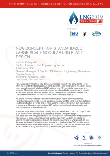
atAustin5xasLNG ShippingIndustryityofShipping is a key link in the LNG monetization chain. In currentLNG commercial practices, where there are minimum activities inspot markets, few LNG ships are built on noncommitted bases. Each LNGproject includes its own dedicated LNG fleet. The occasional transportationneeds created by spot market activities are met by chartering ships withspare load capacity available at the desired times and locations. LNG spotmarket transactions are expected to increase in the future, as will the volumeof LNG transported by nondedicated ships chartered after construction onvariable terms.This chapter is divided into three sections, the first of which provides aglobal view of the current global LNG ship fleet. As anticipated, the upsurgeof LNG capacity in the next few years will be matched by expansion of theLNG fleet. The second section is further divided into three subsections todescribe three types of LNG ships: Moss, membrane, and prismatic. The thirdsection describes the measures the LNG shipping industry taken to reducegreenhouse gas emissions.Te versLNG FLEETPetroleumExtensionTheUniSimilar to efforts to expand the production capacity of LNG productiontrains, LNG ship-builders have been striving to increase ship size to capturethe economy of scale. However, the advances in ship-building technologyappear as quantum leaps compared to the gradual expansion of the LNG traincapacities. The maximum size of LNG ships recently increased to 210,000 m3after languishing at about 140,000 m3 since 1975 (Cho et al., 2005). As a resultof this long plateau, the capacities of most current LNG ships fall between100,000 m3 and 140,000 m3. Figure 5.1 shows the global ship-size distributionas of 2005 (Rajvanshy, 2005).Figure 5.1Sizes of global LNG ships in 200541
atAustin6xasMajorEquipment inLNG IndustryityofThere are hundreds of equipment items in an LNG plant. It would bedifficult to describe everything in a single book. Fortunately, manyof the same equipment items are also used in the gas processing industry.Excellent general references on the Web or in print are available for theseitems (GPSA, 2000; Perry and Green, 1997). Examples include vessels, towers, air coolers, shell and tube exchangers, centrifugal and piston pumps,compressors and drivers and, optionally, gas expanders.This chapter focuses on selected items specific to the LNG industry.These items include cryogenic exchangers, large compressors and drivers, LNGpumps and liquid expanders, loading arms, LNG tanks, and LNG vaporizersused in receiving terminals. Large compressors and drivers are includedbecause their size makes their applications unique.Each item of LNG equipment is explained in the following seven sections. The photos used to illustrate this equipment have been reprinted withpermission from kind many LNG vendors currently supplying the LNGindustry.Te versCRYOGENIC EXCHANGERSPetroleumExtensionTheUniAluminum, because of its superior thermal conductivity and mechanicalstrength at low temperatures, is a favored material for cryogenic applications.For clean and noncorrosive (NC) fluids, aluminum-based construction shouldbe considered, if the temperature is below 35 C. The large-scale applicationof aluminum-based cryogenic exchangers is an important factor contributingto the success of modern gas processing and LNG plants.There are two common methods in constructing the aluminum-basedcryogenic exchangers: spiral-wound heat exchangers (SWHEs) and plate-fin heatexchangers (PFHEs). Sometimes PFHEs are also called brazed-aluminum heatexchangers (BAHEs). Spiral-wound designs can be traced to the early development of cryogenic processes for air liquefaction by Dr. Carl von Linde inMay 1885. In the early days, three important manufacturers were Linde andHampson in Europe, and Tripler in the U.S. The brazed-aluminum methodwas developed relatively late, after World War II. This method revolutionizedthe cryogenic exchanger design because it made possible the complex multipass arrangements and narrow temperature approaches (Scurlock, 1992).In today’s competitive commercial environment, several players in eachmanufacturing method are competing for the market. The first two subsections below will discuss the two methods separately. The third subsectionwill describe an insulation technique called “cold box,” which can houseseveral pieces of cryogenic equipment items. This method of insulation iscommon in cryogenic plants.51
atAustin7xasSupportingFunctionalUnits in LNGPlantsnsionThGAS PRETREATMENTeUniversityofThere are many functional units inside an LNG plant besides the corecryogenic and liquefaction units covered in Chapter 3. Figure 7.1 presents a schematic showing the relations between different functional units.Those units covered in Chapter 3 are highlighted in the figure. This chapterwill cover the other supporting functions, including gas pretreatment, naturalgas liquid (NGL) recovery, nitrogen rejection, and helium recovery.There are four sections in this chapter. The first section covers the gaspretreatment unit, which includes gas receiving, NGL stabilizing, gas sweetening, gas precooling, and gas dehydrating. Inlet gas must be sweetened anddried before it can be directed to the cryogenic unit. The second section covers the NGL recovery operation, the purpose of which is to meet a specifiedLNG heating value as well as compositional specifications. The third sectiondiscusses the nitrogen rejection unit (NRU), the purpose of which is to meetnitrogen composition specifications. Finally, the fourth section discusses helium recovery. In some LNG plants, where inlet gases contain relatively highproportions of helium, helium recovery can enhance the economic attractiveness of an LNG project.These operations are not unique to the LNG industry and also are standard operations in gas processing industries. There are many good technicalreferences (GPSA, 2000; Kohl and Nielsen, 1997; Dinh et al., 2005) to help explainmore about these operations in publications and on the Web. This chapter willonly provide brief functional descriptions for these supporting units to givereaders a complete picture of typical LNG plants.Te This section describes the following units: gas reception, NGL stabilization,acid gas removal, molecular sieve dehydration, and sulfur and mercuryremoval. The first two units sometimes are referred to as upstream facilities.Slug CatcherPetroleumExteA slug catcher is a buffering apparatus at the end of a pipeline, which includesa storage vessel sized to hold periodic in-flows of large volumes of liquidscreated by pigging or liquid surges. The slug catcher also acts as a means ofensuring steady outlet flows to downstream liquid handling facilities. Figure7.2 shows a photo of the slug-catching facilities (foreground) of the StatoilSnøhvit LNG plant in Melkøya Island, Norway.The initial separation of gas, liquids, and chemicals takes place in theslug catcher. Sometimes chemicals are injected into upstream pipelines tocontrol corrosion or to prevent formation of hydrates or solids. Gas continues todownstream pretreatment facilities while hydrocarbon liquids are processedin the NGL stabilization plant. Chemicals, such as hydrator inhibitor, needto be reclaimed in specially designed regeneration facilities.Structurally, a slug catcher may be a single large vessel or a collection ofmanifolded pipelines. The finger-type slug catching facilities shown in Figure 7.2are visible in the foreground. When this LNG facility was under construction,the slug catcher was fabricated in a construction yard elsewhere and barged87
atAustin8xasSafety,Security, andEnvironmentalIssueseSafety Design of LNG FacilitiesUniversityofThe U.S. has a long history of working with LNG starting withpeak shaving applications. Today there are more than 100 LNGfacilities scattered around the country, as shown in Figure 2.1, page4. Baseload LNG applications have not proliferated since being introduced in the U.S. in the early 1970s. Rapid growth of U.S. LNG-importcapacity began in the early 2000s because of dwindling domestic gasproduction.Overall, the LNG industry has demonstrated an excellent safety record(Foss, 2003). In addition, dedicated journals address safety issues and concerns periodically to propagate awareness among industrial players (Westand Chiu, 2005).LNG safety, security, and environmental imperatives changed profoundly after the terrorist attack on the World Trade Towers in New YorkCity on September 11, 2001. An LNG ship or storage tank contains a tremendous amount of energy. Upon sudden breach of the containment system,the released LNG poses a real safety concern. How to mitigate the potentialhazard is still actively debated.As a source of energy, LNG will play an evermore important role inU.S. domestic gas markets. With current public focus on mitigating CO2emissions and energy efficiency, the LNG industry is proactively responding to these concerns.This chapter is divided into three sections: industrial safety, security,and environmental issues.Te nsionThIn the safety domain, LNG has the following advantages over other industries:1. The physical and chemical properties of LNG are well understood.LNG exists only under cryogenic conditions. In order to manufacture LNG on a large scale, these properties are required to supportindustrial designs.umExte2. The industry has evolved around a tradition of safe designs andoperations which includes rigorous personnel training. To createand preserve cryogenic conditions economically, it is of utmost importance to minimize unscheduled process interruptions. Short-cutslead to increased plant downtime contrary to economic principles.Hence, the LNG industry intrinsically self-regulates toward safedesigns and operations.Petrole3. Codes and regulations have been evolving synchronously with theLNG industry rather than being developed only after major industrial accidents.99
verstensionTheUnibarg, 30base
tional Program Committee Service Award, AIChE, 2006, and the Distin-guish Service Award, Fuels and Petrochemicals Division of AIChE in 2004. Dr. Chiu was an author of a Chapter in a Wiley Encyclopedia on Environmental Remediation and Analysis. He has over 80 publications, encyclopedia chapters, proceedings, and 2 patents. A frequent speaker on


![Public Input No. 12-NFPA 497-2014 [ Chapter 2 ]](/img/62/497-a2016-eec-aaa-fd-piresponses.jpg)