Transcription
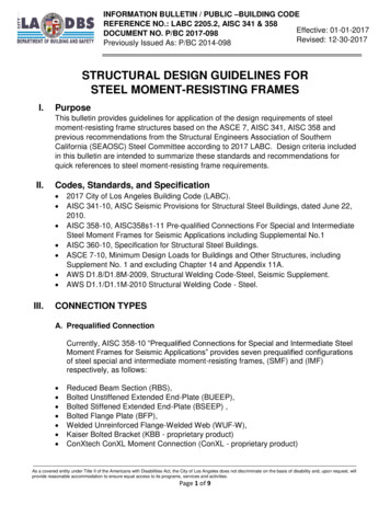
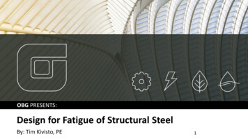
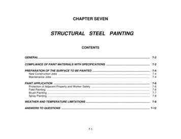
Design of Structural Steel Pipe RacksRICHARD M. DRAKE and ROBERT J. WALTERABSTRACTPipe racks are structures in petrochemical, chemical and power plants that are designed to support pipes, power cables and instrument cabletrays. They may also be used to support mechanical equipment, vessels and valve access platforms. Pipe racks are non-building structures thathave similarities to structural steel buildings. The design requirements found in the building codes are not clear on how they are to be applied topipe racks. Several industry references exist to help the designer apply the intent of the code and follow expected engineering practices. Thispaper summarizes the building code and industry practice design criteria, design loads and other design consideration for pipe racks.Keywords: non-building structures, pipe, racks, support, designPipe racks are structures in petrochemical, chemical andpower plants that support pipes, power cables and instrument cable trays. Occasionally, pipe racks may also supportmechanical equipment, vessels and valve access platforms.Pipe racks are also referred to as pipe supports or pipeways.Main pipe racks transfer material between equipment andstorage or utility areas. Storage racks found in warehousestores are not pipe racks, even if they store lengths of piping.To allow maintenance access under the pipe rack, transverse frames (bents) are typically moment-resisting framesthat support gravity loads and resist lateral loads transverseto the pipe rack. See Figure 1 for a typical pipe bent. Although the bent is shown with fixed base columns, it can alsobe constructed with pinned base columns if the supportedpiping can tolerate the lateral displacement.The transverse frames are typically connected with longitudinal struts. If diagonal bracing is added in the verticalplane, then the struts and bracing act together as concentrically braced frames to resist lateral loads longitudinal to thepipe rack. See Figure 2 for an isometric view of a typicalpipe rack.If the transverse frames are not connected with longitudinal struts, the pipe rack is considered to be “unstrutted.”The frame columns act as cantilevers to resist lateral loadslongitudinal to the pipe rack.Fig 1. Typical transverse frame (bent).Richard M. Drake, S.E., SECB, Senior Fellow, Structural Engineering, FluorEnterprises, Inc., Aliso Viejo, CA (corresponding author). E-mail: rick.drake@fluor.comRobert J. Walter, S.E., P.E., Principal Civil/Structural Engineer, CB&I SteelPlate Structures, Plainfield, IL. E-mail: rwalter@cbi.comFig. 2. Typical four-level pipe rack consisting of eighttransverse frames connected by longitudinal struts.ENGINEERING JOURNAL / FOURTH QUARTER / 2010 / 241241-252 EJ4Q 2010 2009 26.indd 2412/21/11 4:53 PM
DESIGN CRITERIAIn most of the United States, the governing building codeis the International Building Code (IBC) (ICC, 2009). Thescope of this code applies to buildings and other structureswithin the governing jurisdiction. The IBC prescribes structural design criteria in Chapters 16 through 23. These design criteria adopt by reference many industry standardsand specifications that have been created in accordance withrigorous American National Standards Institute (ANSI)procedures.By reference, many loads are prescribed in ASCE 7(ASCE, 2006). Similarly, most structural steel material references are prescribed in AISC 360 (AISC, 2005b). Moststructural steel seismic requirements are prescribed in AISC341 (AISC, 2005a) and AISC 358 (AISC, 2006, 2009).The IBC and its referenced industry standards and specifications primarily address buildings and other structures to alesser extent. Design criteria for non-building structures areusually provided by industry guidelines. These guidelinesinterpret and supplement the building code and its referenced documents. In the case of pipe racks, additional design criteria are provided by Process Industry Practices, PIPSTC01015 (PIP, 2007) and ASCE guidelines for petrochemical facilities (ASCE, 1997a, 1997b). In this article, the IBCrequirements govern. The aforementioned industry standards and specifications apply because they are referencedby the IBC. The PIP practices and ASCE guidelines may beused for pipe racks because they supplement the IBC andthe referenced industry standards and specifications. However, the PIP practices and ASCE guidelines are not codereferenced documents.DESIGN LOADSDead Loads (D)Dead loads are defined in the IBC as “the weight of materials of construction including, but not limited to structural items, and the weight of fixed service equipment, suchas cranes, plumbing stacks and risers, electrical feeders ”Dead loads are prescribed in the IBC Section 1606, with noreference to ASCE 7 or any industry standard or specification.The PIP Structural Design Criteria prescribes specificdead loads for pipe racks. Pipe racks and their foundationsshould be designed to support these loads applied on allavailable rack space, unless other criteria is provided by theclient. Structure dead load (Ds): The weight of materialsforming the structure and all permanently attachedappurtenances. This includes the weight of fire protection material, but does not include the weight ofpiping, cable trays, process equipment and vessels. Operating dead load (Do): The operating dead load isthe weight of piping, piping insulation, cable tray, process equipment and vessels plus their contents (fluidload). The piping and cable tray loads may be based onactual loads or approximated by using uniform loads.The PIP Structural Design Criteria recommends auniformly distributed load of 40 psf for pipe, whichis equivalent to 8-in.-diameter schedule 40 pipes filledwith water at 15-in. spacing. Other uniform loads maybe used based on client requirements and engineeringjudgment. For cable tray levels, a uniform distributedload of 20 psf for a single level of cable trays and 40psf for a double level of cable trays may be used unlessactual loading is greater. Empty dead load (De): The empty weight of piping,piping insulation, cable tray, process equipment andvessels. When using approximate uniform loads, 60%of the operating dead load for piping levels is typicallyused. Engineering judgment should be used for cabletray levels. Test dead load (Dt): The empty weight of the pipesplus the weight of the test medium.The use of large approximate uniform loads may be conservative for the sizing of members and connections. However,conservatively large uniform loads can become unconservative for uplift, overturning and period determination.Live Loads (L)Live loads are defined in the IBC as “Those loads producedby the use and occupancy of the structure, and do notinclude construction or environmental loads such as windload, snow load, rain load, earthquake load, flood load, ordead load.” Live loads are prescribed in IBC Section 1607,with no reference to ASCE 7 or any industry standard orspecification.The minimum live loads applied to platforms and stairsthat are part of the pipe rack structure shall meet the minimum loads per IBC Table 1607.1: Stairs: Per item 35, “stairs and exits—all others” shallbe designed for a 100-psf uniform load or a 300-lbpoint load over an area of 4 in.2, whichever producesthe greater load effects. Platforms: Per item 39, “Walkways and elevated platforms” shall be designed for 60-psf uniform load.The PIP Structural Design Criteria also prescribes specificlive loads which may be applicable to platforms and stairsthat are part of the pipe racks. These loads are higher thanrequired by the IBC Building Code: Stairs: Design for separate 100-psf uniform load and1,000-lb concentrated load.242 / ENGINEERING JOURNAL / FOURTH QUARTER / 2010241-252 EJ4Q 2010 2009 26.indd 2422/21/11 4:53 PM
Platforms: Design for separate 75-psf uniform loadand 1,000-lb concentrated load assumed to be uniformly distributed over an area 22 ft by 22 ft.1Either of the preceding design criteria is acceptable and maybe reduced by the reduction in live loads provisions of IBC.Often, the live load design criteria are specified by the client and may be larger to accommodate additional loads formaintenance. Evaluate drift limits in accordance with ASCE 7,Chapter 12. Consider pipe racks to be non-building structures inaccordance with ASCE 7, Chapter 15. Consider the recommendations of Guidelines for Seismic Evaluation and Design of Petrochemical Facilities(ASCE, 1997a). Use occupancy category III and an importance factor (I ) of 1.25, unless specified otherwise by clientcriteria. Consider an operating earthquake load (Eo). This is theload considering the operating dead load (Do) as partof the seismic effective weight. Consider an empty earthquake load (Ee). This is theload considering the empty dead load (De) as part ofthe seismic effective weight.Thermal Loads (T )Thermal loads are defined in the IBC as “Self-straining forces arising from contraction or expansion resulting from temperature change.” Thermal loads may be caused by changesin ambient temperature or may be caused by the design (operating) temperature of the pipe.The PIP Structural Design Criteria prescribes specificthermal loads for pipe racks: Thermal forces (T ): The self-straining thermal forcescaused by the restrained expansion of the pipe rackstructural members. Pipe anchor and guide forces (Af): Pipe anchors andguides restrain the pipe from moving in one or moredirections and cause expansion movement to occur atdesired locations in a piping system. Anchor and guideloads are determined from a stress analysis of an individual pipe. Beams, struts, columns, braced anchorframes and foundations must be designed to resist actual pipe anchor and guide loads. Pipe friction forces (Ff): These are friction forces onthe pipe rack structural members caused by the slidingof pipes in response to thermal expansion due to thedesign (operating) temperature of the pipe. For friction loads on individual structural members, use thelarger of 10% of the total piping weight or 40% of theweight of the largest pipe undergoing thermal movement: 10% of the total piping weight assumes that thethermal movements on the individual pipes do not occur simultaneously; 40% of the largest pipe weight assumes steel-on-steel friction.The ASCE Guidelines for Seismic Evaluation and Designof Petrochemical Facilities is based on the 1994 UniformBuilding Code (UBC) (ICBO, 1994), and references to various seismic load parameters are based on obsolete allowablestress design equations not used in the IBC. Nevertheless,this document is a useful resource for consideration of earthquake effects.Wind Loads (W)Wind loads are prescribed in IBC Section 1609. This sectionreferences ASCE 7 as an acceptable alternative to the IBCrequirements. Most design practitioners use the ASCE 7wind load requirements.The PIP Structural Design Criteria prescribes that windloads for pipe racks are determined in accordance withASCE 7 and the following: Wind drift with the full wind load should not exceedthe pipe rack height divided by 100. Consider partial wind load (Wp). This is the wind loaddetermined in accordance with ASCE 7 based on awind speed of 68 mph. This wind load should be usedin load combination with structure dead loads (Ds) andtest dead loads (Dt).Earthquake Loads (E)Earthquake loads are prescribed in IBC Section 1613. Thissection references ASCE 7 for the determination of earthquake loads and motions. Seismic detailing of materials prescribed in ASCE 7 Chapter 14 is specifically excluded fromthis reference. Seismic detailing of structural steel materialsare prescribed in IBC Chapter 22.The PIP Structural Design Criteria prescribes that earthquake loads for pipe racks are determined in accordancewith ASCE 7 and the following:The ASCE Wind Guideline (ASCE, 1997b) recommendsthat wind loads for pipe racks are determined in accordancewith ASCE 7 and the following: Calculate wind on the pipe rack structure, neglectingany shielding. Use a force coefficient of Cf 1.8 onstructural members, or alternatively use Cf 2.0 below the first level and Cf 1.6 above the first level. Calculate transverse wind on each pipe level. The tributary height for each pipe level should be taken as theENGINEERING JOURNAL / FOURTH QUARTER / 2010 / 243241-252 EJ4Q 2010 2009 26.indd 2432/21/11 4:53 PM
pipe diameter (including insulation) plus 10% of thepipe rack transverse width. The tributary area is thetributary height times the tributary length of the pipes.Use a minimum force coefficient of Cf 0.7 on pipes. below consider only the load types typically applicable topipe racks (D, L, T, W and E ). Loads usually not applicableto pipe racks are roof live (Lr), snow (S ), rain (R ), ice (Di)and lateral earth pressure (H ).Calculate transverse wind on each cable tray level. Thetributary height for each pipe level should be taken asthe largest tray height plus 10% of the pipe rack transverse width. The tributary area is the tributary heighttimes the tributary length of the cable tray. Use a minimum force coefficient of Cf 2.0 on cable trays.1.4(D F )[IBC Eq. 16-1]1.2(D T ) 1.6L[IBC Eq. 16-2]1.2D (0.5L or 0.8W )[IBC Eq. 16-3]1.2D 1.6W 0.5L[IBC Eq. 16-4]1.2D 1.0E 0.5L[IBC Eq. 16-5]Rain Loads (R)0.9D 1.6W[IBC Eq. 16-6]Rain loads are prescribed in IBC Section 1611. The IBC requirements are intended for roofs that can accumulate rainwater. Pipe rack structural members, piping and cable traysdo not accumulate rain water. Unless the pipe rack supportsequipment that can accumulate rain water, rain loads neednot be considered.0.9D 1.0E[IBC Eq. 16-7]Snow Loads (S)Snow loads are prescribed in IBC Section 1608. This sectionreferences ASCE 7 for the determination of snow loads. TheIBC provisions are intended for determining snow loads onroofs. Typically, pipe racks are much different than buildingroofs, and the flat areas of a pipe rack where snow can accumulate vary. Thus, engineering judgment must be used whenapplying s
Keywords: non-building structures, pipe, racks, support, design Pipe racks are structures in petrochemical, chemical and power plants that support pipes, power cables and instru- ment cable trays. Occasionally, pipe racks may also support mechanical equipment, vessels and valve access platforms. Pipe racks are also referred to as pipe supports or pipeways. Main pipe racks transfer material .