Transcription
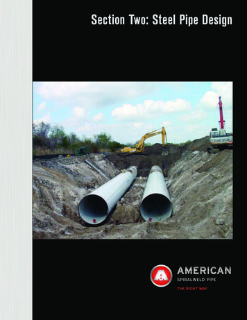
Section Two: Steel Pipe DesignSPIRALWELD PIPE
AMERICAN SpiralWeld Pipe Company, LLC(AMERICAN), located in Columbia, SouthCarolina, manufactures the highest qualityspiral-welded steel pipe available (see Section 1 –Introduction for more detail). In a 290,000square-foot production facility equipped withthe latest technology, AMERICAN producesthe pipe to meet or exceed the requirementsof applicable American Water Works Association (AWWA) and American Society for Testingand Materials (ASTM) standards. The inherentproperties of the steel from which spiral-welded pipe is formed result in a strong and adaptable product. It is important that the designer understands these properties and how theyaffect the design of steel pipe.Steel - Mechanical PropertiesModern steel making processes have resulted inexcellent grain structure and control of the mechanical properties. These properties include minimum yield strength, minimum tensile strength,elongation (measure of ductility), impact strength,and hardness. AMERICAN is capable of formingspiral-welded steel pipe from steel that has a maximum yield strength up to 70 ksi. However, for typical water and wastewater applications, minimumyield strengths between 35 ksi and 52 ksi are morecommon. This flexibility offers customers an abilityto optimize pressure and structural capabilities.Steel – BenefitsSome benefits of steel pipe include material properties; adaptability to different applications such aswater and wastewater transmission, pump station and treatment plant piping, circulating water linesfor the power industry, penstocks, intakes and outfalls, aerial crossings, aqueducts, and trenchless;flexibility of flow and pressures by varying sizes and wall thicknesses; and the ability to provide asimple basis for design.1
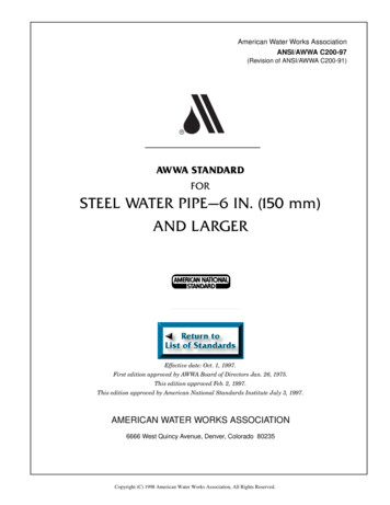
Design OverviewThe basic criterion for the design of a steel pipe is resistance to internal pressure. Once that criterionhas been met, the resulting wall thickness is verified for adequacy with respect to other performancecriteria such as: External loads Handling Buckling (external pressure)For many projects, the wall thickness recommended to allow reasonable handling of the pipe satisfies the remaining performance criteria as well. AWWA Manual M11, Steel Water Pipe: A Guide forDesign and Installation, and American Iron and Steel Institute’s Welded Steel Pipe Design Manualprovide excellent information for the design professional.General PrinciplesTypically, water pipe should be designed based on the internal working and transient pressure service conditionsto which it will be subjected during its lifetime. Additionalservice conditions to evaluate include external operatingand transient or live load, and vacuum pressures. In addition, adequate stiffness is needed for ease of handlingpipe in the facility and in the field. The following guidelines focus on the design and calculation of the requiredpipe wall thickness based on these service conditions.Most plate and sheet manufacturers today produce very high quality steel using the continuouscasting process. This process yields a fine grain, “killed” (deoxidized) steel that is metallurgically homogeneous and exhibits excellent ductility. Steel pipe is typically manufactured from one ofseveral steels available in varying strengths as listed in Table 2.1. Typically, higher strength steel hasa marginally higher cost. For applications where the operating or design pressure exceeds 175 psi(1.1 MPa), an analysis should be performed to evaluate the potential cost or other advantages ofusing steel with yield strength in excess of 42 ksi (290 MPa). For the same pressure requirements,the increase in cost for using a higher strength material is typically less than the costs associatedwith the increased wall thickness required for a lesser strength steel. The use of higher strengthsteel normally has little benefit, though, for lower pressure, buried applications. In low-pressuredesigns, handling or other considerations — rather than internal pressure — will most often govern theselection of the pipe wall thickness.2
Table 2.1ASTM MaterialDesignation1GradeMinimum YieldStrength ksi(MPa)Minimum TensileStrength ksi(MPa)Steel Sheet (Coil or Flat)A139BCDE35 (242)42 (290)46 (315)52 (360)60 (415)60 (415)60 (415)66 (455)36 (248)42 (290)50 (345)30 (205)32 (220)35 (240)38 (260)58 (400)60 (415)65 (449)55 (380)60 (415)65 (450)70 (485)Steel r steel material types, including various grades of ASTM A1011 or ASTM A1018, are available upon request. Contact an AMERICANrepresentative for availability of a particular steel material type not listed above.When designing a steel pipe, the main design consideration is the pipe’s ability to withstand internalpressure. After a wall thickness has been determined based on internal pressure, including bothoperating and transient pressures, that thickness must be checked to determine its adequacy forresisting external loads and the minimum thickness required for handling. External loads includethose due to backfill material and potential vehicles, construction equipment, or railroad cars, andbuckling forces resulting from external pressure. As required, the composite wall thickness for nonburied pipe (steel thickness plus cement lining thickness, when applicable) can be increased; or,for buried steel pipe, the stiffness of the pipe/backfill system can be increased to resist the externalloads. The most common and cost effective method used to increase the pipe/backfill system stiffness is to improve the quality of the backfill material and/or the level of backfill compaction.3
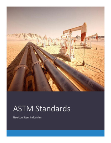
Internal PressureDesign for internal pressure requires a two-part stress analysis. Each part of the analysis is governedby the application of the Barlow hoop stress formula, reconfigured as follows:tWhere: PD/2StPDS minimum, nominalspecified wall thickness,in. (mm) pressure, psi (MPa) steel cylinder outsidediameter*, in. (mm) allowable design stress psi, (MPa)tP*Note: Use of the outside diameter is a conservative design approach.The wall thickness should first be calculated based on the maximum sustained internaloperating (working) pressure, and then calculated based on the larger of the maximum sustainedoperating plus transient pressure, or the field-test pressure. As noted in the AWWA Manual M11, whencalculating thickness due to the operating pressure, the design stress should be limited to 50%of the minimum yield strength of the steel. In addition, when calculating thickness due to theoperating plus transient, or test pressure, the design stress should be limited to 75% of the minimumyield strength of the steel.HandlingFor pipe with shop-applied cement mortar lining, the minimum required wall thickness based onhandling should be limited by a Dn/t (nominal diameter/thickness) ratio of 240. For pipe with a sprayapplied flexible lining or no lining at all, the minimum required wall thickness based on handlingshould be limited by a Dn/t ratio of 288.Cement mortar lined pipe:Dn/t 240Spray-applied flexible liningor bare pipe:Dn/t 2884
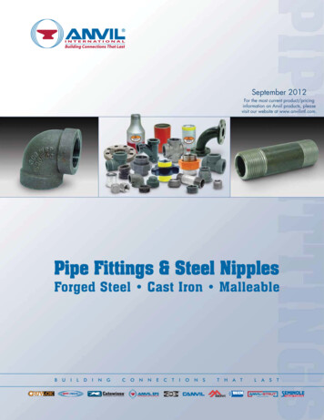
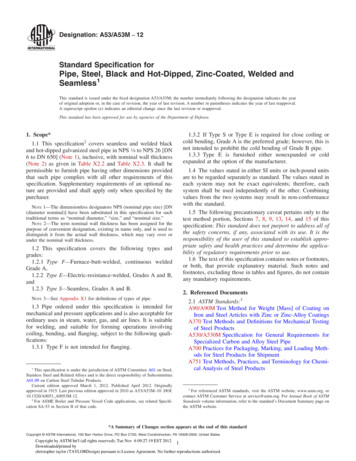
External LoadingFor buried pipe, resistance to external loading is a function of pipe stiffness and passive soilresistance under and adjacent to the pipe. These two factors work in unison to create a pipe/backfillsystem whose stiffness resists the earth and live loads to which the pipe is subjected. The estimatedhorizontal deflection of a buried pipe can be calculated by the Iowa deflection formula, as follows: x DlKWr3EI 0.061E′r3Where: xDlKW horizontal deflection of pipe, in. (mm) deflection lag factor bedding constant external load per unit length of pipe (WE WL),lb/in. (N/mm)Where: WE earth load (dead load)WL live loadr mean radius of pipe shell, in. (mm)EI pipe wall stiffness, in-lb (mm-N)*Where: E modulus of elasticity [30x106 psi (207x103 MPa) for steel and4x106 psi (27.6x10³ MPa) for cement mortar]I transverse moment of inertia per unit length of pipe wall,in.3 (mm3)E′ modulus of soil reaction, lb/in.2 (N/mm2)Total load Wradi us100 r *Under load, the individual components of the pipe wall(steel, mortar lining and, when applicable, mortar coating) act together as laminated rings. The combinedaction of these elements increases the overall momentof inertia of the pipe, over that of the steel cylinder alone.The total stiffness, EI, is equal to the sum of all individualvalues: EsIs ElIl EcIc.xx22As noted above, the stiffness of the pipe/backfill system– pipe stiffness and passive soil resistance of the backfill– plays the key role in predicting deflection. The system is5
the denominator of the Iowa deflection equation, where pipe stiffness is the EI term and passivesoil resistance of the backfill is the 0.061E′r3 term. History has shown that, in general, the mosteffective improvement in the system’s ability to resist loading comes from increasing the passive soilresistance of the backfill and not the pipe stiffness. When the calculated deflection exceeds theallowable, improvement of the backfill material or level of compaction should be the primeconsideration versus an increase of the steel wall thickness. Following are explanations of the termsused in the equation above. x, Predicted Deflection – Because steel pipe is designed as a flexible conduit, significantdeflection can occur without damaging the product. Common practice has limited thecalculated deflection to 5%, although larger deflections may not affect pipe performance. Deflectionlimitations are a function of the rigidity of the specific lining and coating being used. Forspray-applied flexible linings and flexible coatings, AWWA M11 recommends a maximum allowabledeflection of 5%. The AWWA recommendation for cement mortar lined pipe with a flexible coating is3%. To limit coating cracks in a cement mortar coated pipe, AWWA recommends limiting deflectionto 2%. A deflection limitation of 2% is also generally recommended for a field applied cement mortarlining due to lining equipment limitations.In summary:Cement Mortar Lining x Cement Mortar Coating 2% of pipe diameterCement Mortar Lining x Flexible Coating 3% of pipe diameterFlexible Lining x Flexible Coating 5% of pipe diameterDl, Deflection Lag Factor – The deflection lag factor is a subjective multiplier used to define theprojected long-term deflection of a pipe as a function of the calculated deflection at time of installation. With a well compacted backfill around the pipe cylinder, it is common practice to use a factorof 1.0. This is especially true for a pressurized pipe, as the internal pressure will tend to round thepipe while in service. As a result, additional settling of the backfill over time will improve the materialconsolidation around a circular cylinder. This improvement in consolidation will increase, not decrease, the system’s capacity to resist external load.K, Bedding Constant – The bedding constant is a reflection of the influence of the bedding angleon the pipe’s resistance to external load. (The bedding angle is a measurement in degrees of thecircumferential contact of the bottom of the pipe with the trench bedding material.) With improvedbedding below the springline (50% of pipe outside diameter), support to the pipe is improved resulting in decreased deflection. The range of K is from 0.110 for pipe laid on a flat trench bottom (nobedding) to 0.083 for the pipe bedded to the springline. For typical conditions encountered with theinstallation of steel pipe, a conservative design value of K is 0.10.6
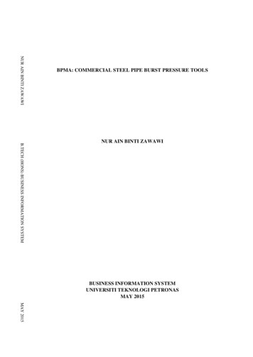
WE, Earth Load (Dead Load) – When buried in an embankment or wide trench, the settlement ratiofor a flexible conduit such as steel pipe is assumed to be zero. As such, the prism of soil directlyover the pipe is used as the resultant earth load. The prism dimensions are represented as a widthequal to the pipe outside diameter, a height equal to the depth of cover over the top of the pipe, anda unit length of 1 in. This method is conservative as no consideration is given to potential archingaction of the backfill material relative to the adjacent native soil. A conservative density of the backfillmaterial, gE, is typically taken as 120 lb/ft3 for determination of the earth load.WL, Live Load – Live loads are typically a result of vehicle wheels, equipment wheels or tracks,or railroad car wheels. The accepted values for vehicle and railroad induced live loads (standardHS-20 highway and E-80 railroad loading) are listed in Table 2.2. If present, live loads resultingfrom movement of heavy equipment over pipelines must be given special consideration. For extreme loading conditions reference: Spangler, M.G. & Handy, R.L., Soil Engineering, Harper & Row,Publishers, New York, NY (4th ed., 1982); or contact AMERICAN.EI, Pipe Stiffness – As noted previously, the pipe stiffness EI is equal to the sum of all individualstiffness values for each of the laminar rings of the pipe structure; that is EsIs plus ElIl plus EcIc, forthe cylinder, cement mortar lining, and cement mortar coating respectively. The stiffness of each ofthe rings is calculated using the modulus of elasticity of the component, in psi, and the moment ofinertia as a per unit length value, defined as t3/12.E′, Modulus of Soil Reaction – The modulus of soil reaction is anempirical measurement of a given compacted soil’s resistanceto movement. Modification of the value of E′, accomplished byimproving the backfill material and/or improving the level ofcompaction, is the most common and most cost effective way toimprove the stiffness of the pipe/backfill system. In recent years,designers have taken note of the inherent increase in the E′ value relative to increased depth ofcover. Most notably, James D. Hartley and JamesM. Duncan of the University of California, Berkeley,published Evaluation of the Modulus of Soil Reaction, E′, and Its Variation with Depth. Their researchdefined E′ as a function of soil type, degree of compa
AWWA Manual M11, Steel Water Pipe: A Guide for Design and Installation, and American Iron and Steel Institute’s Welded Steel Pipe Design Manual provide excellent information for the design professional. General Principles Typically, water pipe should be designed based on the in - ternal working and transient pressure service conditions to which it will be subjected during its lifetime .