Transcription
Offshore Structural DesignDetail EngineeringFixed PlatformsM.ANBARASAN1
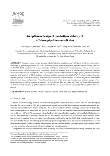
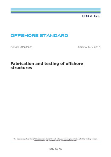
Components of Fixed Platforms2
Design of structures In-place Phase (Piles, Jacket ,Deck Integral)Three types of analysis are performed:Survival state----- wave/current/wind attack with 50 or100 years recurrence period.Operational state--- wave/current/wind attack with 1 or 5years recurrence period, under full operation.Fatigue assessment for design life.Accidental.Above analyses are performed on the complete andintact structure.Assessments at damaged structures, e.g. with onemember deleted, and assessments of collision situationsare occasionally performed.3
Design of structures(contd) Majority of structural analyses arebased on the linear theory of elasticityfor total system behaviour. Dynamic analysis is performed for thesystem behaviour under wave-attack ifthe natural period exceeds 3 seconds.4
Structure GeometryJacket configuration depends1.2.3.4.5.Size of deckWater depthGeotechnical reportsNo. of conductorsAppurtanances : They areRisers , Boat Landing , Barge bumpersRiser guards, Pumps or Caissons.5
Computer Model Preparation- Jackets Jacket structure shall be modelled as a 3D space frame. All primary and secondarytubular members shall be modelled.Risers & Caissons shall be modelled as structural elements that attract wave loads(without contribution to the jacket stiffness). They should be linked to the jacket ina way that is consistent with their guide and anchor arrangements.Conductors shall be modelled down to mudline level where they can be assumedpinned. Linear dependencies shall be provided at relevant guide levels such thatconductors do not contribute to the structural stiffness of the jacket.Boat landing primary members shall be modelled such that they attract waveloads. The effects of secondary members shall be considered by modellingadditional masses and modifying the hydrodynamic coefficients of primarymembers. Boat landing models shall be connected to the jacket models such thatthey correctly reflect the state of the connection/releases between two structures.6
Computer Model Preparation- Jacket(contd.) Jacket Appurtenances including mudmats, anodes,walkways, ladders and fenders shall be modelled aseither structural masses or increased density onassociated members. The contribution of these membersto hydrodynamic forces shall be considered by modifyingdrag and mass coefficients of main members Grouted pile sleeves and members with ring stiffenersshall be modelled as equivalent members with similarstiffness and correct structural mass. Joint eccentricities shall be modelled based on therequirements of API-RP2A .7
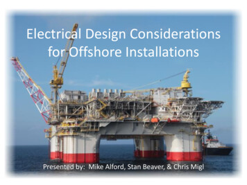
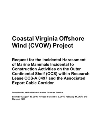
Well Head Platform8
Codes and Standards– API-RP2A: American Petroleum Institute Recommended practice forplanning, designing and constructing fixed offshore platforms Thestructural offshore code,Regulations of a major certifying authority.– DnV: Rules for the classification of fixed offshore installations.– AISC: Specification for the design, fabrication and erection of structuralsteel for buildings. American Institute of Steel Construction . Widelyused structural code– AWS D1.1-90: Structural Welding Code - Steel.American Welding Society 1990. The structural offshore welding code.– Marine Operations: Standard for insurance warranty surveys in marineoperations. Regulations of a major certifying authority.– ABS: Rules for building and classing offshore installations, Part 1Structures.American Bureau of Shipping 1983.Regulations of a major certifyingauthority.– BV: Rules and regulations for the construction and classification ofoffshore platforms. Bureau Veritas Regulations of a major certifyingauthority.9
Data Requirement Environmentwater depth at locationsoil, at sea bottom and in-depthwind speed, air temperaturewaves, tide and storm surge, currentice (fixed, floes, icebergs) (not applicable for this part ofworld)EarthquakesDeck loads (Operating & Extreme)Dead loads,Live Loads,Equipment Loads10
Platform Data(Typical)Design life 25 yearsWind loads Inplace of Jacket ---- 1Hr averageDeck Inplace ---------- 1 Min AverageModules/Frame local- 3Sec GustCantelever struct ----- 3 Sec GustZones:Atmospheric ----- 6.00 upwardsSplash----- -1.8 to 6.0Submerged ------ -1.8 to MudlinePlat form location Northing Easting Ref.PointWater depth55.0 m from MSLLowest Astronomical Tide ----- -0.183m11
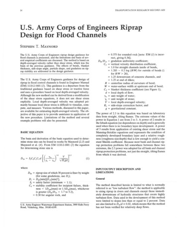
Extreme Storm Parameters12
Operating Storm Parameters13
Installation Parameters14
Envormental Parameters for Fatigue design15
Wave exceedance data (Fatigue design)16
Material Properties Design properties of steel shall be taken asfollows:Density (ρ) 7850 kg/m3Modulus of Elasticity (E) 210 x 106 kN/m2Shear Modulus (G) 80.9 x 10⁶ kN/m2Poisson’s Ratio (ν) 0.3Coefficient of Thermal Expansion (α) 12.0 x 10 –6 / C17
18
Corrosion allowanceAdditional wall thickness in the form of corrosion allowance shall beprovided for the jacket members in the splash zone Jacket legs, bracing, conductor and caissons 12mm Pipe casings and sump caissons (wrapped) 12mm wrapped plate Fenders, bumpers and boat landing members 6 mm Note: The extra thickness for corrosion allowance shall not beincluded in calculatingstresses in members or joints. For these members/joints, theallowance shall bededucted from the outside diameter of the tube. In general, thetubular member wallthickness in the splash zone shall not be less than 25mm.Alternatively Monel sheathing provided in Splash zones.19
Cathodic ProtectionAll jacket members below the water lineshall be protected against corrosion usingsacrificial anodes. The protection systemshall be designed based on therequirements of DNV-RP B401Anode properties as per specification20
Loads The following loads shall be considered when a platform is in permanent condition:Dead Loads: Weight of the platform structure and appurtenances, permanentequipment and pipes, dead weight of modules, cranes and helideck.Functional Loads: Loads induced by platform operation like weight of the liquids inpipes/tanks, thermal loads, drilling loads, loads induced by helicopter landing andvessel mooring, dynamic loads due to vibration of equipment and loads due to craneoperation.Live Loads: Weight of the personnel, movable equipment and loads due to materialhandling.Environmental Loads: Loads induced by the action of waves, currents, winds,earthquake, and temperature fluctuations.Accidental Loads: Loads induced by accidental vessel collision, fire, explosion, waveslam and dropped objects.21
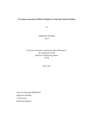
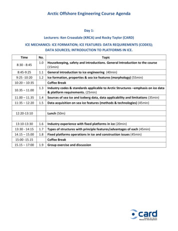
Typical Deck Loading22
Wind Load calculationsWind loads act on the portion of a platform above the water level, as well ason any equipment, housing, derrick, etc. located on the deck. An importantparameter pertaining to wind data is the time interval over which windspeeds are averaged. For averaging intervals less than one minute, windspeeds are classified as gusts. For averaging intervals of one minute orlonger they are classified as sustained wind speeds.The wind velocity profile may be taken from API-RP2A [2]:Vh/VH (h/H)1/n (1)where:Vh is the wind velocity at height h,VH is the wind velocity at reference height H, typically 10m above meanwater level,1/n is 1/13 to 1/7, depending on the sea state, the distance from land andthe averaging time interval. It is approximately equal to 1/13 for gusts and1/8 for sustained winds in the open ocean.From the design wind velocity V(m/s), the static wind force Fw(N) actingperpendicular to an exposed area A(m2) can be computed as follows23
Wind loads (cont.)Fw (1/2) r V2 Cs A (2)where:r is the wind density (r » 1.225 Kg/m3)Cs is the shape coefficient (Cs 1,5 for beams and sides of buildings,Cs 0,5 for cylindrical sections and Cs 1,0 for total projected area ofplatform).Shielding and solidity effects can be accounted for,by designer’s judgementFor combination with wave loads, the DNV and DOE-OG rulesrecommend the most unfavourable of the following two loadings:a. 1-minute sustained wind speeds combined with extreme waves.b. 3-second gusts.API-RP2A distinguishes between global and local wind load effects. Forthe first case it gives guideline values of mean 1-hour average wind speedsto be combined with extreme waves and current. For the second case itgives values of extreme wind speeds to be used without regard to waves.24
Wave Slam (Misc') Wave slam shall be considered for members in the splash zone.The wave slam loadshall be calculated based on the equation presented below. The APIallowable stresses can be increased by 33% for the design ofmembers and connections.F 0.5 ρ.Cs.Us2 whereUs Velocity of the water surface normal to the member surface (m/s)Cs Slam coefficient (3.5 for tubulars, 5.0 for flat plates)ρ Water density (kg/m3)In designing the members for wave slam, consideration shall begiven to dynamicamplifications due to wave impact. In this case a minimum dynamicamplification of2.0 shall be used in calculating the bending moments at the memberends and midspan.25
Wave LoadsThe wave loading of an offshore structure is usually themost important of all environmental loadings for whichthe structure must be designed. The forces on thestructure are caused by the motion of the water due tothe waves which are generated by the action of the windon the surface of the sea. Determination of these forcesrequires idealisation of the wave surface profile and thewave kinematics given by an appropriate wave theory.The computation of the wave forces on individualmembers and on the total structure, from the fluidmotion.26
27
CurrentThere are tidal, circulation and storm generatedcurrents. When insufficient data in criteria,current velocities may be obtained from varioussources, e.g. Appendix A of DNV. In platformdesign, the effects of current superimposed onwaves are taken into account by adding thecorresponding fluid velocities vectorially. Forslender members, cyclic loads induced by vortexshedding may also be important and should beexamined locally.28
Other parameters Marine GrowthMarine growth is accumulated on submerged members. Its maineffect is to increase the wave forces on the members by increasingnot only exposed areas and volumes, but also the drag coefficientdue to higher surface roughness. In addition, it increases the unitmass of the member, resulting in higher gravity loads and in lowermember frequencies.Marine growth consideration 3.00m to -30.00 m-30.0m to Mudline10 cm5 cm TidesTides affect the wave and current loads indirectly, i.e. through thevariation of the level of the sea surface. The tides are classified as:(a) astronomical tides(b) storm surges - caused by the combined action of wind andbarometric pressure differentials during a storm. The combinedeffect of the two types of tide is called the storm tide.29
EarthquakeOffshore structures in seismic regions are typicallydesigned for two levels of earthquake intensity:The strength level and the ductility level earthquake. Forthe strength level earthquake, defined as having a"reasonable likelihood of not being exceeded during theplatform's life" (mean recurrence interval 200 - 500years), the structure is designed to respond elastically.For the ductility level earthquake, defined as close to the"maximum credible earthquake" at the site, the structureis designed for inelastic response and to have adequatereserve strength to avoid collapse.30
Preservice condion loadsLoadout Forces These are forces generated when the jacket is loaded from thefabrication yard onto the barge. If loadout is done by skidding thestructure onto the barge, a number of static loading conditions mustbe considered, with the jacket supported on its side. Such loadingconditions arise from the different positions of the jacket during theloadout phases, from movement of the barge due to tidalfluctuations and from possible support settlements. Since movementof the jacket is slow, all loading conditions can be taken as static.Typical values of friction coefficients for calculation of skiddingforces are the following:steel on steel without lubrication. 0,25steel on steel with lubrication. 0,15steel on teflon. 0,10teflon on teflon. 0,0831
Preservice condion loads(cont.) Lifting ForcesLifting forces are functions of the weight of the structural component beinglifted, the number and location of lifting eyes used for the lift, the anglebetween each sling and the vertical axis and the conditions under which thelift is performed . All members and connections of a lifted component mustbe designed for the forces resulting from static equilibrium of the liftedweight and the sling tensions. API-RP2A recommends that in order tocompensate for any side movements, lifting eyes and the connections to thesupporting structural members should be designed for the combined actionof the static sling load and a horizontal force equal to 5% this load, appliedperpendicular to the padeye at the centre of the pin hole. All these designforces are applied as static loads if the lifts are performed in the fabricationyard. If, however, the lifting derrick or the structure to be lifted is on afloating vessel, then dynamic load factors should be applied to the staticlifting forces.Lifts made offshore API-RP2A recommends two minimum values ofdynamic load factors: 2,0 and 1,35. The first is for designing the padeyes aswell as all members and their end connections framing the joint where thepadeye is attached, while the second is for all other members transmittinglifting forces.32
Preservice condion loads(cont.)Transportation ForcesThese forces are generated when platformcomponents (jacket, deck) are transpo
– API-RP2A: American Petroleum Institute Recommended practice for planning, designing and constructing fixed offshore platforms The structural offshore code, Regulations of a major certifying authority. – DnV: Rules for the classification of fixed offshor e installations. – AISC: Specification for the design, fabrication an d erection of structural steel for buildings. American Institute .