Transcription
PDH Course S150Structural Steel WeldingSemih Genculu, P.E.2007PDH Center2410 Dakota Lakes DriveHerndon, VA 20171-2995Phone: 703-478-6833Fax: 703-481-9535www.PDHcenter.comAn Approved Continuing Education Provider
www.PDHcenter.comPDH Course S150www.PDHonline.orgStructural Steel WeldingSemih Genculu, P.E.Arc welding requires striking a low-voltage, high-current arc between an electrode and the workpiece (base metal). Theintense heat generated with this arc melts the base metal and allows the joining of two components. The characteristic ofthe metal that is being welded and the joint type (i.e. groove, fillet, etc.) dictates the welding parameters and the procedurethat needs to be followed to obtain a sound weld joint.Typical Arc Welding Processes:Shielded metal arc welding (SMAW): Shielded metal arc welding, which is also known as stick welding, is the mostwidely used process. The arc is struck between the metal to be welded and a flux coated consumable electrode. Thefluxes are mostly made from mineral components and cover the hot weld deposit and protect it from the environment. Thesolidified glassy product, slag should be removed by chipping or with a wire brush.Gas metal arc welding (GMAW): This process is also referred to as metal inert-gas (MIG) welding uses an uncoatedcontinuous wire. The weld area is shielded from contamination by the gas that is fed through the welding torch. Themode of metal transfer (spray, globular, short-circuiting, pulsed-arc) is varied by adjusting the amperage and the shieldinggases used depending on the welding position and the type of joint. Semih GenculuPage 2 of 18
www.PDHcenter.comPDH Course S150www.PDHonline.orgFlux-cored arc welding (FCAW): The shielding gases and slag are provided by the decomposing flux that is containedwithin the electrode. Auxiliary shielding is also used in certain instances where deeper penetration is needed.Gas tungsten arc welding (GTAW): Also known as tungsten inert-gas (TIG), the process uses a non-consumableelectrode. The shielding gas is again fed through the welding torch. Welding may be accomplished without the addition offiller metal, which is advantageous especially for thin walled parts.Shielding gases:The primary purpose of the shielding gas is to protect the molten weld from contamination and high temperature oxidationby the surrounding atmosphere. Although plain inert gases may not be suitable for all applications, mixtures with reactivegases (i.e. oxygen, nitrogen, hydrogen and carbon dioxide) in controlled quantities will produce stable and relativelyspatter-free metal transfer.Argon: Argon by itself is frequently used for MIG welding of nonferrous metals. A mixture of argon and oxygen or argonand carbon dioxide is usually preferred for ferrous metals. The high-density arc that is created by argon permits theenergy to go into the work piece as heat resulting in a narrow bead width with deep penetration.Helium: has higher thermal conductivity and arc voltage than argon, which causes it to produce broader weld beads.Because helium is a very light gas, higher flow rates must be used for effective shielding. This characteristic is beneficial inoverhead welding.Carbon dioxide: is widely used for steels. Higher welding speed, better joint penetration and sound deposits with goodmechanical properties can be achieved. Carbon dioxide is not an inert gas as the argon and helium and breaks down intocarbon monoxide and free oxygen under the heat of the arc. The oxygen is used to superheat the weld metal transferringacross the arc.Arc welding defects:Most welds contain defects (porosity, cracks, slag inclusions, etc.). The question is to determine if they are significantconsidering the application. Typically, the applicable codes or standards specify the maximum allowable limits of thesetypes of defects in a weld based on the application. Sometimes discontinuities that may not affect mechanical propertiesmay reduce corrosion performance. The properties of the heat-affected zone (HAZ) are one of the significant factors toconsider when evaluating the soundness of the weld joint. The HAZ may be considered as a discontinuity because of themetallurgical alterations as a result of the welding heat, which causes very rapid heating and cooling rates. Grain growth,phase transformations (i.e. brittle untempered martensite which can form depending on the cooling rate and the chemicalcomposition of the base material), formation of precipitates or overaging (loss of strength in precipitation-hardened alloys)all has a drastic effect on the properties of the HAZ. It is possible to improve the weld zone properties by controlling the Semih GenculuPage 3 of 18
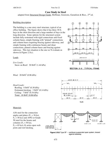
www.PDHcenter.comPDH Course S150www.PDHonline.orgcooling rate. This may be accomplished by slowing the cooling rate down either by increasing the heat input or preheating(i.e. heating the metal up before welding).Porosity: Gas pockets are formed in the weld metal when they are entrapped during solidification. Molten steel readilyabsorbs hydrogen, carbon monoxide and other gases to which it is exposed. Since these are not soluble in solid metal,they are expelled as the metal solidifies. Standard shielded arc electrodes with organic coating such as E6010 produce anatmosphere around the arc that contains hydrogen, a notable contributor to porosity. When using such electrodes, weldingshould be done slowly to allow the gases time to escape since too high of a travel speed causes rapid solidification of theweld metal leading to porosity. Weld joint cleanliness is also crucial in avoiding porosity since moisture, oil, paint, or ruston the base metal may also cause porosity by introducing oxygen or hydrogen into the weld metal. Employing someminimum preheat temperature is often useful to remove condensation. It is also necessary to maintain the fluxes and thecoated electrodes dry to avoid moisture pick-up. They are typically kept in an oven at approximately 250ºF, or if thehermetic seal is broken on the containers then the consumables (e.g. welding rods) should be baked at highertemperatures to drive off the moisture and restore the low hydrogen characteristics. Common causes and remedies ofporosity are listed below along with a macrograph of a fillet weld containing porosity. An illustration of a groove weld whichexhibits cluster porosity is also included with its corresponding radiograph.Porosity: gas pockets or voids that are found in weldsCausesRemediesExcessive hydrogen, nitrogen oroxygen in welding atmosphereUse low hydrogen welding process, fillermetals high in deoxidizers, increase shieldinggas flowHigh solidification rateUse preheat or increase heat inputDirty base metalClean joint faces and adjacent surfacesDirty filler wireUse clean wire and store fillers in a clean areaImproper arc length, welding current orelectrode manipulationModify welding parameters and techniquesVolatilization of zinc from brassUse copper-silicon filler, reduce heat inputPorosity: gas pockets or voids that are found in weldsCausesRemediesGalvanized SteelUse E7010 electrode and manipulate the archeat to volatilize the galvanizing (zinc) aheadof the molten weld poolExcessive moisture in electrodecovering or on joint surfacesUse recommended procedures for baking andstoring electrodesHigh sulfur base metalUse electrodes with basic slagging reactions Semih GenculuPage 4 of 18
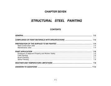
www.PDHcenter.comPDH Course S150www.PDHonline.orgSlag inclusions: The oxides or other nonmetallic inclusions that become entrapped in the weld metal. They may be causedby contamination or inadequate cleaning between weld passes. The slag derived from fluxes employed during weldingneeds to be cleaned between weld passes (in multi-pass operations) using a chipping hammer or a wire brush. Themacrograph below illustrates a successful multipass weld joint. Semih GenculuPage 5 of 18
www.PDHcenter.comPDH Course S150www.PDHonline.orgTungsten inclusions: In the TIG process, the touching of the electrode to the weld metal may cause transfer of thetungsten particles into the weld metal. These inclusions are detected by x-ray and show up as bright particles since theyare much denser than the steel. An example is shown below where the x-ray revealed the tungsten inclusions. Semih GenculuPage 6 of 18
www.PDHcenter.comPDH Course S150www.PDHonline.orgIncomplete fusion/penetration: Although these terms are sometimes used interchangeably, lack of fusion occurs when theweld and base metal fail to adequately fuse together. It can also be encountered between weld passes. It may be causedby not raising the temperature of the base metal or previously applied weld metal to the melting point or failure to removethe slag or mill scale. Lack of penetration is typically due to inadequate heat input for the particular joint that is beingwelded and is usually seen at the sidewalls of a weld joint, between weld passes or at the root of the weld joint. Theshielding gas can also influence the penetration; typically helium is added for nonferrous metals and carbon dioxide isadded for ferrous metals (to argon) to increase penetration. The first macrograph below shows an acceptable single passfillet weld profile with adequate base metal penetration and root fusion. The second macrograph shows lack of penetrationto the root in a double welded joint, and the third macrograph illustrates lack of penetration to one of the members. Thefinal illustration shows the sketch of another variation of incomplete root penetration and its appearance on an x-ray film(radiograph). Semih GenculuPage 7 of 18
www.PDHcenter.comPDH Course S150www.PDHonline.orgUndercut: This occurs when a groove that is formed adjacent to the weld as a result of the melting of the base metalremains unfilled. An example is shown in the macrograph below (at the toe of the fillet weld) along with the appearance ofthis type of defect on a radiograph of a groove weld. Semih GenculuPage 8 of 18
www.PDHcenter.comPDH Course S150www.PDHonline.orgWeld profile: The profile of a finished weld may have a considerable effect on the performance under dynamic loadingconditions. Overlap, excessive reinforcement or mismatch can provide stress concentration points where fatigue crackscan initiate. Typical unacceptable butt and fillet weld profiles are shown below along with an example of poor fit-up(mismatch): Semih GenculuPage 9 of 18
www.PDHcenter.comPDH Course S150www.PDHonline.orgMacrograph showing poor fit-up (butt weld)Arc strikes: They are caused by the unintentional melting of the base metal outside the weld deposit area by the weldingarc. It can create localized hard or soft spots, cracking or undercut. Another welder-induced defect is weld spatter. Itusually occurs when excessive welding current, long arc or welding voltage is used. Below macrograph shows arc strikesnear a fillet weld. Semih GenculuPage 10 of 18
www.PDHcenter.comPDH Course S150www.PDHonline.orgCracks: Cracks are the most serious type of weld defects that can lead to catastrophic failures in service. There are manydifferent types of cracks. One way of categorizing them is as surface or subsurface cracks. Another way would be as hot(which occur during or immediately after the weld is made) or cold (cracks that occur after the weld has cooled to roomtemperature-sometimes within hours or days). In general, weld or heat- affected zone cracks indicate that the weld or thebase metal has low ductility and that there is high joint restraint. Many factors can contribute to this condition such as rapidcooling, high alloy composition, insufficient heat input, poor joint preparation, incorrect electrode type, insufficient weld sizeor lack of preheat. Some common causes and remedies are given in table below.Cracks: Hot and cold cracks or microfissures can form in the weld or the base metalCausesHighly rigid jointExcessive dilution (change in chemicalcomposition of a weld deposit causedby the admixture of the base metal)RemediesPreheatRelieve residual stresses mechanicallyMinimize shrinkage stresses using backstepsequence (a longitudinal sequence in whichweld passes are made in the directionopposite to the progress of welding)Change welding current and travel speedWeld with covered electrode negative; butterthe joint faces prior to welding (buttering isdepositing surfacing metal to providemetallurgically compatible weld metal to thesubsequent weld passes)Poor fit-upReduce root openingSmall weld beadIncrease electrode size, raise welding current,reduce travel speedHigh sulfur base metalUse filler metal low in sulfurExcessive distortionChange to balanced welding on both sides ofjointCrater crackingFill crater before extinguishing the arcHigh residual stressesRedesign weldment, change weldingsequence, apply intermediate stress reliefHigh hardenabilityPreheat, increase heat input, heat treatwithout cooling to room temperaturePhotograph illustrating crater cracking resulting from abrupt weld terminationin an aluminum weld (MIG process) Semih GenculuPage 11 of 18
www.PDHcenter.comPDH Course S150www.PDHonline.orgThe effect of carbon equivalent:The carbon equivalent (C.E.) may be considered as the main factor in estimating preheat need. Generally, the higher thecarbon content of a steel, the greater the tendency to form a hard and brittle HAZ. This necessitates the use of preheatand low hydrogen electrodes. Carbon, however, is not the only element that influences hardenability. Other elements insteel also are responsible for the hardening and loss of ductility that occur with rapid cooling. One of the various empiricalformulas used to determine carbon equivalent is given in the Structural Steel Welding Code (AWS D1.1) as follows:%C.E. %C % (Mn Si)/6 % (Cr Mo V)/5 % (Ni Cu)/15The approximate recommended preheat temperatures based on C.E. are:For up to 0.45% preheat is optional0.45-0.60% 200-400ºFOver 0.60% .400-700ºFUsually a steel that requi
www.PDHcenter.com PDH Course S150 www.PDHonline.org formulas used to determine carbon equivalent is given in the Structural Steel Welding Code (AWS D1.1) as follows: