Transcription
IJRET: International Journal of Research in Engineering and TechnologyeISSN: 2319-1163 pISSN: 2321-7308OPTIMIZED DESIGN & ANALYSIS OF STEEL PIPE RACKS FOR OIL& GAS INDUSTRIES AS PER INTERNATIONAL CODES &STANDARDSNitesh J Singh1, Mohammad Ishtiyaque21P.G Student, Civil Engineering Department, M.I.T, Maharashtra, India2Professor, Civil Engineering Department, M.I.T, Maharashtra, IndiaAbstractOptimized Design of Steel Pipe rack supporting structures in an Oil & Gas Industry is complex as one of the most important partsof structural systems for safe and stable production processes have been studied in this paper. In this thesis we have tried todesign the Steel Pipe rack as per International standards which has been accepted most part of the world. Transverse direction isconsidered as Moment frame and Longitudinal as Shear connection to tackle the loading as per piping stress analysis. Planbracing is provided in top and bottom tier so that lateral deflection can be optimized and distributed to the Anchor bay location.Anchor bay is provided in every Steel structure at maximum interval of. Vertical bracing is provided up to top tier on bothTransverse and longitudinal direction so that all the lateral forces get transferred through this vertical bracing to the base.Fireproofing criteria has been also considered as per International standard to tackle fire hazard. The Structure has beendesigned in two parts as Strength design and Serviceability design for proper analysis and design of structure. Base Plate andPedestal has been designed as per AISC codes considering support reactions. Then the Footing is designed in Staad Foundationby importing Staad model to get optimized footing design.Keywords: Oil & Gas, Steel Pipe Rack, Transverse, Longitudinal Direction, Fireproofing, Staad Foundation, AISCCodes etc ----------------------------------------1. INTRODUCTIONPipe networks are considered as main components ofindustrial complexes like refineries and petrochemicals thattransfer fluid and gas and any damage in their structuresmay be dangerous.Although the value of stability analysis has long beenrecognized, implementation in design has historically beendifficult as calculations were performed primarily by hand.Various methods were created to simplify the analysis andallow the engineer to partially include the effects of stabilityvia hand calculations. However, with the development ofpowerful analysis software, rigorous methods to account forstability effects were developed. While stability analysiscalculations can still be done by hand, most engineers nowhave access to software that will complete a rigorousstability analysis. Stability analysis is a broad term thatcovers many aspects of the design process. According to the2010 AISC Specification for Structural Steel Buildings(AISC 360-10) stability analysis shall consider the influenceof second order effects (P-Δ and P-δ effects), flexural, shearand axial deformations, geometric imperfections, andmember stiffness reduction due to residual stresses.The main reason for life loss is collapse of structures It issaid that natural calamities itself never kills people; it isbadly constructed structure that kill. Hence it is important toanalyze the structure properly for different natural calamitieslike earthquake, cyclones, floods and typhoons etc.1.1 Wind EffectASCE 7-05 provides very little, if any guidance forapplication of wind load for pipe racks. The mostappropriate application would be to assume the pipe rack isan open structure and design the structure assuming a designphilosophy similar to that of a trussed tower. See Table 3-1below for Cf, force coefficient. This method requires theengineer to calculate the ratio of solid area to gross area ofone tower face for the segment under consideration. Thismay become very tedious for pipe rack structures becauseeach face can have varying ratios of solids to gross areas.Tower Cross SectionCfSquare4.0ε2-5.9ε 4.03.4ε2-4.7ε 3.4TriangleVolume: 05 Issue: 10 Oct-2016, Available @ http://ijret.esatjournals.org16
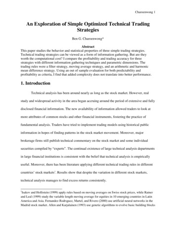
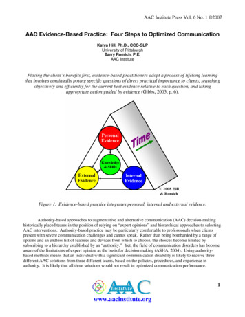
IJRET: International Journal of Research in Engineering and TechnologyForce coefficient, Cf for open structures trussed towers(Adapted from ASCE 7-05)The tributary area for structural steel members and otherattachments should be based on the projected area of theobject perpendicular to the direction of the wind. Becausethe structural members are typically spaced at greaterdistances than pipes, no shielding effects should beconsidered on structural members and the full windpressures should be applied to each structural member.pipe rack because of less seismic weight which givesbetter response during earthquake. As concrete givesbetter fire protection, so combined pipe rack will bemore suitable than steel pipe rack. Ali Reza Keyvani Boroujeni & Mehdi Hashemi,(Academic Journals, Vol.4 No.4, May-2013),concluded that:This research paper concludes that, the petrochemicalplants are contained in various pipes and industrialstructures. Therefore, the applicable design methods arerequired. The scaling method has the advantage and isalso applicable for structural design. Result of thisevaluation show that scaling method satisfies the pipingsystem performance for the supporting structures.Therefore, this method can be used for pipe rack andPipe Bridge design. According to this result, the pipeswhich are being design should be controlled fordifferential displacement. So the scaling method isreliable for piping system design while the pipe isfinally controlled. Dr.D.P.Vakharia & Mohammad Farooq A, (IJRTE,Vol.1 No.6, 2009), :Through this paper we tried to maximize the distancebetween supports keeping the values of stresses anddeflection within safe limits. The aim is to reduce thenumber of supports to reduce the total cost of erection. Richard Drake & Robert Walter (2014), concludethat:Pipe Racks are not only Non-building structures thathave similarities to structural steel buildings but alsohave additional loads and design considerations. Therequirement found in the building codes apply anddictate some of the design requirement. Some coderequirement is not clear on how they are to be appliedto pipe racks, because most are written for buildings.Several industry references exist to help the designerapply the intent of the code and follow expectedengineering practices. Additional and updated designguides are needed so that consistent design methods areused throughout the industry.The gust effect factor G, and the velocity pressure qz,should be determined based on ASCE 7-05 sections.1.2 Earthquake EffectPipe racks are typically considered non-building structures,therefore seismic design should be carried out in accordancewith ASCE 7-05, Chapter 15. A few slight variations fromASCE 7-05 are recommended. The operating earthquakeload Eo is developed based on the operating dead load aspart of the effective seismic weight. The empty earthquakeload Ee is developed based on the empty dead load as partof the effective seismic weight. (Drake and Walter, 2010).The operating earthquake load and the empty earthquakeload are discussed in more detail in the load combinationsfor pipe racks. Primary loads, Eo and Ee are developed andused in separate load combinations to envelope the seismicdesign of the pipe rack.ASCE Guidelines for Seismic Evaluation and Design ofPetrochemical Facilities (1997) also provides furtherguidance and information on seismic design of pipe racks.The ASCE guideline is however based on the 1994 UniformBuilding Code (UBC) which has been superseded in moststates by ASCE 7-05 or ASCE 7-10. Therefore the ASCEguideline should be considered as a reference document andnot a design guideline.2. LITERATURE REVIEWVarious literatures has presented in the form of technicalpapers till date. Some of those are discussed below: David A. Nelson, Walla University, concluded that:For the representative pipe rack model, both pinned andfixed base conditions, the first order ,effective length,and direct analysis methods were all found to be validmethods of stability analysis according to AISC 36010.When the ratios Δ2/Δ1 and Pr/Py are below the listspecified by AISC 360-10, all methods give comparableresults. Several observations on each method can bemade based on the analysis and results.Preeti Rathore & Prof. D.H.Raval, (IJSRD, Vol.4No.3, 2016),conclude that :Base Shear in steel pipe rack is less than the combinedeISSN: 2319-1163 pISSN: 2321-73083. DESCRIPTION OF STRUCTUREA Piperack is carrying pipes supported at tier elevationsTOS 107.000, 108.000, 110.000, 113.000 & 113.200.Thispipe rack is modeled in STAAD PRO software and allreactions, forces and utility ratios are used for describingthesis thesis report.Piperack PR-06A is 113.8m in lengthwise & Fire proofing isconsidered upto 9.0m for design as per Industries standardsand AISC 2nd Edition.Volume: 05 Issue: 10 Oct-2016, Available @ http://ijret.esatjournals.org17
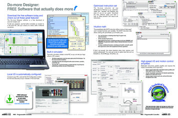
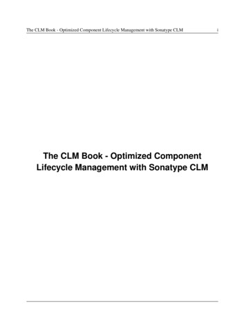
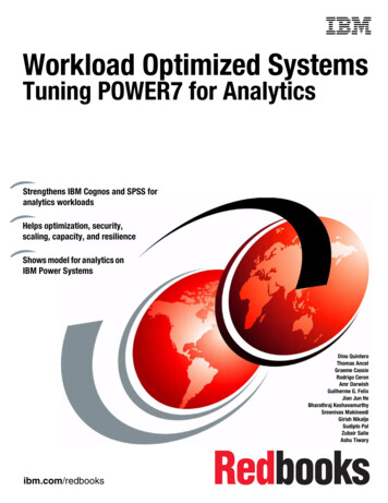
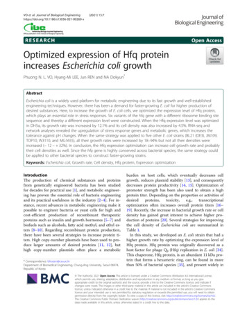
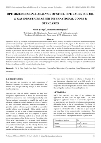
IJRET: International Journal of Research in Engineering and TechnologyeISSN: 2319-1163 pISSN: 2321-7308Fig.1 Keyplan PR-06 AFig.3 3-D VIEWPiperack is designed as moment resisting frames in thetransverse direction. The lateral forces in the transversedirection are transferred to base plate/ foundation bymoment resisting frame. In the longitudinal direction, thereis continuous level of beam struts on each side. Verticalbracing in the longitudinal direction is provided to carry thelongitudinal forces, transmitted through the beam struts, tothe base plate/ foundation level.4. DESIGN LOAD CALCULATIONFig.2 Section View Part-1Basic loads are applied in Staad Model, as applicable, on thestructure and its elements in form of 46 no.of Load Cases.Load Cases includes all the basic loads such as Dead loads,Live Loads, Wind, Seismic, Test loads, Operating loads, etc.Each load case is described in brief in this section. ASCE705 primary load cases are as follows Dead Load DL: Live Load LL Empty Weight of Equipment EE Operating Weight of Piping EO Test Weight of Equipment / Piping ET Temperature load TL( ) & TL(-) Thermal friction Load TF Thermal Anchor Load TA Ext Wind in x Direction ( WL X & WL-X) Seismic X EQXVolume: 05 Issue: 10 Oct-2016, Available @ http://ijret.esatjournals.org18
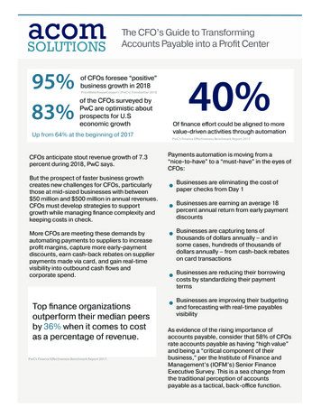
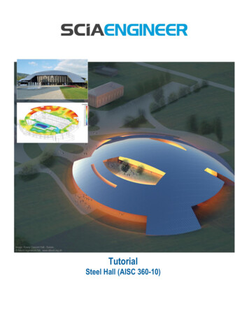
IJRET: International Journal of Research in Engineering and Technology Seismic X EQXOperating Blanket Load Vertical for checkingminimum load ConditionOperating Blanket Load frictional for checkingminimum load ConditionOperating Blanket Load Anchor for checkingminimum load ConditioneISSN: 2319-1163 pISSN: 2321-7308Superstructure and Substructure sections.Above Wind load and Seismic parameters has been appliedin the present thesis and piping stress load from a standardorganization in Kuwait has been used for loading the currentgeometry for lateral behavior of the structure.5. DESIGN PARAMETERSDesign parameters has been applied in staad model undertwo different sections namely, Strength Design Check &Serviceability Check. Code LRFD has been used. Strength Check1)Tensile Strength 41368 kN/m22)Yield Strength 275000 kN/m23)Allowable L/R in compression 2004)LY, LZ,UNB & UNT to column and beams5)KZ 1.2 to columns6)Net Section Factor 0.9 to all beams7)Net Section Factor 0.6 to all bracings8)Utility Ratio 0.85 till 9.0m9)Utility Ratio 0.9 above 9.0m Strength Check1)Deflection DJ1 & DJ2 to all beams2)DFF 300 to all beams3)Utility Ratio 0.85 till 9.0m4)Utility Ratio 0.9 above 9.0mFig.4 Wind Load DataFig.5 Seismic Load Data EQX6. STAAD RESULTSDifferent Results obtained from the Staad model has beenrepresented here in the form of images:6.1 Sway CheckModelFig.6 Seismic Load Data EQZVarious Primary load cases as mentioned above has beenconsidered which are used worldwide in oil and gas industryto study the behavior of the structure and to get the 5.00FrameHeight(upperTier )(mm)13.2AllowableDeflection H/200(mm)66Volume: 05 Issue: 10 Oct-2016, Available @ http://ijret.esatjournals.org19
IJRET: International Journal of Research in Engineering and TechnologyeISSN: 2319-1163 pISSN: 2321-73086.1 Storey Drift CheckTier LevelHeight (m )Displacement(mm)AllowabledisplacementH/150 (mm)108.007.68.050.67113.205.227.034.676.3 Vertical Deflection Check for Bridge6.4 Utility Ratio Check6.4.1 ColumnsVolume: 05 Issue: 10 Oct-2016, Available @ http://ijret.esatjournals.org20
IJRET: International Journal of Research in Engineering and TechnologyeISSN: 2319-1163 pISSN: 2321-73086.4.2 Stub Columns6.4.3 Transverse BracingVolume: 05 Issue: 10 Oct-2016, Available @ http://ijret.esatjournals.org21
IJRET: International Journal of Research in Engineering and TechnologyeISSN: 2319-1163 pISSN: 2321-73086.4.4 Longitudinal BracingVolume: 05 Issue: 10 Oct-2016, Available @ http://ijret.esatjournals.org22
IJRET: International Journal of Research in Engineering and TechnologyeISSN: 2319-1163 pISSN: 2321-73086.4.5 Plan Bracing6.4.6 Transverse BeamVolume: 05 Issue: 10 Oct-2016, Available @ http://ijret.esatjournals.org23
IJRET: International Journal of Research in Engineering and TechnologyeISSN: 2319-1163 pISSN: 2321-73086.4.7 Longitudinal BeamVolume: 05 Issue: 10 Oct-2016, Available @ http://ijret.esatjournals.org24
IJRET: International Journal of Research in Engineering and TechnologyeISSN: 2319-1163 pISSN: 2321-73086.4.8 Check for longitudinal tie beamAs per Industries longitudinal tie beams are to be checkedfor additional axial load of 15% of adjacent column load.6.4.9 Support Reaction Summary6.4.9.1 Base Plate – 16.4.9.2 Base Plate – 2Volume: 05 Issue: 10 Oct-2016, Available @ http://ijret.esatjournals.org25
IJRET: International Journal of Research in Engineering and TechnologyeISSN: 2319-1163 pISSN: 2321-73086.4.9.3 Base Plate – 3Volume: 05 Issue: 10 Oct-2016, Available @ http://ijret.es
(AISC 360-10) stability analysis shall consider the influence of second order effects (P-Δ and P-δ effects), flexural, shear and axial deformations, geometric imperfections, and member stiffness reduction due to residual stresses. The main reason for life loss is collapse of structures It is said that natural calamities itself never kills people; it is badly constructed structure that kill .