Transcription
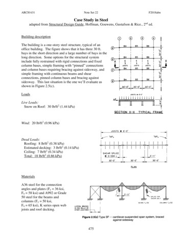
ARCH 631Note Set 22F2018abnCase Study in Steeladapted from Structural Design Guide, Hoffman, Gouwens, Gustafson & Rice., 2nd ed.Building descriptionThe building is a one-story steel structure, typical of anoffice building. The figure shows that it has three 30 ft.bays in the short direction and a large number of bays in thelong direction. Some options for the structural systeminclude fully restrained with rigid connections and fixedcolumn bases, simple framing with “pinned” connectionsand column bases requiring bracing against sidesway, andsimple framing with continuous beams and shearconnections, pinned column bases and bracing againstsidesway. This last situation is the one we’ll evaluate asshown in Figure 2.5(c).LoadsLive Loads:Snow on Roof: 30 lb/ft2 (1.44 kPa)Wind: 20 lb/ft2 (0.96 kPa)Dead Loads:Roofing: 8 lb/ft2 (0.38 kPa)Estimated decking: 3 lb/ft2 (0.14 kPa)Ceiling: 7 lb/ft2 (0.34 kPa)Total: 18 lb/ft2 (0.86 kPa)MaterialsA36 steel for the connectionangles and plates (Fy 36 ksi,Fu 58 ksi) and A992 or Grade50 steel for the beams andcolumns (Fy 50 ksi,Fu 65 ksi), K series open webjoists and roof decking.5050475
ARCH 631Note Set 22F2018abnDecking:Decking selection is typically allowable stress design. Tables will give allowable total uniformload (taking self weight into account) based on stresses and deflection criteria for typical spansand how many spans are supported. The table (and description) for a Vulcraft 1.0 E roof deckis provided.The total load with snow and roofing 30 psf 8 psf 38 psf.The types have the following weights (from the catalog): E26, E24, E22, E20 of 1.06 psf, 1.38 psf,1.67 psf, and 2.01 psf, respectively.Open Web Joists:Open web joist selection is either based on allowable stress design or LRFD resistance forflexure with elastic live load deflection). The total factored distributed load for joists at 6 ft oncenter will be:wtotal (1.2 18lb/ft2 1.6 30 lb/ft2)(6 ft) 1.2(8 lb/ft estimated) 427.2 lb/ft (with 1.2D 1.6(L, or Lr, or S, or R) by catalogue)wlive 30 lb/ft2(6 ft) 180 lb/ftwlive-adjusted 180 lb/ft L / 360 120 lb/ft L / 240 476
ARCH 631Note Set 22F2018abnThe top values are total factored load capacity, while the red values are unfactored live load capacityfor a deflection limit of L/360. We have roof beams-plaster ceiling with a live load deflection limit ofL/240. To use the chart, we either multiply the red values by 1.5 or divide our live load by 1.5.Deflection will not limit the selection, and the most lightweight choice is the 22K4 which weighsapproximately 8 lb/ft. Special provisions for bridging are required for the shaded area lengths andsections.Continuous Beams:LRFD design is required for the remaining structural steel for the combinations of load involving Dead,Snow and Wind. The bracing must be designed to resist the lateral wind load.The load values are:for D: wD 18 lb/ft2 30 ft (8 lb/ft 30 ft)/ 6 ft 580 lb/ftfor S: wS 30 lb/ft2 30 ft 900 lb/ftfor W: wW 20 lb/ft2 30 ft 600 lb/ft (up or down)and laterally V 600 lb/ft(15ft/2) 4500 lbThese DO NOT consider self weight of the beam.477
ARCH 631Note Set 22F2018abnThe applicable combinations for the tributary width of 30 ft. are:1.4Dwu 1.4(580 lb/ft) 812 lb/ft1.2D 1.6L 0.5(Lr or S or R)wu 1.2(580 lb/ft) 0.5(900 lb/ft) 1146 lb/ft1.2D 1.6(Lr or S or R) (L or 0.5W)wu 1.2(580 lb/ft) 1.6(900 lb/ft) 0.5(600 lb/ft) 2436 lb/ft1.2D 1.0W L 0.5(Lr or S or R)wu 1.2(580 lb/ft) 1.0(600 lb/ft) 0.5(900 lb/ft) 1746 lb/ft1.2D 1.0E L 0.25Swu 1.2(580 lb/ft) 0.25(900 lb/ft) 921 lb/ft0.9D 1.0Wwu 0.9(580 lb/ft) 1.0(-600 lb/ft) [uplift] -78 lb/ft (up)L, R, Lr , & E & don’t exist for our case.For the largest load case, the shear & bending moment diagrams are:Total load on every span:478
ARCH 631Note Set 22F2018abnLive load on end spans with dead load on every span:Live load on two adjacent spans with dead load on every span:For the beams, we know that the maximum unbraced length is 6 ft. For the middle 6 feet of the endspan, the moment is nearly uniform, so Cb 1 is acceptable (Cb 1.08 for constant moment). For theinterior span, Cb is nearly 1 as well.479
ARCH 631Note Set 22F2018abnChoosing a W18x35 (Mu 229 k-ft) for the end beams, and a W14x34 (Mu 200.2 k-ft) for the interiorbeam, the self weight can be included in the total weight. The diagrams change to:Check beam shear: Vu vVn 1.0(0.6Fyw Aw )Exterior Vu 34.67 k 1.0(0.6)(50 ksi)(17.1 in.)(0.3 in.) 153.9 kOKW18x35: d 17.7 in., tw 0.3 in., Ix 510 in.4Interior Vu 45.06 k 1.0(0.6)(50 ksi)(14.0 in.)(0.285 in.) 119.7 kOKW14x34: d 14.0 in., tw 0.285 in., Ix 340 in.4Check deflection (NO LOAD FACTORS) for total and live load(gravity and snow).Exterior Beams and Interior Beam: worst deflection is from no liveload on the center span:Maximum total 1.97 in. in the end spans and 1.31 in. at midspanIs total L/240 360 in./240 1.5 in.? NO GOODWe need an I about (1.97 in./1.5 in.)(510 in4) 670 in.4 for the ends,with the mid section adequate.Maximum live 1.60 in. in the end spans and 1.74 in. at midspanIs live L/360 360 in./360 1.0 in.? NO GOODWe need an I about (1.6 in./1.0in.)(510 in.4) 816 in.4 for the ends,and similarly about 592 in4 for the mid section.Live load governs.480
ARCH 631Note Set 22F2018abnThe W21x44 is the most economical out of the sections for the ends, shown with bold type in thegroup, with Ix 843 in.4The W18x40 is the most economical out of the sections for the ends, shown with bold type in thegroup, with Ix 612 in.4Now, live 0.964 in., which is less than allowable.Columns:The load in the interior columns: Pu 88.5 k (sum of the shears).This column will see minimal eccentricity from the difference inshear and half the column depth as the moment arm.The load in the exterior columns: Pu 34.8 k. These columns willsee some eccentricity from the beam shear connections. We candetermine this by using half the column depth as the eccentricitydistance.The effective length of the columns is 15 ft (no intermediatebracing). Table 4-1 shows design strength in kips for W8 shapes(the smallest). The lightest section at 15 feet has a capacity of230 k; much greater than what we need even with eccentricity.The exterior column connection moment (unmagnified) when theW8x31 depth 8.0in1 ft(34.8k )( 8.0in )() 11.6 k-ft.2 12inThe magnification on the moment in a bracedframe is found from (with α 1.0 for LRFD)B1 Cm0.6 0.62 1.01 ( Pu P1e ) 1 (1)(34.8k / 971k )where Cm 0.6 when the moment at one support is 0So use 1.0(no increase in the moment): Mux (1.0)Muwhere P1e 2 EA( kL )2r 2 (29, 000ksi )(9.13in 2 ) 15 ft (12 in ft ) 3.47in 2 971kwhere kL/r is for the axis aboutwhich bending occurs (rx)The capacity of a W8x31 with an unbraced length of 15 ft (from another beam chart) 95.3 k-ft.ForPr 0.2 :Pc M uxM uyPu 2 c Pn b M nx b M ny 1.0 481
ARCH 631Note Set 2234.8k 0.15 0.2 :230kF2018abn 11.6k ft 34.8k 0.197 1.02( 230k ) 95.3k ft so OK for eccentric loading of the beam-column (but we knew that).Beam Shear Splice Connection:For this all-bolted single-plate shear splice, Ru 34.8 kW21x44: d 20.7 in., tw 0.350 in.sW18x40: d 17.9 in., tw 0.315 in.The plate material is A36 with Fy 36 ksi and Fu 58 ksi. We need to checkthat we can fit a plate within the fillets and provide enough distance from thelast holes to the edge.482
ARCH 631Note Set 22F2018abnFor the W18x40, T 15.5 in., which limits the plate height.For ¾ in. diameter A325-N bolts and standard holes without a concern fordeformation of the holes, the capacity per bolt is:shear:Group A, Thread condition N, single shear: rn 17.9 k/bolt34.8k n(17.9k / bolt )so n 1.94. Use 2 bolts (1@3 in. 2@1.25 5.5 in. 15.5 in.)bearing for 2 rows of bolts:depends on thickness of thinnest web (t 0.315 in.)and the connected materialBased on Hole Spacing: rn 78.3 k/bolt/in for A36, and 87.8 k/bolt/in for A992The full bearing strength requires 115 16 in. for the edge distance, and with 2 in., thebearing capacity is identical to that based on hole spacing. (There is no edge withthe flanges.)34.8k 2bolts (87.8k / bolt / in)(0.315in) 55.3 k OKIf the spacing between the holes across the splice is 4 in., the eccentricity, ex,is 2 inches. We need tofind C, which represents the number of bolts that are effective in resisting the eccentric shear force.rn is the nominal shear per bolt:Cmin is the 2 bolts we determined based on shear in the bolts.C off the table for 3 in. spacing is 1.18 (not enough) and for 6 in.spacing is 1.63 (again not enough). If we increase the number ofbolts in one vertical row to 3, the available strength of the boltgroup ( Rn C x rn) at 3 inches (we have room) will be 2.23).OK.(The available strength with rn found in Table 7-1 is 2.23x17.9k/bolt 39.9 k)With 3 inches between 3 bolts and an edge spacing of 2 inches,the plate will be (3x3 in. 2x2) or 13 in. tall. And the thicknesscan be determined from first finding the required net area byrupture: (0.6Fu)Anv Vuwhere 0.75Anv 34.8k/(0.75)(0.6 58ksi) 1.33 in2and then dividing by the length, less the bolt holes (1/8” larger than the bolts)t 1.33 in2/[13 in – 3bolt(3/4 1/8)in] 0.13 in: use 1/4” plate483
ARCH 631Note Set 22F2018abnCheck flexure of the plate:design moment:R e 34.8k 4in 69.9 k-inMu u 22yielding capacity: M n Fy S x 0.9(13 in. tall section, 1/4 in. thick) 0.25in(13in)2 0.9(36ksi) 6 228.1 k-in 69.6 k-in OKrupture M n Fu Snet 0.75IS net netcwhich can be looked up or calculated6(0.25in )(13in )3 3(0.25 )( 34 )in 2(0.25in )( 34 18 )(3in )2 41.8 in4121241.8in4 6.43in30.75(58ksi)(6.43in3 ) 279.7 k-in 69.6 k-in OK6.5inI net Snetin1 in 38Check shear yielding of the plate: Ru Rn 1.00Rn 0.6 Fy Ag(1.00)[0.6(36 ksi)(13 in.)(0.25 in.)] 70.2 k 34.8 k OKWe can check shear rupture of the plate: Ru Rn 0.75Rn 0.6 Fu Anv :for ¾” diameter bolts, the effective hole width is (0.75 1/8) 0.875 in.:(0.75)[0.6(58 ksi)(13 in. – 3 x 0.875 in.)(0.25 in.)] 67.7 k 34.8 k OK484
ARCH 631Note Set 22Check block shear rupture of the plate: Ru RnF2018abn 0.75Rn 0.6Fu Anv U bs Fu Ant 0.6Fy Agv U bs Fu Antwith Ubs 0.5 when the tensile stress is non-uniform. (The tensile stress switches directionacross the splice.) (and assuming 2 in. of width to the center of the bolt hole)Rn 0.6(58ksi)(0.25in)[2in 3in 3in 2.5holes (0.875)] 0.5(58ksi)(0.25in)(2in 0.875in 2) 61.9 k 0.6(36ksi )(0.25in)(2in 3in 3in) 0.5(58ksi )(0.25in)(2in 0.875in ) 54.5 k234.8 k 0.75(54.5 k) 40.9 k OKColumn Base Plate:Column base plates are designed for bearing on the concrete (concrete capacity) and plastic hingedevelopment from flexure because the column “punches” down the plate and it could bend upward nearthe edges of the column (shown as 0.8bf and 0.95d). The plate dimensions are B and N. The concretehas a compressive strength, f’c 3 ksi.For W8 x 31: d 8.0 in., bf 8.0 in., and if we provide width toput in bolt holes, we could use a 12 in. by12 in. plate (allowingabout 2 inches each side). We will look at the interior columnload of 89 k.minimum thickness: tmin l2 Pu0.9 Fy BNwhere l is the larger of m, n and n m (N – 0.95d)/2 (12 in. – 0.95 x 8.0 in.)/2 2.2 in.n (B – 0.8bf)/2 (12 in. – 0.8 x 8.0 in.)/2 2.8 in.n db f4 8.0in 8.0in 2.0 in.4 is derived from a term X which takes the bounding area of the column, the perimeter, the axial force,and the concrete compressive strength into account:4db f4db fPPu4 8.0in 8.0in89kX u 222(d b f ) c Pp (d b f ) c (0.85 f c ) BN (8.0in 8.0in) 0.65(0.85 3ksi)12in 12in 0.373 2 X 1(1 1 X ) 2 0.373 0.682 so n (0.682)(2.0 in.) 1.36 in.(1 1 0.373)485
ARCH 631Note Set 22F2018abntherefor: l 2.8 in.:tp l2 Pu2 79k 0.515 in. (2.8in)0.9 Fy BN0.9(36ksi)(12in)(12in)Use a 5/8 in. thick plate.The anchor bolts must also be able to resist lateral shear. There also is friction between the steel andconcrete to help. The International Building Code provided specifications for minimum edge distancesand anchorage.Continuous Beam over Interior Column:The design for this connection will involve a bearing plate at the top ofthe column, with a minimum number of bolts through the beam flanges tothe plate. Because there will be high local compression, stiffener platesfor the web will need to be added (refer to a plate girder design). Flexurewith a reduced cross section area of the flanges should be checked.486
The table (and description) for a Vulcraft 1.0 E roof deck is provided. The total load with snow and roofing 30 psf 8 psf 38 psf. The types have the following weights (from the catalog): E26, E24, E22, E20 of 1.06 psf, 1.38 psf, 1.67 psf, and 2.01 psf, respectively. Open Web Joists: Open web joist selection is either based on allowable stress design or LRFD resistance for flexure with .