Transcription
"MONORAIL" --- MONORAIL BEAM ANALYSISProgram Description:"MONORAIL" is a spreadsheet program written in MS-Excel for the purpose of analysis of either S-shape orW-shape underhung monorail beams analyzed as simple-spans with or without overhangs (cantilevers).Specifically, the x-axis and y-axis bending moments as well as any torsion effects are calculated. The actual andallowable stresses are determined, and the effect of lower flange bending is also addressed by two differentapproaches.This program is a workbook consisting of three (3) worksheets, described as follows:Worksheet NameDescriptionDocS-shaped Monorail BeamW-shaped Monorail BeamThis documentation sheetMonorail beam analysis for S-shaped beamsMonorail beam analysis for W-shaped beamsProgram Assumptions and Limitations:1. The following references were used in the development of this program:a. Fluor Enterprises, Inc. - Guideline 000.215.1257 - "Hoisting Facilities" (August 22, 2005)b. Dupont Engineering Design Standard: DB1X - "Design and Installation of Monorail Beams" (May 2000)c. American National Standards Institute (ANSI): MH27.1 - "Underhung Cranes and Monorail Syatems"d. American Institute of Steel Construction (AISC) 9th Edition Allowable Stress Design (ASD) Manual (1989)e. "Allowable Bending Stresses for Overhanging Monorails" - by N. Stephen Tanner AISC Engineering Journal (3rd Quarter, 1985)f. Crane Manufacturers Association of America, Inc. (CMAA) - Publication No. 74 "Specifications for Top Running & Under Running Single Girder Electric Traveling CranesUtilizing Under Running Trolley Hoist" (2004)g. "Design of Monorail Systems" - by Thomas H. Orihuela Jr., PE (www.pdhengineer.com)h. British Steel Code B.S. 449, pages 42-44 (1959)i. USS Steel Design Manual - Chapter 7 "Torsion" - by R. L. Brockenbrough and B.G. Johnston (1981)j. AISC Steel Design Guide Series No. 9 - "Torsional Analysis of Structural Steel Members" by Paul A. Seaburg, PhD, PE and Charlie J. Carter, PE (1997)k. "Technical Note: Torsion Analysis of Steel Sections" - by William E. Moore II and Keith M. Mueller AISC Engineering Journal (4th Quarter, 2002)2. The unbraced length for the overhang (cantilever) portion, 'Lbo', of an underhung monorail beam is often debated.The following are some recommendations from the references cited above:a. Fluor Guideline 000.215.1257: Lbo Lo L/2b. Dupont Standard DB1X: Lbo 3*Loc. ANSI Standard MH27.1: Lbo 2*Lod. British Steel Code B.S. 449: Lbo 2*Lo (for top flange of monorail beam restrained at support)British Steel Code B.S. 449: Lbo 3*Lo (for top flange of monorail beam unrestrained at support)e. AISC Eng. Journal Article by Tanner: Lbo Lo L (used with a computed value of 'Cbo' from article)3. This program also determines the calculated value of the bending coefficient, 'Cbo', for the overhang (cantilever)portion of the monorail beam from reference "e" in note #1 above. This is located off of the main calculation page.Note: if this computed value of 'Cbo' is used and input, then per this reference the total value of Lo L should beused for the unbraced length, 'Lbo', for the overhang portion of the monorail beam.4. This program ignores effects of axial compressive stress produced by any longitudinal (traction) force which isusually considered minimal for underhung, hand-operated monorail systems.5. This program contains “comment boxes” which contain a wide variety of information including explanations ofinput or output items, equations used, data tables, etc. (Note: presence of a “comment box” is denoted by a“red triangle” in the upper right-hand corner of a cell. Merely move the mouse pointer to the desired cell to viewthe contents of that particular "comment box".)
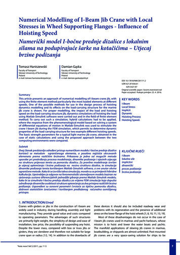
"MONORAIL.xls" ProgramVersion 1.6MONORAIL BEAM ANALYSISFor S-shaped Underhung Monorails Analyzed as Simple-Spans with / without OverhangPer AISC 9th Edition ASD Manual and CMAA Specification No. 74 (2004)Job Name:Subject:Job Number:Originator:Checker:Input:RL(min) -0.73Monorail Size:Select:Design Parameters:Beam Fy Beam Simple-Span, L Unbraced Length, Lb Bending Coef., Cb Overhang Length, Lo Unbraced Length, Lbo Bending Coef., Cbo Lifted Load, P Trolley Weight, Wt Hoist Weight, Wh Vert. Impact Factor, Vi Horz. Load Factor, HLF Total No. Wheels, Nw Wheel Spacing, S Distance on Flange, a RR(max) 9.13Lo 3L 17S12x50x 8.313S 00.100151040.75000.3750Results:Parameters and Coefficients:Pv 7.400 kipsPw 1.850 kips/wheelPh 0.600 kipsta 0.493 in.l 0.156Cxo -0.850Cx1 0.600Czo 0.165Cz1 1.948ksiS12x50ft.ft.Pv 7.4Nomenclatureft.ft.kipskipskips%%ft.A d tw bf tf k rt S12x50 Member Properties:14.60 in. 2d/Af 3.3212.000 in.Ix 303.000.687 in.Sx 50.605.480 in.Iy 15.600.659 in.Sy 5.691.438 in.J 2.7701.250 in.Cw 502.0in. 4in. 3in. 4in. 3in. 4in. 6in.Support Reactions: (with overhang)RR(max) 9.13 Pv*(L (Lo-S/2))/L w/1000/(2*L)*(L Lo) 2RL(min) -0.73 -Pv*(Lo-S/2)/L w/1000/(2*L)*(L 2-Lo 2)Pv P*(1 Vi/100) Wt Wh (vertical load)Pw Pv/Nw (load per trolley wheel)Ph HLF*P (horizontal load)ta tf-bf/24 a/6 (for S-shape)l 2*a/(bf-tw)Cxo -1.096 1.095*l 0.192*e (-6.0*l)Cx1 3.965-4.835*l-3.965*e (-2.675*l)Czo -0.981-1.479*l 1.120*e (1.322*l)Cz1 1.810-1.150*l 1.060*e (-7.70*l)Bending Moments for Simple-Span:x 8.313 ft.x 1/2*(L-S/2) (location of max. moments from left end of simple-span)Mx 31.88 ft-kipsMx (Pv/2)/(2*L)*(L-S/2) 2 w/1000*x/2*(L-x)My 2.44ft-kipsMy (Ph/2)/(2*L)*(L-S/2) 2Lateral Flange Bending Moment from Torsion for Simple-Span:(per USS Steel Design Manual, 1981)e 6.000 in.e d/2 (assume horiz. load taken at bot. flange)at 21.662at SQRT(E*Cw/(J*G)) , E 29000 ksi and G 11200 ksiMt 0.29ft-kipsMt Ph*e*at/(2*(d-tf))*TANH(L*12/(2*at))/12X-axis Stresses for Simple-Span:fbx 7.56ksiLb/rt 163.20Fbx 17.72 ksifbx Mx/SxLb/rt Lb*12/rtFbx 12000*Cb/(Lb*12*(d/Af)) 0.60*Fyfbx Fbx, O.K.(continued)2 of 77/22/2013 7:29 AM
"MONORAIL.xls" ProgramVersion 1.6Y-axis Stresses for Simple-Span:fby 5.14ksifwns 1.21ksifby(total) 6.35ksiFby 27.00 ksifby My/Syfwns Mt*12/(Sy/2) (warping normal stress)fby(total) fby fwnsFby 0.75*FyCombined Stress Ratio for Simple-Span:S.R. 0.662S.R. fbx/Fbx fby(total)/Fbyfby Fby, O.K.S.R. 1.0, O.K.Vertical Deflection for Simple-Span:Pv 6.500 kipsPv P Wh Wt (without vertical impact)D(max) 0.1412 in.D(max) Pv/2*(L-S)/2/(24*E*I)*(3*L 2-4*((L-S)/2) 2) 5*w/12000*L 4/(384*E*I)D(ratio) L/1445D(ratio) L*12/D(max)D(allow) 0.4533 in.D(allow) L*12/450Defl.(max) Defl.(allow), O.K.Bending Moments for Overhang:Mx 19.65 ft-kipsMy 1.58ft-kipsMx (Pv/2)*(Lo (Lo-S)) w/1000*Lo 2/2My (Ph/2)*(Lo (Lo-S))Lateral Flange Bending Moment from Torsion for Overhang:(per USS Steel Design Manual, 1981)e 6.000 in.e d/2 (assume horiz. load taken at bot. flange)at 21.662at SQRT(E*Cw/(J*G)) , E 29000 ksi and G 11200 ksiMt 0.57ft-kipsMt Ph*e*at/(d-tf)*TANH(Lo*12/at)/12X-axis Stresses for Overhang:fbx 4.66ksiLbo/rt 110.40Fbx 21.60 ksifbx Mx/SxLbo/rt Lbo*12/rtFbx 12000*Cbo/(Lbo*12*(d/Af)) 0.60*Fyfbx Fbx, O.K.Y-axis Stresses for Overhang:fby 3.32ksifwns 2.42ksifby(total) 5.74ksiFby 27.00 ksifby My/Syfwns Mt*12/(Sy/2) (warping normal stress)fby(total) fby fwnsFby 0.75*Fyfby Fby, O.K.Combined Stress Ratio for Overhang:S.R. 0.428S.R. fbx/Fbx fby(total)/FbyVertical Deflection for Overhang:Pv 6.500 kipsD(max) 0.0715 in.D(ratio) L/503D(allow) 0.0800 in.S.R. 1.0, O.K.(assuming full design load, Pv without impact, at end of overhang)Pv P Wh Wt (without vertical impact)D(max) Pv*Lo 2*(L Lo)/(3*E*I) w/12000*Lo*(4*Lo 2*L-L 3 3*Lo 3)/(24*E*I)D(ratio) Lo*12/D(max)D(allow) Lo*12/450Defl.(max) Defl.(allow), O.K.Bottom Flange Bending (simplified):be 7.908 in.Min. of: be 12*tf or S*12 (effective flange bending length)tf2 0.859 in.tf2 tf (bf/2-tw/2)/2*(1/6) (flange thk. at web based on 1:6 slope of flange)am 1.818 in.am (bf/2-tw/2)-(k-tf2) (where: k-tf2 radius of fillet)Mf 3.363 in.-kipsMf Pw*amSf 0.572 in. 3Sf be*tf 2/6fb 5.88ksifb Mf/SfFb 27.00 ksiFb 0.75*Fyfb Fb, O.K.(continued)3 of 77/22/2013 7:29 AM
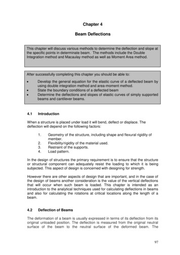
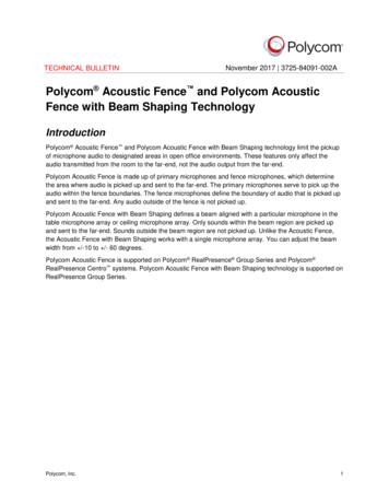
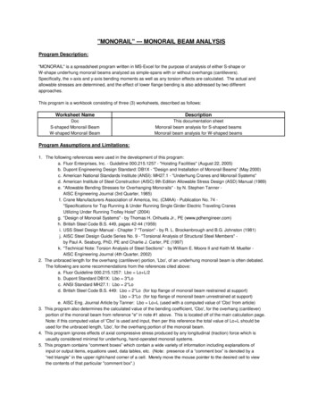
"MONORAIL.xls" ProgramVersion 1.6Bottom Flange Bending per CMAA Specification No. 74 (2004):Local Flange Bending Stress @ Point 0:sxo sxo Cxo*Pw/ta 2-6.46ksiszo szo Czo*Pw/ta 21.25ksi(Note: torsion is neglected)(Sign convention: tension, - compression)S-shapeLocal Flange Bending Stress @ Point 1:sx1 sx1 Cx1*Pw/ta 24.56ksisz1 sz1 Cz1*Pw/ta 214.82 ksiTrolleyWheelLocal Flange Bending Stress @ Point 2:sx2 sx2 -sxo6.46ksisz2 sz2 -szo-1.25ksiPwPwResultant Biaxial Stress @ Point 0:sz 13.65 ksisx -4.85ksitxz 0.00ksisto 16.61 ksisz fbx fby 0.75*szosx 0.75*sxotxz 0 (assumed negligible)sto SQRT(sx 2 sz 2-sx*sz 3*txz 2) Fb 0.66*Fy 23.76 ksi, O.K.Resultant Biaxial Stress @ Point 1:sz 23.82 ksisx 3.42ksitxz 0.00ksist1 22.30 ksisz fbx fby 0.75*sz1sx 0.75*sx1txz 0 (assumed negligible)st1 SQRT(sx 2 sz 2-sx*sz 3*txz 2) Fb 0.66*Fy 23.76 ksi, O.K.Resultant Biaxial Stress @ Point 2:sz 11.76 ksisx 4.85ksitxz 0.00ksist2 10.24 ksisz fbx fby 0.75*sz2sx 0.75*sx2txz 0 (assumed negligible)st2 SQRT(sx 2 sz 2-sx*sz 3*txz 2) Fb 0.66*Fy 23.76 ksi, O.K.YtwXPwPwZtfPoint 2Point 0Point 1tabf/4tw/2bf4 of 77/22/2013 7:29 AM
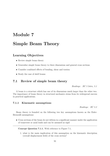
"MONORAIL.xls" ProgramVersion 1.6MONORAIL BEAM ANALYSISFor W-shaped Underhung Monorails Analyzed as Simple-Spans with / without OverhangPer AISC 9th Edition ASD Manual and CMAA Specification No. 74 (2004)Job Name:Subject:Job Number:Originator:Checker:Input:RL(min) -0.73Monorail Size:Select:Design Parameters:Beam Fy Beam Simple-Span, L Unbraced Length, Lb Bending Coef., Cb Overhang Length, Lo Unbraced Length, Lbo Bending Coef., Cbo Lifted Load, P Trolley Weight, Wt Hoist Weight, Wh Vert. Impact Factor, Vi Horz. Load Factor, HLF Total No. Wheels, Nw Wheel Spacing, S Distance on Flange, a RR(max) 9.13Lo 3L 17W12x50x 8.313S 00.100151040.75000.3750Results:Parameters and Coefficients:Pv 7.400 kipsPw 1.850 kips/wheelPh 0.600 kipsta 0.640 in.l 0.097Cxo -1.903Cx1 0.535Czo 0.192Cz1 2.319ksiW12x50ft.ft.Pv 7.4Nomenclatureft.ft.kipskipskips%%ft.A d tw bf tf k rt W12x50 Member Properties:14.60 in. 2d/Af 2.3612.200 in.Ix 391.000.370 in.Sx 64.208.080 in.Iy 56.300.640 in.Sy 13.901.140 in.J 1.7102.170 in.Cw 1880.0in. 4in. 3in. 4in. 3in. 4in. 6in.Support Reactions: (with overhang)RR(max) 9.13 Pv*(L (Lo-S/2))/L w/1000/(2*L)*(L Lo) 2RL(min) -0.73 -Pv*(Lo-S/2)/L w/1000/(2*L)*(L 2-Lo 2)Pv P*(1 Vi/100) Wt Wh (vertical load)Pw Pv/Nw (load per trolley wheel)Ph HLF*P (horizontal load)ta tf (for W-shape)l 2*a/(bf-tw)Cxo -2.110 1.977*l 0.0076*e (6.53*l)Cx1 10.108-7.408*l-10.108*e (-1.364*l)Czo 0.050-0.580*l 0.148*e (3.015*l)Cz1 2.230-1.490*l 1.390*e (-18.33*l)Bending Moments for Simple-Span:x 8.313 ft.x 1/2*(L-S/2) (location of max. moments from left end of simple-span)Mx 31.88 ft-kipsMx (Pv/2)/(2*L)*(L-S/2) 2 w/1000*x/2*(L-x)My 2.44ft-kipsMy (Ph/2)/(2*L)*(L-S/2) 2Lateral Flange Bending Moment from Torsion for Simple-Span:(per USS Steel Design Manual, 1981)e 6.100 in.e d/2 (assume horiz. load taken at bot. flange)at 53.354at SQRT(E*Cw/(J*G)) , E 29000 ksi and G 11200 ksiMt 0.67ft-kipsMt Ph*e*at/(2*(d-tf))*TANH(L*12/(2*at))/12X-axis Stresses for Simple-Span:fbx 5.96ksiLb/rt 94.01Fbx 21.60 ksifbx Mx/SxLb/rt Lb*12/rtFbx 12000*Cb/(Lb*12*(d/Af)) 0.60*Fyfbx Fbx, O.K.(continued)5 of 77/22/2013 7:29 AM
"MONORAIL.xls" ProgramVersion 1.6Y-axis Stresses for Simple-Span:fby 2.11ksifwns 1.16ksifby(total) 3.27ksiFby 27.00 ksifby My/Syfwns Mt*12/(Sy/2) (warping normal stress)fby(total) fby fwnsFby 0.75*FyCombined Stress Ratio for Simple-Span:S.R. 0.397S.R. fbx/Fbx fby(total)/Fbyfby Fby, O.K.S.R. 1.0, O.K.Vertical Deflection for Simple-Span:Pv 6.500 kipsPv P Wh Wt (without vertical impact)D(max) 0.1094 in.D(max) Pv/2*(L-S)/2/(24*E*I)*(3*L 2-4*((L-S)/2) 2) 5*w/12000*L 4/(384*E*I)D(ratio) L/1865D(ratio) L*12/D(max)D(allow) 0.4533 in.D(allow) L*12/450Defl.(max) Defl.(allow), O.K.Bending Moments for Overhang:Mx 19.65 ft-kipsMy 1.58ft-kipsMx (Pv/2)*(Lo (Lo-S)) w/1000*Lo 2/2My (Ph/2)*(Lo (Lo-S))Lateral Flange Bending Moment from Torsion for Overhang:(per USS Steel Design Manual, 1981)e 6.100 in.e d/2 (assume horiz. load taken at bot. flange)at 53.354at SQRT(E*Cw/(J*G)) , E 29000 ksi and G 11200 ksiMt 1.41ft-kipsMt Ph*e*at/(d-tf)*TANH(Lo*12/at)/12X-axis Stresses for Overhang:fbx 3.67ksiLbo/rt 63.59Fbx 21.60 ksifbx Mx/SxLbo/rt Lbo*12/rtFbx 12000*Cbo/(Lbo*12*(d/Af)) 0.60*Fyfbx Fbx, O.K.Y-axis Stresses for Overhang:fby 1.36ksifwns 2.43ksifby(total) 3.79ksiFby 27.00 ksifby My/Syfwns Mt*12/(Sy/2) (warping normal stress)fby(total) fby fwnsFby 0.75*Fyfby Fby, O.K.Combined Stress Ratio for Overhang:S.R. 0.310S.R. fbx/Fbx fby(total)/FbyVertical Deflection for Overhang:Pv 6.500 kipsD(max) 0.0554 in.D(ratio) L/650D(allow) 0.0800 in.S.R. 1.0, O.K.(assuming full design load, Pv without impact, at end of overhang)Pv P Wh Wt (without vertical impact)D(max) Pv*Lo 2*(L Lo)/(3*E*I) w/12000*Lo*(4*Lo 2*L-L 3 3*Lo 3)/(24*E*I)D(ratio) Lo*12/D(max)D(allow) Lo*12/450Defl.(max) Defl.(allow), O.K.Bottom Flange Bending (simplified):be 7.680 in.Min. of: be 12*tf or S*12 (effective flange bending length)am 3.355 in.am (bf/2-tw/2)-(k-tf) (where: k-tf radius of fillet)Mf 6.207 in.-kipsMf Pw*amSf 0.524 in. 3Sf be*tf 2/6fb 11.84 ksifb Mf/SfFb 27.00 ksiFb 0.75*Fyfb Fb, O.K.(continued)6 of 77/22/2013 7:29 AM
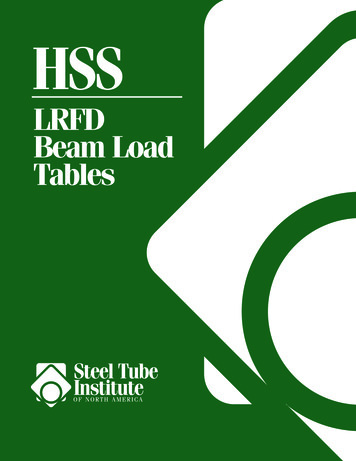
"MONORAIL.xls" ProgramVersion 1.6Bottom Flange Bending per CMAA Specification No. 74 (2004):Local Flange Bending Stress @ Point 0:sxo sxo Cxo*Pw/ta 2-8.60ksiszo szo Czo*Pw/ta 20.87ksi(Note: torsion is neglected)(Sign conventio
Bottom Flange Bending per CMAA Specification No. 74 (2004): (Note: torsion is neglected) Local Flange Bending Stress @ Point 0: (Sign convention: tension, - compression) sxo -6.46 ksi sxo Cxo*Pw/ta 2 szo 1.25 ksi szo Czo*Pw/ta 2 Local Flange Bending Stress @ Point 1: sx1 4.56 ksi sx1 Cx1*Pw/ta 2 sz1 14.82 ksi sz1 Cz1*Pw/ta 2File Size: 240KBPage Count: 7