Transcription
Cadence Virtuoso Tutorialversion 6.1University of Southern CaliforniaLast Update: Oct, 2015EE209 – Fall 2015
Table of ContentsSystem Setup . 31. Basic setup . 32. Cadence setup. 3Basic Design Flow . 51. Overall design flow . 52. Create Library . 63. Schematic . 8A. Create a cell view . 8B. Draw a schematic . 94. Run Spectre simulation (Transient analysis) . 16A. Launch ADE (Analog Design Environment) L . 16B. Basic setup . 17C. Model Libraries . 17D. Stimuli . 18E. Choose a type of analysis - transient . 20F. Select signals to plot . 21G. Run simulation . 21H. Measurement . 225. Run Spectre simulation (DC analysis) . 25A. Voltage Source . 25B. Replace Input Pin . 26C. Choosing Analyses . 26D. Run Simulation . 276. Layout. 29A. Create a layout . 29B. Add an instance - nmos . 30C. Add more instances – pmos, ptap, ntap, and m1 ploy . 31D. Draw metal1 . 32E. Run DRC . 33F. Add pins . 35G. Extract . 37H. Run LVS . 38I. Run Spectre simulation. 39
System SetupBasic setupCadence can only run on the unix machines at USC (e.g., viterbi-scf1). You will need to remote login (XTerm) to these machines to run the tools.If you’re using Windows, download X-Win32 2012 (for remote login) and Filezilla (for file transfer)from http://software.usc.edu (usc account login required)If you’re using MAC or Ubuntu, use terminal command “ssh -X” for remote login and “scp” or“sftp” for file transfer. If you’re not familiar, please read this tutorial for more ssh-and-scp-howto-tips-tricksIf you have any license issues when you run X-Win32, you can either try to connect to USCWireless Plus (how-to link: http://www.usc.edu/its/wireless/plus/) or use USC VPN (how-tolink: n32 Connection SetupTo remote login using X-Win32, select Manual and choose ssh:Connection Name: (anything you like)Host: viterbi-scf1.usc.eduLogin: (your my.usc.edu account name)Command: /usr/bin/xtermPassword: (your my.usc.edu account password)
Save your connection. Launch it:If you see the xterm window like below, congratulations your X-Win32 is all setup.
b)Filezilla Connection SetupOpen Filezilla, use viterbi-scf1.usc.edu as host and 22 as Port. The username and passwordare the same as your X-Win32 connection.Navigate and choose files from the left window to upload and files from the right window todownload.
Cadence setupBefore you start, familiarize yourself with the following linux commands:ls// List filespwdcdmvcp// Show your current directory// Navigate to some directory// Move// CopyYou can find 'cshrc linux',tsmc.spice and 'vlsi tools.csh'from http://bits.usc.edu/ee209/site. Note that the file entitledrm// Remove'cshrc linux' should be renamed to'.cshrc' after uploading it in yourmkdir// Create a directoryGoogle them for more information about their usage if needed. home directory.Download .cshrc, tsmc.spice and vlsi tools.csh from http://bits.usc.edu/ee209/ under Lab Tutorial.Use Filezilla (or scp) to upload these files to your home folder on viterbi-scf1. Make sure theyare named .cshrc or vlsi tools.csh exactly.Type command “ls –a” to list all files under your home directory:ls -aIf you need to editthe linux files, don'tedit them byWindow basededitor (e.g., Word,Text). You have touse unix editors,such as gedit, vi,emacs.If you need to rename those files to .cshrc or vlsi tools.csh, use command “mv”, for example,to rename cshrc to .cshrc, you can say:mv cshrc .cshrcConvert the encoding of those two files by dos2unix command:dos2unix .cshrcdos2unix vlsi tools.cshCreate a folder named cds:mkdir cdsCopy useful files to your cds directory:cp ee577/design pdk/tsmc25/files/* ./cds/cp ee577/design pdk/tsmc25/files/.cds* ./cds/Check you have the following files in the cds folder:ls -a ./cds/.cdsinit// cadence initialized file
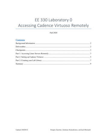
.cdsplotinitcds.lib// cadence printing setup file// cadence library setup fileschBindKeys.iltsmc25.spice// Binding key files for shortcut keys// TSMC 25 spice parametersleBindKeys.ilNow go to the cds folder:cd cdsUse gedit to open cds.lib:gedit cds.lib// Binding key files for shortcut keysThis step is no more necessaryAdd the following line to it; do not remove any existing content:INCLUDE CDK DIR/cdssetup/cds.lib Or you can you type 'cd ', whenevergoing back to home directoryGo back to your home directory:cd .Copy the cadence environment files to your cds working directory:cp ee577/design pdk/ncsu-cdk-1.6.0.beta/cdssetup/cdsinit ./cds/.cdsinitCopy the .simrc file to your cds directory:cp ee577/design pdk/ncsu-cdk-1.6.0.beta/cdssetup/simrc ./cds/.simrcThen you can source .cshrc file:source .cshrcIf nothing comes out, then you’re successful:
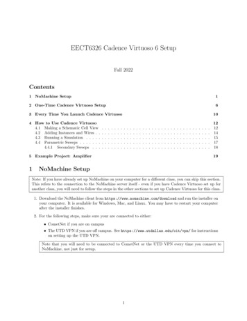
Please remember that you need to source .cshrc every time you login before runningvirtuoso. You don’t need to repeat other steps though.To run virtuoso, now go to cds directory: (always run virtuoso in the cds directory)cd cdsAnd open virtuoso: (by adding & you can use virtuoso and xterm and the same time)virtuoso &Make sure you can see those NCSU XX libraries and then you’re all set!
.cdsplotinit// cadence printing setup filecds.libschBindKeys.il// cadence library setup file// Binding key files for shortcut keystsmc25.spice// TSMC 25 spice parametersleBindKeys.il// Binding key files for shortcut keysA. Make sure you can run cadence tool by typing.%which /virtuosoB. Go to your home directory, open your .cshrc file and add the following lines at the end of thisfile:setenv CDK DIR /home/scf-06/ee577/design pdk/ncsu-cdk-1.6.0.betasetenv CDS Netlisting Mode AnalogC. Close the .cshrc file and source this file by typing the following command:% source .cshrcD. Open the library file cds.lib which is located in your cds directory. Just add the following lineto cds.lib. Do not remove existing contents in cds.lib:INCLUDE CDK DIR/cdssetup/cds.libE. Go to your home directory. Copy the cadence environment files to your cds working directoryby typing the following command while you are in your home directory:%cp ee577/design pdk/ncsu-cdk-1.6.0.beta/cdssetup/cdsinit ./cds/.cdsinitF. Stay at your home directory. Copy the .simrc file in your cds directory by typing the followingcommand while you are in your home directory:% cp ee577/design pdk/ncsu-cdk-1.6.0.beta/cdssetup/simrc ./cds/.simrcNote that the name of the file that you are accessing is “cdsinit” but you need to save itas “.cdsinit”. Also note that you may already have a “.cdsinit” file from the past in yourcds directory. In this case you still need to overwrite it by this new file.G. Always invoke "virtuoso" in your /cds directory because all setup files are in this directory.Type virtuoso & at the command prompt. The “&” is for background execution, it is usefulwhen we want to keep the command prompt in the same console.
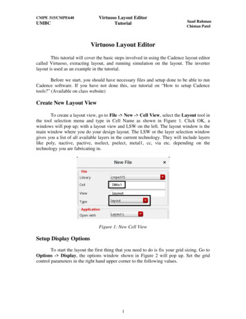
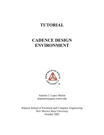
Basic Design Flow1. Overall design flowFollowing flow chart shows overall design flow.
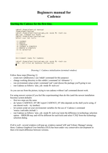
2. Create LibraryFor prompt to access for higher tiered license, click “always”.A. Tools Library ManagerB. File New Library
C. Give a name and attach it to a technology library
3. SchematicA. Create a cell viewselect the library just created, File- new
B. Draw a schematici.Add instances – pmosYou can modify Width of transistors. Don‟t modify length unless you have a special purpose.You should select a NCSU Analog Parts library.
ii.Add instances – nmos, vdd, and gnd
iii.Add wires:Create Wire
iv.Add pins:Create PinWe have for different types of direction. For schematics, we only use two types, input andoutput. InputOutput type is for supply changes, and it is necessary only for layout. We willdiscuss about this later.
Check and save to make sure there are no errors.Now, we completed a schematic design.C. Create a symbol (Optional)For hierarchical design, we may need to make symbols of designed circuits.Create CellView From Cellview
Remember that when you use more than one symbol in schematic, they all will have commonVdd and Gnd even if there are one Gnd and Vdd for each symbol (in the original design). Todesign with symbols in layout, you should make sure that all of the Vdd and Gnds areconnected.
4. Run Spectre simulation (Transient analysis)We will run spectre simulation. This section is for both schematics and layouts. I will show anexample for a schematic. You can do the same thing for a layout.A. Launch ADE (Analog Design Environment) LLaunch ADE L
B. Basic setupCheck if your simulator is spectre. You can modify project directory.C. Model LibrariesYou can download a library file at the DEN blackboard.Put the tech file under /home/scf-10/your-user-name/cds/techfiles/
Please only use the provided tsmc file because some tsmc files does not work correctly.D. StimuliDefine input signals include supply nets (for layout, vdd! and gnd! are under inputs and bothshould be enabled.)
Global sourcesInput (change)Remember to check Enabled button and then press OK or APPLY otherwise you will lose theconfigured numbers.
E. Choose a type of analysis - transientYou can choose „dc‟ if you want to do dc analysisA. Choose tranB. Give Stop time which meanshowlong youwant tosimulateC. Select moderate as accuracydefaultsD. DonotcheckNoiseE. Check EnabledTransient
F. Select signals to plotOutputs To Be Plotted Select On SchematicClick a signal (Pin) on a schematic/extracted. In Extracted try to use pins for signal that youneed in the simulation because it is hard to select a net in the extracted view.G. Run simulationSimulation Run
If you see a waveform like above picture, you followed every step properly.Good job!.H. MeasurementThe following steps describe the measurement of rise time. Using similar steps otherparameters of delay, fall time can be estimated.Invoke the calculatoror tools- calculator , select the Wave radio button:
In the functions window – choose“all”Select the rise time option
Select the signal from the waveformwindow whose rise time needs to bedetermined and click “OK”:Clicktheevaluatebuffer to display results as followsYou can also select a signal from calculator for example cos(Vin) as one of the plotted signals andyou can see the results whenever you run the simulation.Remember to save the simulation setup to use it later. You can do so by clicking on Session Save State in the ADE (Analog Design Environment) window. Next time you want to simulate thesame cell, you can reload your configuration by clicking on Session Load State.
5. Run Spectre simulation (DC analysis)The following inverter schematic is already createdA. Voltage SourceFor DC analysis , the input pin “in” must be altered. The following are the steps to alter thepin “in” : Create instance NCSU analog parts Voltage sources select VdcThe DC voltage must be set to1.5V as shown.
B. Replace Input PinThe Input pin “in” must be replaced with the above voltage source as shown belowCheck and Save (make sure youget no errors)C. Choosing AnalysesLaunch ADE L, repeat steps A to D in section 3 of „Basic Design Flow‟ except that there is no“in” input signal this time.Go to Analyses Choose dcChoose „Component Parameter‟,Select Component, then the voltage source in theschematic, then choose 0 as Start, 1.5 as Stop and0.01 as step .
Make sure that there are no other analyses selected apart from DCD. Run SimulationDo simulations netlist and run. On successful completion we get the following
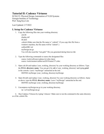
Now, go to the results Direct plot DC. Click on the output pin “out” on the schematic andESC key to get the following VTC
6. LayoutIt‟s time to draw layout. Schematics are for verifying your design very roughly. They don‟tconsider physical features like parasitic capacitances. After determining your design variables byschematics, you need to draw layouts.Design flow of layouts is very similar to one of schematics, but it has additional step which is LVScheck. It is for check if your layout is identical to the schematic or not. Hence, this step is veryimportant. If your logic doesn‟t pass this step, you may lose significant points for that.A. Create a layout
B. Add an instance - nmosYou can modify width of transistors.
C. Add more instances – pmos, ptap, ntap, and m1 ployYou can select alternate view of a layout. Try „Shift f‟ and „Ctrl f‟.
D. Draw metal1There are few ways for drawing metal, but I recommend you use „path‟. It‟s quiteconvenience than others.Create Shape PathFirst of all, you should select metal1 on LSW window. Default width for metal1 is 0.3, whichmeans 300nm (3 λ). You can draw metal layer simply by clicking
E. Run DRCThis step checks if your layout follows design rules.Verify DRC
We have five errors. It is because a gnd metal layer is too close to an nmos transistor.After modifying layout, run DRC again.There is no error!!
F. Add pinsWe had two pins on a schematic, which are „in‟ and „out‟. Pins are for assigning signals tophysical device, so we assign voltage level of gnd and vdd by using pins. Hence, we have 4 pinsfor the layout, which are „in‟, „out‟, „gnd!‟, and „vdd!‟.Create PinCheck „Display Terminal Name‟ if you want tosee pin name on the layout.Click „Display Terminal Option
G. ExtractA layout is just a picture. If you need to run simulation using the layout, you should convert it tothe other format. It is done by extracting. It‟s something like compiling a code.Select „Extract parastic cap‟ as a switch name,otherwise your extracted design won‟t have parasiticcapacitances.
H. Run LVSAs I mentioned before, this step is very important for your grading. More complicated design,more time will be required for debugging LVS.Verify LVSKeep in mind. You SHOULD compare your schematic with EXTRACTED.I hope all of you will see the following window.If there are errors, you can check the results by clicking „Output‟ button. „Error Display‟ alsomight be helpful.
I. Run Spectre simulationIt is same as schematics. Please follow the instructions for the schematics.Congratulations!!You followed all steps I prepared. Let‟s do the same thing for more complicated designs.
*Some useful informationUseful edu/wiki/NCSU EDA Wikihttp://www.cadence.com/community/forums/
To run virtuoso, now go to cds directory: (always run virtuoso in the cds directory) cd cds And open virtuoso: (by adding & you can use virtuoso and xterm and the same time)